| “This site contains affiliate links for which OEMDTC may be compensated” |
| 1.6L GTDI – ILLUMINATED MALFUNCTION INDICATOR LAMP (MIL) – DTC P0236 – BUILT ON OR BEFORE 30-SEP-2015 | |
| Publication Date: December 9, 2016 | |
FORD : : | 2015-2016 Escape |
ISSUE:
Some 2015-2016 Escape vehicles equipped with 1.6L Gasoline Turbocharged Direct Injection (GTDI) engines built on or before 30-Sep-2015 may exhibit runs rough, lack of power, surge, buck/jerk, miss, loss of RPM, hesitation and/or an illuminated MIL with diagnostic trouble code (DTC) P0236 stored in the powertrain control module (PCM) memory. These conditions may be caused by a wiring concern in the reference voltage circuit (VREF) splice.
ACTION:
Follow the Service Procedure steps to correct the condition.
SERVICE PROCEDURE
- Connect the Ford
 Integrated Diagnostic System (IDS) service tool or equivalent scan tool to the data link connector (DLC). Check for DTCs. Is P0236 stored in PCM memory?
- Yes – proceed to Step 2.
- No – this article does not apply. Refer to the Powertrain Control/Emission Diagnosis (PC/ED) manual for normal diagnostics.
- Disconnect the battery ground cable to prevent damage to the PCM while performing the VREF splice soldering repair procedure. For additional information, refer to Workshop Manual (WSM) Section 414-01.
- Remove the engine appearance cover.
- Remove the air cleaner and air cleaner outlet pipe. Refer to WSM, Section 303-12.
- Disconnect the two wire harness retainers from the transmission side pan stud bolts and disconnect the turbine shaft speed (TSS) sensor.
- Locate the section of engine wire harness that contains splice S129. Refer to Wiring Diagram (WD), 152-1 component location charts.
- Position the wiring harness upwards to gain access to the splice.
- Using a sheathing ripper such as Snap-On SGTT4A or equivalent, carefully strip the wire harness tape from the section of wire harness that contains splice S129.
- Insert the ball end of the sheathing ripper into the wire harness.
- Use caution not to damage the wires or wire insulation when stripping the wire harness tape to access splice S129.
- There are several splices in the area of splice S129. Be sure you have located the correct splice to repair as identified below.
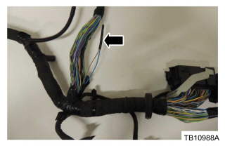
- Locate splice S129. (Figure 1)

Figure 1- Splice S129 has 3 circuits: gray/brown to engine sub loom, gray/brown to PCM, blue to turbocharger boost pressure (TCBP) sensor.
- Cut the wires on each side of splice S129 and strip 19 mm (3/4”) of insulation from each of the wires.
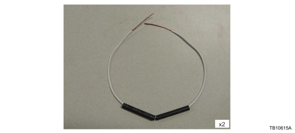
- Using the wire kit, prepare the wire for splicing as follows. (Figure 2)

Figure 2- Strip 38 mm (1 ½”) of insulation from each end of the wire.
- Position two (2) lengths of ES-1 double wall heat shrink tubing onto each wire.
- Join the two wires on the engine side of the harness with one end of the previously prepared 40.6 cm (16 in.) length of wire. Twist 13 mm (1/2”) of the ends of the wires together and bend the splice wire 90 degrees to the harness wire at the end of the twisted area. Solder the wires together using lead-free electrical solder, with the heat being applied opposite the applied solder.
- Repeat this step to join the single wire end of the splice S129 wire to the opposite end of the prepared wire.
- Position the heat shrink tubing over both ends of the splice wire. Using a suitable heat gun, such as Rotunda Shielded Flameless Heat Gun with Heat Deflector, NAIAT-R5902, that is equipped with a shrink tubing attachment, heat the heat shrink tubing until the sealant comes out of both ends.
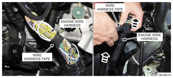
- Bundle the wires as shown and apply wire harness tape to the harness, starting from the bottom of the previously cut harness tape and working upward until all exposed wires are covered. (Figure 3)

Figure 3 - Reposition the wire harness.
- Reconnect the two wire harness retainers to the transmission side pan stud bolts and the TSS sensor.
- Install the air cleaner and air cleaner outlet pipe. Refer to WSM, Section 303-12.
- Install the engine appearance cover.
- Connect the battery ground cable. Refer to WSM, Section 414-01.
- Clear the DTCs.
| OPERATION | DESCRIPTION | TIME |
| 160161A | 2015-2016 Escape 1.6L GTDI: Check DTCs And Replace S129 Splices Includes Time To Access Splices (Do Not Use With Any Other Labor Operations) | 1.1 Hrs |
WARRANTY STATUS
Eligible Under Provisions Of New Vehicle Limited Warranty Coverage And Emissions Warranty Coverage.
Warranty/ESP coverage limits/policies/prior approvals are not altered by a TSB. Warranty/ESP coverage limits are determined by the identified causal part and verified using the OASIS part coverage tool.
DEALER CODING
| BASIC PART NO. | CONDITION CODE |
| 12A690 | 28 |


