
| “This site contains affiliate links for which OEMDTC may be compensated” |
NHTSA ID Number: 10168821
Manufacturer Communication Number: 18N03-S7
Summary
Customer Satisfaction Program 18N03 – Supplement #7
Certain 2015-2018 Model Year F-150 and 2017-2018 Model Year F-250-F-550
Vehicles – Door Latch Freezing Concerns
November 21, 2019
Customer Satisfaction Program 18N03 – Supplement #7
Certain 2015-2018 Model Year F-150 and 2017-2018 Model Year F-250-F-550
Vehicles – Door Latch Freezing Concerns
PROGRAM TERMS
This is a one-time repair program for vehicle owners that report a door latch freezing concern. Affected vehicles are eligible for this repair through October 31, 2028, regardless of vehicle mileage or warranty start date. Coverage is automatically transferred to subsequent owners. This program will expire October 31, 2028.
REASON FOR THIS SUPPLEMENT
Technical Information: Updated with revised directions regarding the inspection of the interior door handle release cables. As a result, the Labor Allowances and the Parts Requirements / Ordering Information have also been updated.
VEHICLES COVERED BY THIS PROGRAM
| Vehicle | Model Year | Assembly Plant | Build Dates |
| F-150 | 2015-2018 | Dearborn | March 12, 2014 through April 12, 2018 |
| Kansas City | August 11, 2014 through April 3, 2018 | ||
| F-250 – F-550 | 2017-2018 | Kentucky | October 8, 2015 through April 21, 2018 |
| OHAP | February 5, 2016 through April 17, 2018 |
REASON FOR PROVIDING EXTENDED WARRANTY COVERAGE
In the affected vehicles, water entering the doors in cold temperatures can cause door latching components to freeze. Ford is offering this no charge service to customers that have experienced a frozen door latch to install additional sealing to the front doors and crew cab rear doors, which will prevent water intrusion and door latch freezing.
SERVICE ACTION
If an affected vehicle owner has reported a frozen latch concern, dealers are to install additional sealing to the front doors and crew cab rear doors, lubricate certain door latch, door handle and cable components, clean the door drain holes, inject windshield wash concentrate or a methyl hydrate (methanol) product into the exterior door handle cables and install a wiper clip on the exterior door handle cable ends. This service must be performed at no charge to the vehicle owner.
Note: The technical instructions for this program include all additional steps required to also complete safety recall 17S33, if 17S33 is open.
OWNER NOTIFICATION AND MAILING SCHEDULE
Owners of affected vehicles have been notified. Dealers should repair any affected vehicles that experience a frozen door latch whether or not the customer has received a letter.
SOLD VEHICLES
- Only owners with affected vehicles that exhibit the covered condition will be directed to dealers for repairs.
- Dealers are to prioritize repairs of customer vehicles over repairs of new and used vehicle inventory.
STOCK VEHICLES
Do not perform this program unless the affected vehicle exhibits the covered condition.
TITLE BRANDED / SALVAGED VEHICLES
Affected title branded and salvaged vehicles are eligible for this service action.
OWNER REFUNDS
Refunds are not approved for this program.
RENTAL VEHICLES
The use of rental vehicles is not approved for this program.
PARTS REQUIREMENTS
| Description | Part Number | Order Quantity | Claim Quantity |
| Front Doors Foam Kit (F-150 Built Prior to December 2016*) | FL3Z-16308-L | As required | |
| Front Doors Foam Kit (F-150 Built December 2016 or later and All F-Super Duty*) (New Kit)*** | FL3Z-16308-P | As required | |
| Front Doors Foam Kit (F-150 Built December 2016 or later and All F-Super Duty*) (Old Kit)*** | FL3Z-16308-M | ||
| Rear Doors Foam Kit (crew cab only) (New Kit)*** | FL3Z-16308-Q | As required | |
| Rear Doors Foam Kit (crew cab only) (Old Kit)*** | FL3Z-16308-N | ||
| Exterior Door Handle Cable Wiper Clip (One Piece per Package) | LL3Z-15264B28-A | 2 Req. Reg/Sup Cab
4 Req. Crew Cab | |
| Motorcraft® Low Temperature Grease** | XG-16 | MISC. OTHER | |
| Motorcraft® Door Latch Grease** | XG-13 | ||
| Motorcraft® High Temperature Grease** | XG-11 | ||
| Motorcraft® Silicone Spray** | XL-6 | ||
| Motorcraft® Silicone Sealant** | TA-30 | ||
| Motorcraft® Premium Windshield Wash Concentrate, or a 99 percent Methyl Hydrate (Methanol) product** | ZC-32-B2 | ||
| Cotton Swabs/Q-Tips®** | Obtain Locally | ||
| Isopropyl Alcohol** | |||
| Brushes** | |||
| Syringe, Eye Dropper or a Similar Applicator | |||
| Description | Part Number | Order Quantity | Claim Quantity |
| Interior Door Handle Release Cable (RH Front – All Vehicles Except F-150 with Gas Engine) | HC3Z-15221A00-B | As required **** | |
| Interior Door Handle Release Cable
(LH Front – All Vehicles Except F-150 with Gas Engine) | HC3Z-15221A01-B | ||
| Interior Door Handle Release Cable
(LH/RH Front – Only F-150 with Gas Engine) | FL3Z-15221A00-B | ||
| Interior Door Handle Release Cable
(LH/RH Rear – All Vehicles Crew Cab Doors) | FL3Z-1540180-A | ||
**** Less than 5% vehicles are expected to require a cable replacement.
CERTAIN 2015-2018 MODEL YEAR F-150 AND 2017-2018 MODEL YEAR F-250 – F-550 VEHICLES — DOOR LATCH FREEZING CONCERNS
OVERVIEW
In the affected vehicles, water entering the doors in cold temperatures can cause door latching components to freeze. Ford is offering this no charge service to customers that have experienced a frozen door latch to install additional sealing to the front doors and crew cab rear doors, which will prevent water intrusion and door latch freezing. If an affected vehicle owner has reported a frozen latch concern, dealers are to install additional sealing to the front doors and crew cab rear doors, and lubricate certain door latch, door handle and cable components. This service must be performed at no charge to the vehicle owner.
NOTE: The technical instructions for this program include all additional steps required to also complete safety recall 17S33, if 17S33 is open.
NOTE: Please read this procedure in its entirety, prior to performing repairs. Additionally, instructional videos have been developed to assist with the repair. Please refer to Attachment IV: Instructional Video Links to view the videos.
NOTE: Some of the door foam kits were packaged with incorrect size door glass run funnels. Prior to starting the repair, please refer to ATTACHMENT V – Door Glass Run Funnel Measurement Guide, to ensure the correct funnels are being installed.
SERVICE PROCEDURE
Recommended Tool List:
| General Tools | General Equipment |
| 1/4″ Drive Impact Driver | Flashlight |
| 1/4″ Drive Ratchet | Industrial Grade Heavy Duty Scissors |
| 1/4″ Drive Torque Wrench | Bungee Cords |
| 1/4″ Drive Extension – 6″ (152mm) | Body Tape |
| 1/4″ Drive Socket – 7mm, 8mm and 10mm | Q-Tips® |
| 1/4″ Driver Bit – T-20 and T-25 Torx® | Brushes |
| 3/8″ Drive Ratchet | Caulk Gun |
| 3/8″ Driver Bit – T-30 Torx® | Ruler |
| 3/8″ Drive Torque Wrench | Paint Pen |
| Small Pick | Locally Obtained Syringe, Eye Dropper or Similar Applicator |
| Plastic Trim Removal Tools | Disposable Gloves |
| Pocket Screwdriver | Shop Towel |
| Blowgun | Zip Tie |
| Long Needle Nose Pliers | |
| Utility Knife | |
| 10mm Wrench | |
| Tape Measure |
Front Door Service Procedure
- Is this a F-150 vehicle with safety recall 17S33 open?
Yes – Proceed to the Front Door Latch Water Shield Kit installation Procedure.
No – Proceed to the Front Door and Front Door Latch Sealing Procedure (Page 9).
Front Door Latch Water Shield Kit Installation (Safety Recall 17S33 Open)
NOTE: Front door latch water shields were phased into F-150 production in December 2016.
For vehicles already equipped with water shields, it is not necessary to remove and replace the water shields on the front doors.
NOTE: This procedure uses a different door latch water shield attachment procedure than what was previously used in TSB 16-0155. Do not attempt to use TSB parts to perform this procedure.
NOTE: Procedure to be performed on both front doors.
NOTE: The window must be in the closed (up) position when performing this procedure.
NOTICE: Do not allow the door trim panel or exterior door handle to hang by the door handle cables or damage to the cable and door may occur.
- Remove the exterior front door handles. Please follow the Workshop Manual (WSM) procedures in Section 501-14.
NOTE: The interior grab handle cover clips can be reused for this repair. Only replace if damaged.
- Remove the lock rod assemblies. See Figure 1.
- Use the male end of a 1/4″ extension to spread apart the lock rod retainer and remove the rod from the door latch.
NOTE: Driver door latch shown, passenger door latch similar.

FIGURE 1
- Through the exterior front door handle opening, inspect for a rubber water shield installed on top of the door latch. See Figure 2.
- If a rubber water shield is present, remove and discard the two attaching clips and the rubber water shield.
- Clean the surface area where the water shield covered with isopropyl alcohol and a clean shop cloth. Use part of the center portion of Foam E (refer to Figure 12) or some locally acquired body tape to seal the holes the attaching clips were previously installed in. See Figure 3.
NOTE: Driver door latch shown, passenger door latch similar.

FIGURE 2

FIGURE 3
- Remove and discard the rubber drain plug and clean any obstructions, debris, foreign material and residual water from all of the door drain holes using compressed air and a tool such as a plastic trim tool or a zip tie. See Figure 4.
NOTE: Front passenger door shown, all doors similar.

FIGURE 4
- Using compressed air, blow out any debris or residual water from the door latch assembly, exterior door handle mechanism and cables for thirty seconds. Blow drying with compressed air for thirty seconds is critical to remove as much moisture as possible. See Figure 5.
NOTE: Driver rear door latch shown, all door latches similar.

FIGURE 5
- Loosen but do not remove the two door glass run bolts. See Figure 6.

FIGURE 6
- Loosen but do not remove the 3 door latch bolts. See Figure 7.

FIGURE 7
- Apply supplied Foam Tape to the new water shield in the highlighted area. See Figure 8.

FIGURE 8
- With the latch and door glass run assembly loose inside the door panel, install the door latch water shield into position. See Figure 9.
NOTE: The water shield is properly installed when the locating tabs align with the door glass run, the latch cable is fitted in the notch of the water shield, and the fastener holes align.
- Install the new screw into the top hole of the shield. See Figure 9.
NOTE: The lower fastener hole of the shield is not used on the front water shields.
NOTE: Driver door latch shown, passenger door latch similar.

FIGURE 9
- Tighten the two door glass run bolts. See Figure 6.
- 8 Nm (71 lb.in).
- Tighten the three door latch bolts. See Figure 7.
- 8 Nm (71 lb.in).
- Refer to Figure 10 to determine if the door latch is equipped with the new style lock rod.
NOTE: The new style lock rod is required to accommodate the water shield.
- Is the door latch equipped with the new style lock rod?
- Yes – Reinstall the lock rod and proceed to the Front Door and Front Door Latch Sealing
Procedure (Page 9). - No – Proceed to Step 17.
- Yes – Reinstall the lock rod and proceed to the Front Door and Front Door Latch Sealing

FIGURE 10
NOTE: If a replacement lock rod already has a button and grommet installed, transfer of the components is not required.
- Replace the lock rod and transfer the necessary components. See Figure 11.
a. Transfer the grommet and button from the original lock rod to the new lock rod.
b. Apply a bead of Motorcraft® Instant Gel Adhesive TA-19-C or equivalent to the lock rod prior to threading the button onto the new lock rod.
c. When threading the button onto the new lock rod, stop threading when some resistance is met.
d. Ensure both front lock rod buttons are installed at similar heights.
e. Reinstall the lock rod.
NOTE: Driver door latch shown, passenger door latch similar.

FIGURE 11
- Proceed to the Front Door and Front Door Latch Sealing Procedure.
Front Door and Front Door Latch Sealing Procedure
IMPORTANT! There are two different front door foam kits available for the F-150 vehicles. One kit comes with short (65mm funnel wings) door glass funnels (built before December 2016), and the other kit comes with long (157mm funnel wings) door glass funnels (built December 2016 or later). Funnel usage is based on vehicle build date and the length of the door glass run installed. Only one front door foam kit is available for the F-250-F-550 vehicles and the kit contains long (157mm funnel wings) door glass funnels. Refer to Attachment V for additional information.
NOTE: Procedure to be performed on both front doors.
Complete Front Door Part Kit – Each Kit Will Include Either Long Door Glass Run Funnels Or Short Door Glass Run Funnels

FIGURE 12
NOTE: The parts being installed in this procedure are not labeled. Refer to Figure 12 for component identification.
NOTE: These components will be used for the following procedures:
- Front Door Glass Run and Belt Moulding Sealing Procedure (All Vehicles)
- Front Door Latch and Handle Service Procedure (All Vehicles)
Front Door Glass Run and Belt Moulding Sealing Procedure (All Vehicles)
Front Door Glass Run and Belt Moulding Sealing Components

FIGURE 13
NOTE: Procedure to be performed on both front doors.
NOTE: The window must be in the closed (up) position when performing this procedure.
NOTICE: Do not allow the door trim panel or exterior door handle to hang by the door handle
cables or damage to the cable and door may occur.
- Remove the exterior front door handles. Please follow the Workshop Manual (WSM) procedures in Section 501-14.
NOTE: The interior grab handle cover clips can be reused for this repair. Only replace if damaged.
- If a cable wiper clip is present on the exterior door handle cable end, remove and discard the cable wiper clip. See Figure 14.

FIGURE 14
- Inspect the interior door handle to latch release cable for kinking. See Figure 15.
– Were any kinks visible on the interior door handle release cable?
Yes – Continue to Step 4.
No – Proceed to Step 6.

FIGURE 15
NOTE: The front door latch of some vehicles is equipped with a small flexible plastic water shield located over the exterior door handle cable attachment point. Note the water shield position and orientation for reassembly. See Figure 16.
NOTE: Certain vehicles are equipped with an interior door handle release cable retaining bracket on the front door latch. The interior door handle release cable is serviced in a similar manner whether or not a cable retaining bracket is present. See Figure 16.

FIGURE 16
NOTE: It is not necessary to detach the exterior door handle cable from the retaining bracket or remove the exterior door handle cable from the latch.
- Remove the front door latch and install a new interior door handle release cable. Please follow the WSM procedures in Section 501-14.
CAUTION: Use caution not to kink the cables during reassembly of the door latch. NOTE: Do not reinstall the door panel, watershield or the exterior door handle at this time.
- Reassemble and reinstall the front door latch. Complete by reversing the WSM procedures in Section 501-14. Then proceed to Step 6.
- If water shield kit installation was not necessary, remove and discard the rubber drain plug and clean any obstructions, debris, foreign material and residual water from all of the door drain holes using compressed air and a plastic trim tool. See Figure 17.
NOTE: Front passenger door shown, all doors similar.
FIGURE 17
- If not previously performed, use compressed air and blow out any debris or residual water from the door latch assembly, exterior door handle mechanism and cables for thirty seconds. Blow drying with compressed air for thirty seconds is critical to remove as much moisture as possible. See Figure 18.
NOTE: Driver rear door latch shown, all door latches similar.
FIGURE 18
- Position the front door window glass down.
- Remove the inner belt moulding and position aside the latch side of the door glass top run.
See Figure 19.

FIGURE 19
- If present, remove and discard existing foam on the driver and passenger side outer belt moulding (also known as upper belt moulding) at this location. See Figure 20.
NOTE: Passenger door shown, driver door similar.

FIGURE 20
- Clean the highlighted area of the outer belt moulding with isopropyl alcohol and a clean shop cloth.
See Figure 21.

FIGURE 21
- Apply a small bead of Motorcraft® TA-30 Silicone sealant onto the highlighted area of the outer belt moulding, ensuring the two belt moulding clips shown in Figures 21 and 22 are completely covered. Using your finger, smooth out the sealer to establish an even surface. See Figure 22.
NOTE: A proper seal around the belt moulding metal clips is necessary to prevent water from entering the door.

FIGURE 22
- Using a small trim removal tool, install Foam A to the outer belt moulding on top of the bead of silicone that was previously applied. Both of the outer belt moulding clips need to be covered by the Foam A. See Figures 23 and 23.
NOTE: It is crucial that both outer belt moulding clips are covered by Foam A and that the end of Foam A wraps around the outer belt moulding as shown.

FIGURE 22

FIGURE 24
- Remove any excessive silicone in visible areas on the outer belt moulding with isopropyl alcohol and a clean shop cloth.
- Modify the front door glass top run. See Figure 25.
a. Measure 15 mm (9/16 in) from the inboard bottom corner of the door glass top run.
b. Mark the 15 mm (9/16 in) location.
c. Starting at the bottom outboard corner of the door glass top run, cut a 45° notch using the previous measurement as a guide.

FIGURE 25
- Install one of the appropriate length door glass run funnels ensuring that the lower tab is situated in the door glass run and the funnel sides sit at a 90° angle above the door glass run. See Figure 26. Refer to Attachment V for additional information.
- F-150 vehicles: Short funnels – 65mm funnel wings (built before December 2016), Long funnels
– 157mm funnel wings (built December 2016 or later) - F-250-F-550 vehicles: Long funnels only – 157mm funnel wings
- F-150 vehicles: Short funnels – 65mm funnel wings (built before December 2016), Long funnels
NOTE: Ensure the funnel sides are at a 90° angle upon installation. It may be necessary to bend the sides of the funnel back to a 90° angle before installation.

FIGURE 26
- Reinstall the latch side of the front door glass top run and the inner belt moulding. See Figure 19.
NOTICE: IT WILL BE NECESSARY TO HOLD THE UPPER PORTION OF THE FUNNEL WHEN INSTALLING THE DOOR GLASS TOP RUN. CARE MUST BE TAKEN TO NOT BEND OR DAMAGE THE DOOR GLASS RUN FUNNEL.
- Unseat the front door lock rod grommet and visually confirm that the funnel is in the correct position and then reinstall the front door lock rod grommet. See Figure 27.
NOTE: Driver door lock rod grommet shown, passenger door lock rod grommet similar.

FIGURE 27
- Raise the front door window to the full up position.
- Using your hand install the Foam Tape on the top of the door glass run and on the back of the door glass run funnel in the order shown in Figure 28. Figure 29 shows the Foam Tape installed.

FIGURE 28
NOTE: Front door shown, rear door similar.

FIGURE 29
- Using isopropyl alcohol clean the top portion of the door and then neatly apply Motorcraft® TA-30 silicone sealant to the indicated/highlighted area in order to completely fill the gap as shown in Figure 30.
- Do not close the door until the silicone is cured.
NOTE: Proper application of the sealant is crucial to properly water seal the door and also avoid appearance concerns.
NOTE: Top of driver front door shown, passenger front door similar.

FIGURE 30
- Modify the front door lock rod grommet. See Figure 31.
a. Using a utility knife, cut four 6 mm (.25 in) long slits approximately 90° apart into the top of the front door lock rod grommet where the lock rod exits the grommet.
b. Cut four additional 13 mm (.5 in) long slits approximately 90° apart on the inner sides of the grommet 45° separated from the previously cut slits.

FIGURE 31
- Proceed to the Front Door Latch and Exterior Handle Service Procedure.
Front Door Latch and Exterior Handle Service Procedure (All Vehicles)
NOTE: Procedure to be performed on both front doors.
Front Door Latch and Exterior Handle Sealing Components

FIGURE 32
- For driver door latch only, attach Foam G to Foam H. See Figure 33.

FIGURE 33
- Install Foam H onto the driver door latch. See Figure 34.
NOTE: Driver door latch shown with Foam G and H, Passenger door latch similar with Foam B.

FIGURE 34
- Install Foam D over the door latch cable and onto Foam H (driver door) and Foam B (passenger door) to cover the gap between the cable and Foam H. See Figure 35.
- The notch of Foam D must point downwards when installed.
NOTE: Driver door latch shown with Foam G and H, Passenger door latch similar with Foam B.

FIGURE 35
- Using a trim tool, install Foam C onto the top of the front door latch water shield.
NOTE: For the taller style window runs refer to Figure 36a and for the shorter style window runs with a shoulder and a cable retaining clip refer to Figure 36b.
NOTE: Driver door latch shown, passenger door latch similar.

FIGURE 36a

FIGURE 36b
- Using a trim tool, install Foam F between the water shield and the door glass run. See Figure 37.
NOTE: Do not remove the adhesive backing from Foam F and install Foam F with the adhesive backing facing downward.
NOTE: Driver door shown, passenger door similar.

FIGURE 37
- For driver side only, apply Motorcraft® XG-13 grease to the area where the key lock rod attaches to the key lock rod lever. See Figure 38.
- For driver side only, install the rubber grommet onto the key lock rod over the key lock rod lever. The rubber grommet should be positioned as shown. The rubber grommet will sit sideways when installed properly. See Figure 38.
NOTE: Door latch assembly shown out of vehicle for clarity.

FIGURE 38
- Apply XG-11 grease on top of and around Foam D after Foam D is installed. The Foam D notch, the gap between the cable and Foam D, and the gap between the door glass run and Foam H must be covered with grease. See Figure 39.
NOTE: Do not allow the XG-11 grease to come into contact with moving components of the latch mechanism.
NOTE: Driver door shown, passenger door similar.

FIGURE 39
- If equipped, disconnect the interior door handle cable retaining clips from the door sheet metal.
- Using isopropyl alcohol and a clean shop cloth, throughly remove grease from the interior door handle cable mechanism. See Figure 40.

FIGURE 40
- Unseat the interior door handle cable rubber grommet and while holding the end of the cable in an upward position, spray Motorcraft® XL-6 Lubricant down into the cable for five seconds. See Figure 41.
NOTE: If the Motorcraft® XL-6 Lubricant container is not equipped with an applicator nozzle that can accommodate a straw, swap the applicator nozzle from another Motorcraft® chemical such as: XL-5 Multi-Purpose Grease Spray, XL-5-A Multi-Purpose Grease Spray or ZC-30-A Silicone Gasket Remover so a straw can be used. Spray a small amount to clear the applicator nozzle and straw prior to spraying the cable.

FIGURE 41
- Using a bungee cord or other similar device, secure the interior door handle cable to the door in an upward position to allow the Motorcraft® XL-6 Lubricant time to run down into the cable, until the interior door handle cable is reinstalled later in this procedure. See Figure 42.

FIGURE 42
NOTE: The use of disposable gloves is required.
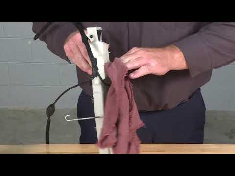
- Towel dry the exterior door handle cable to absorb any residual moisture. Using a bungee cord or other similar device secure the exterior door handle cable to the door in an upward position as shown in Figure 42, to allow the undiluted Motorcraft® Premium Windshield Wash Concentrate (ZC-32-B2) or a 99 percent methyl hydrate (methanol) product time to run down into the cable, until the exterior door handle cable is reinstalled later in this procedure.
- Using a locally obtained syringe, eye dropper or a similar applicator draw 10 ml of the undiluted Motorcraft® ZC-32-B2 Concentrate or a 99 percent methyl hydrate (methanol) product into the applicator. With the cable pulled out and the tip of the applicator positioned inside the arrowhead cable end fitting inject 2 ml between the cable shield and the cable then cycle the cable 5 times in and out of the cable shield. Repeat injecting fluid and cycling the cable a total of 5 times.
NOTICE: Place a shop towel around the exterior door handle cable, while performing this procedure, to prevent dripping onto the vehicle which could cause paint damage.
NOTE: Do not use a product that contains isopropyl alcohol. Only use a product containing methanol or a mix of methanol and ethylene glycol.
NOTE: Rear door shown, front door similar.

FIGURE 43
- Using a clean shop cloth and isopropyl alcohol, clean the highlighted mating surface area of the exterior front door handle. See Figure 44.

FIGURE 44
- Using a clean shop cloth and isopropyl alcohol clean inside the dotted lines on the mating surface area of the front exterior door handle openings. See Figure 45.

FIGURE 45
- Install Foam E around the perimeter of the exterior door handle on top of the existing seal.
NOTE: Foam E will not wrap around the entire perimeter of the exterior door handle.
NOTE: Proper placement of Foam E is crucial for proper sealing and to avoid appearance concerns.
A. Lay out Foam E on the exterior door handle and mark center as shown in Figure 46.
B. Remove Foam E from the door handle and remove the back center portion of the adhesive backing then cut the protective backing in half. See Figure 46.
C. Align the marks made on the Foam E and exterior door handle and adhere the back center portion to the exterior door handle as shown in Figure 47.
D. Lay one side of Foam E down on the exterior door handle and without stretching the foam pull off the adhesive backing as you adhere Foam E to the exterior door handle as shown in Figure 47.
E. Remove the protective backing from the other side of Foam E as shown in Figure 47.
F. Without stretching the foam adhere it to the exterior door handle ensuring that both sides of Foam E are of equal length once secured. See Figure 48.

FIGURE 46

FIGURE 47

FIGURE 48
- Using a clean shop cloth and isopropyl alcohol, clean the handle plunger then using a brush apply a light film of Motorcraft® XG-16 low temperature grease to all four sides of the exterior door handle plunger and to the mechanisms in the areas shown in Figures 49 and 50.

FIGURE 49

FIGURE 50
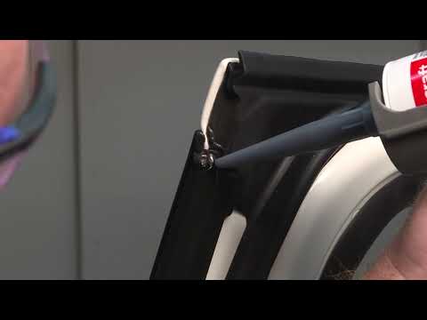
- Apply a bead of Motorcraft® TA-30 silicone sealant to the latch side area of the front door exterior handle opening making sure that the sealant will overlap with the Foam E on the exterior door handle. See Figure 51.
NOTE: Proper placement of the Motorcraft® TA-30 silicone sealant is crucial for proper sealing and to avoid appearance concerns.
NOTE: Driver door shown, passenger door similar.

FIGURE 51
- Remove the bungee cords used to hold the interior and exterior door handle cables up, seat the rubber grommet and if equipped, reinstall the interior door handle cable retaining clips.
- Reconnect the exterior door handle cable to the door handle, then lubricate the door handle cable end with Motorcraft® XG-16 low temperature grease, as shown in Figure 52.

FIGURE 52
- Install a new handle cable wiper clip on the exterior door handle cable end. See Figure 53.

FIGURE 53
- Reinstall the front exterior door handles. Please follow the WSM procedures in Section 501-14.
NOTICE: Reinstall the exterior door handle cable and retaining clips in the original factory position.
- Clean any excessive silicone around the exterior door handle perimeter with isopropyl alcohol, Q-tips® and a clean shop cloth to avoid appearance concerns.
- Determine next steps based on vehicle and cab configuration.
- For all Regular Cab vehicles, F-150 Super Cab vehicles without safety recall 17S33 open, and all F-250-F-550 Super Cab vehicles, the repair is complete.
- For all Crew Cab vehicles, proceed to the Rear Door Service Procedure (Page 38).
- For F-150 Super Cab vehicles with safety recall 17S33 open, proceed to the Rear Door Lower Latch Water Shield Kit Installation Procedure (Page 69).
Rear Door Service Procedure (Crew Cab Vehicles)
- Is safety recall 17S33 open?
- Yes – Proceed to the Rear Door Latch Water Shield Kit Installation Procedure (Crew Cab Vehicles).
- No – Proceed to the Rear Door Glass Run and Belt Moulding Sealing Procedure (Crew Cab Vehicles). (Page 42)
Rear Door Latch Water Shield Kit Installation Procedure (Crew Cab Vehicles With Safety Recall 17S33 Open)
NOTE: This procedure uses a different door latch water shield attachment procedure than what was previously used in TSB 16-0155. Do not attempt to use TSB parts to perform this procedure.
NOTE: Procedure to be performed on both rear doors.
NOTE: The window must be in the closed (up) position when performing this procedure.
NOTICE: Do not allow the door trim panel or exterior door handle to hang by the door handle cables or damage to the cable and door may occur.
- Remove the exterior rear door handles. Please follow the WSM procedures in Section 501-14.
NOTE: The interior grab handle cover clips can be reused for this repair. Only replace if damaged.
- Remove the lock rod assembly from the rear door latch. See Figure 54.
- Use the male end of a 1/4″ extension to spread apart the lock rod retainer and remove the rod from the door latch.
NOTE: Driver door latch shown, passenger door latch similar.

FIGURE 54
- Remove and discard the rubber drain plug and clean any obstructions, debris, foreign material and residual water from all of the door drain holes using compressed air and a tool such as a plastic trim tool or a zip tie. See Figure 55.
NOTE: Front passenger door shown, all doors similar.
FIGURE 55
- Using compressed air, blow out any debris or residual water from the door latch assembly, exterior door handle mechanism and cables for thirty seconds. Blow drying with compressed air for thirty seconds is critical to remove as much moisture as possible. See Figure 56.
NOTE: Driver door latch shown, passenger door latch similar.
FIGURE 56
- Install the door latch water shield into position. See Figure 57.
NOTE: The water shield is properly installed when the latch cable is fitted in the notch of the water shield and the fastener holes align.
- Install the new screws into the top and bottom holes of the shield. See Figure 57.
NOTE: Driver door latch shown, passenger door latch similar.

FIGURE 57
- Refer to Figure 58 to determine if the door latch is equipped with the new style lock rod.
Is the door latch equipped with the new style lock rod or manual locks?
Yes – Reinstall the lock rod if equipped and proceed to the Rear Door Glass Run and Belt Moulding Sealing Procedure (Page 42).
No – Proceed to Step 8.

FIGURE 58
- Lock rod replacement procedure. See Figure 59.
NOTE: If a replacement lock rod already has a button and grommet installed, transfer of the components is not required.
a. Transfer the grommet, sleeve and button from the original lock rod to the new lock rod.
b. Apply a bead of Motorcraft® Instant Gel Adhesive TA-19-C or equivalent to the lock rod prior to threading the button onto the new lock rod.
c. When threading the button onto the new lock rod, stop threading when some resistance is met.
d. Ensure both rear lock rod buttons are installed at similar heights.
e. Reinstall the lock rod.
NOTE: Driver door latch shown, passenger door latch similar.

FIGURE 59
- Proceed to the Rear Door Glass Run and Belt Moulding Sealing Procedure (Page 42).
Rear Door Glass Run and Belt Moulding Sealing Procedure (Crew Cab Vehicles)
Complete Rear Door Part Kit

FIGURE 60
NOTE: The parts being installed in this procedure are not labeled. Refer to Figure 60 for component identification.
Rear Door Glass Run and Belt Moulding Sealing Components
NOTE: Procedure to be performed on both rear doors.

FIGURE 61
NOTE: Procedure to be performed on both rear doors.
NOTE: The window must be in the closed (up) position when performing this procedure.
NOTICE: Do not allow the door trim panel or exterior door handle to hang by the door handle cables or damage to the cable and door may occur.
- Remove the exterior rear door handles. Please follow the Workshop Manual (WSM) procedures in Section 501-14.
NOTE: The interior grab handle cover clips can be reused for this repair. Only replace if damaged.
- If a cable wiper clip is present on the exterior door handle cable end, remove and discard the cable wiper clip. See Figure 62.
NOTE: Front exterior door handle shown, all exterior door handles similar.
FIGURE 62
- Inspect the interior door handle to latch release cable for kinking. See Figure 63.
– Were any kinks visible on the interior door handle release cable?
Yes – Proceed to Step 4.
No – Proceed to Step 6.

FIGURE 63
NOTE: It is not necessary to detach the exterior door handle cable from the retaining bracket or remove the exterior door handle cable from the latch.
- Remove the rear door latch and install a new interior door handle release cable. Please follow the WSM procedures in Section 501-14.
CAUTION: Use caution not to kink the cables during reassembly of the door latch. NOTE: Do not reinstall the door panel, watershield or the exterior door handle at this time.
- Reassemble and reinstall the rear door latch. Complete by reversing the WSM procedures in Section 501-14. Then proceed to Step 6.
- If water shield kit installation was not necessary, remove and discard the rubber drain plug and clean any obstructions, debris, foreign material and residual water from all of the door drain holes using compressed air and a tool such as a plastic trim tool or a zip tie. See Figure 64.
NOTE: Front passenger door shown, all doors similar.
FIGURE 64
- If not previously performed, use compressed air and blow out any debris or residual water from the
door latch assembly, exterior door handle mechanism and cables for thirty seconds. Blow drying with
compressed air for thirty seconds is critical to remove as much moisture as possible. See Figure 65.
NOTE: Driver front door latch shown, all door latches similar.
FIGURE 65
- Position the rear door window glass down.
- Remove the rear door inner belt moulding and position aside the latch side of the door glass top run. See Figure 66.

FIGURE 66
- If present, remove and discard the foam on the door outer belt moulding at the location shown in Figure 67.

FIGURE 67
- Clean the highlighted area of the outer belt moulding with isopropyl alcohol and a clean shop cloth. See Figure 68.
NOTE: Make sure to clean past the second clip.

FIGURE 68
- Apply Motorcraft® TA-30 silicone sealer to the area highlighted on the outer belt moulding. Using your finger, smooth out the sealer to establish an even surface. See Figures 69 and 70.
NOTE: Completely covering the belt moulding metal clips is crucial for proper sealing. See Figure 70.

FIGURE 69

FIGURE 70
- Install Foam H to the C-pillar end of the outer belt moulding. See Figure 71.

FIGURE 71
- Remove any excessive silicone in visible areas on the outer belt moulding with isopropyl alcohol and a clean shop cloth.
- Modify the rear door glass top run. See Figure 72.
a. Measure 15 mm (9/16 in) from the inboard bottom corner of the door glass top run.
b. Starting at the bottom outboard corner of the rear door glass top run, cut a 45° notch using the previous measurement as a guide.

FIGURE 72
- If present, remove and discard the felt on the rear door glass top run. See Figure 73.

FIGURE 73
- Clean the highlighted area of the rear door glass top run with isopropyl alcohol and a clean shop cloth. See Figure 74.

FIGURE 74
- Install Foam N to the highlighted area of rear door glass top run making sure that the Foam N is under the C-Pillar notch. See Figure 74.

FIGURE 74
- With the rear door latch side door glass top run still positioned aside raise the rear door window glass three quarters of the way up. See Figure 76.
NOTICE: Use care when raising window glass to not pinch door glass top run or scratch the glass.

FIGURE 76
- Modify the rear door lock rod grommet. See Figure 77.
a. Remove the rear door lock rod grommet from the lock rod.
b. Cut approximately 6 mm (0.25 in)off the top of the grommet.
c. Install the rear door lock rod grommet back onto the lock rod.
d. Using a utility knife, cut four 6 mm (0.25 in) long slits approximately 90° apart into the lower portion of the rear door lock rod grommet.

FIGURE 77
- Proceed to the Rear Door Latch and Handle Service Procedure.
Rear Door Latch and Handle Service Procedure (Crew Cab Vehicles)
Rear Door Latch and Handle Sealing Components
NOTE: Procedure to be performed on both rear doors.

FIGURE 78
- Install Foam J onto the rear door latch. See Figure 79.
NOTE: Driver door latch shown, passenger door latch similar.

FIGURE 79
- Install Foam L over the door latch cable and onto Foam J to cover the gap between the exterior door latch cable and Foam J. See Figure 80.
- The notch of foam L must point downward when installed.
NOTE: Driver door latch shown, passenger door latch similar.

FIGURE 80
- Clean the highlighted area on top of the door latch water shield with isopropyl alcohol and a clean shop cloth where the Foam Tape 2 will be installed. See Figure 81.
NOTE: Driver door latch shown, passenger door latch similar.

FIGURE 81
- Install Foam Tape 2 on top of the rear door latch water shield. See Figures 82.
- Make sure that Foam Tape 2 attaches to the water shield and to the door glass run.
NOTE: Driver door latch shown, passenger door latch similar.

FIGURE 82
- Install Foam I to cover the gap between the rear door latch assembly water shield and the door glass run. See Figure 83.
NOTE: Driver door latch shown, passenger door latch similar.

FIGURE 83
- Apply Motorcraft® TA-30 silicone sealant in and over the mating area of the water shields to the door. Using light finger pressure smooth the bead of silicone. See Figure 84.

FIGURE 84
- Position the rear door window glass down.
- Install the door glass run funnel (132mm funnel wings), ensuring the lower tab is situated in the door glass run and the funnel sides sit at a 90° angle above the door glass run. Refer to Attachment V for additional information. See Figure 85.
NOTE: Verify the sides of the funnel are bent to 90° prior to installation.

FIGURE 85
- Install the rear door glass top run and inner belt moulding. See Figure 66.
NOTICE: When installing the rear door glass top run make sure not to bend or damage the door glass run funnel. Check through the exterior door handle opening to verify that the funnel is positioned correctly.
- Position the rear door window glass up.
- Apply supplied Foam Tape 1 in the location shown to hold the funnel in place. See Figure 86.

FIGURE 86
- Apply XG-11 grease on top of and around Foam L. The Foam L notch, the gap around the cable and Foam L, and the gap between the door latch assembly and Foam J must be filled with grease. See Figure 87.
NOTE: Do not allow the XG-11 grease to come into contact with moving components of the latch mechanism.

FIGURE 87
- Using isopropyl alcohol and a clean shop cloth, throughly remove grease from the interior door handle cable mechanism. See Figure 88.
FIGURE 88
- Unseat the interior door handle cable rubber grommet and while holding the end of the interior door handle cable in an upward position, spray Motorcraft® XL-6 Lubricant for five seconds down into the cable. See Figure 89.
NOTE: If the Motorcraft® XL-6 Lubricant container is not equipped with an applicator nozzle that can accommodate a straw, swap the applicator nozzle from another Motorcraft® chemical such as: XL-5 Multi-Purpose Grease Spray, XL-5-A Multi-Purpose Grease Spray or ZC-30-A Silicone Gasket Remover so a straw can be used. Spray a small amount to clear the applicator nozzle and straw prior to spraying the cable.

FIGURE 89
- Using a bungee cord or other similar device, secure the interior door handle cable to the door in an upward position to allow the lubricant time to run down into the cable, until the interior door handle cable is reinstalled later in this procedure. See Figure 90.

FIGURE 90
NOTE: The use of disposable gloves is required.
- Towel dry the exterior door handle cable to absorb any residual moisture. Using a bungee cord or other similar device secure the exterior door handle cable to the door in an upward position as shown in Figure 91, to allow the undiluted Motorcraft® Premium Windshield Wash Concentrate (ZC-32-B2) or a 99 percent methyl hydrate (methanol) product time to run down into the cable, until the exterior door handle cable is reinstalled later in this procedure.
- Using a locally obtained syringe, eye dropper or a similar applicator draw 10 ml of the undiluted Motorcraft® ZC-32-B2 Concentrate or a 99 percent methyl hydrate (methanol) product into the applicator. With the cable pulled out and the tip of the applicator positioned inside the arrowhead cable end fitting inject 2 ml between the cable shield and the cable then cycle the cable 5 times in and out of the cable shield. Repeat injecting fluid and cycling the cable a total of 5 times.
NOTICE: Place a shop towel around the exterior door handle cable, while performing this procedure, to prevent dripping onto the vehicle which could cause paint damage.
NOTE: Do not use a product that contains isopropyl alcohol. Only use a product containing methanol or a mix of methanol and ethylene glycol.
FIGURE 91
- Using a clean shop cloth and isopropyl alcohol, clean the highlighted mating surface area of the exterior door handle. See Figure 92.

FIGURE 92
- Using a clean shop cloth and isopropyl alcohol, clean inside the dotted lines on the mating surface area of the exterior door handle opening. See Figure 93.

FIGURE 93
- Install Foam K around the perimeter of the exterior door handle on top of the existing seal.
NOTE: Foam K will not wrap around the entire perimeter of the exterior door handle.
NOTE: Proper placement of Foam K is crucial for proper sealing and to avoid appearance concerns.
A. Lay out Foam K on the exterior door handle and mark center as shown in Figure 94.
B. Remove Foam K from the door handle and remove the back center portion of the adhesive backing then cut the protective backing in half. See Figure 94.
C. Align the marks made on the Foam K and exterior door handle and adhere the back center portion to the exterior door handle as shown in Figure 95.
D. Lay one side of Foam K down on the exterior door handle and without stretching the foam pull off the adhesive backing as you adhere Foam K to the exterior door handle as shown in Figure 95.
E. Remove the protective backing from the other side leg of Foam K as shown in Figure 95.
F. Without stretching the foam adhere it to the exterior door handle ensuring that both sides of Foam K are of equal length once secured. See Figure 96.

FIGURE 94
FIGURE 95

FIGURE 96
- Using a clean shop cloth and isopropyl alcohol, clean the handle plunger then, using a brush, apply a light film of Motorcraft® XG-16 low temperature grease to all four sides of the exterior door handle plunger and to the mechanisms in the areas shown in Figures 97 and 98.
FIGURE 97

FIGURE 98
- Apply a bead of Motorcraft® TA-30 silicone sealant to the rear vertical area of the rear door metal surface making sure that the sealant will overlap with the Foam K on the exterior door handle.
See Figure 99.
NOTE: Proper placement of the Motorcraft® TA-30 silicone sealant is crucial to ensure proper sealing and avoid appearance concerns.
NOTE: Driver door shown, passenger door similar.

FIGURE 99
- Remove the bungee cords used to hold the interior and exterior door handle cables up and seat the interior door handle cable rubber grommet.
- Reconnect the exterior door handle cable to the door handle, then lubricate the door handle cable end with XG-16 low temperature grease as shown in Figure 100.

FIGURE 100
- Install a new handle cable wiper clip on the exterior door handle cable end. See Figure 101.
FIGURE 101
- Reinstall the rear exterior door handles. Please follow the WSM procedures in Section 501-14.
NOTICE: Reinstall the exterior door handle cable and retaining clips in the original factory position.
- Clean any excessive silicone around the exterior door handle perimeter with isopropyl alcohol, Q-tips and a clean shop cloth to avoid appearance concerns.
Crew Cab vehicle repair is complete.
Rear Door Lower Latch Water Shield Kit Installation (F-150 Super Cab Vehicles With Safety Recall 17S33 Open)
NOTE: If the vehicle has previously had a rear lower door latch replaced, it may already have the latest level door latch water shield installed. If the Super Cab rear lower door latch has a large water shield installed as shown in Figure 105, then installation of a new water shield is not required.
NOTE: Procedure to be performed on both rear doors.
- Remove the rear door interior trim panels. Please follow the WSM procedures in Section 501-05.
- Remove the door panel weather shield for access. See Figure 102.
- Using compressed air, blow out any debris or residual water from the latch assembly area. See Figure 102.

FIGURE 102
- Inspect the interior door handle to latch cable for kinking. See Figure 104.
- Correct any kinks found in the cable by straightening the cable by hand as required.
- Remove the three lower door latch bolts. See Figure 103.

FIGURE 103
- Detach the cable retainers and disconnect the electrical connector. Position the rear door latch outside of the door. See Figure 104.

FIGURE 104
NOTE: Some F-150 SuperCab vehicles may be equipped with a smaller water shield than what is being installed in this program. The smaller shields must be removed and replaced. See Figure 105.
- If equipped with small water shields, remove and discard the existing lower door latch water shields.
See Figure 105.

FIGURE 105
- Install a new door latch water shield onto the lower rear door latch. See Figure 106.

FIGURE 106
- Position the rear door lower latch back into the door. Attach the cable retainers and connect the electrical connector. See Figure 103.
- Install the three lower door latch bolts. See Figure 103.
- Torque 12 Nm (106 lb.in).
- Install the door panel weather shields. See Figure 102.
- Install the rear door interior trim panels. Please follow the WSM procedures in Section 501-05.
Super Cab vehicle repair is complete.
CERTAIN 2015-2018 MODEL YEAR F-150 AND 2017-2018 MODEL YEAR F-250 – F-550 VEHICLES — DOOR LATCH FREEZING CONCERNS
OVERVIEW
Some of the door foam kits were packaged with incorrect size door glass run funnels. Dealers are to measure the door glass run funnel wings using the measurement guide below. If a door foam kit is found to have incorrect size door glass run funnels the correct size door glass run funnels can be removed from another kit, and that additional kit the door glass run funnels were removed from can also be claimed with this repair. All unused parts from the additional kit can be scrapped.
NOTE: This packaging error caused rear doors foam kit FL3Z-16308-N to be incorrectly packaged with door glass run funnels from front doors foam kits FL3Z-16308-M. Conversely, the front doors foam kits FL3Z-16308-M were also incorrectly packaged with door glass run funnels from rear doors foam kit FL3Z-16308-N. If foam kits FL3Z-16308-M or FL3Z-16308-N are found to have incorrect funnels the correct funnels can likely be found in the other kit.
NOTE: This packaging error was corrected in December 2018.
SERVICE PROCEDURE – Door Glass Run Funnel Measurement Guide
Recommended Tool List:
| General Tools | Tape Measure |
- Verify the correct door glass funnels are being installed by measuring the funnel wings as shown in Figure 1.
NOTE: Funnel modification is not advised.

FIGURE 1
Customer Satisfaction Program 18N03 – Supplement #4
Certain 2015-2018 Model Year F-150 and 2017-2018 Model Year F-250-F-550 Vehicles – Door Latch Freezing Concerns
INSTRUCTIONAL VIDEO LINKS
Video Links: F-150 shown, F-250-F-550 is similar.
IMPORTANT: Always refer to the dealer bulletin and the technical information for latest parts requirements and repair procedures.
NOTE: The procedures below are listed in the order they are shown in the technical information (Attachment III).
NOTE: Some videos show the same procedure performed on a vehicle as well as on a bench for demonstration purposes.
NOTE: The color of the grease used in the videos below may not reflect the color of the grease being used in the actual repair, as the required grease has been changed from XG-13 to XG-16 in most locations.
Video 1: Front Door Latch Water Shield Kit Installation – All F-150 Vehicles, If 17S33 Open

Video 2: Front Door Latch Rubber Water Shield Removal And Rubber Water Shield Retaining Pin Holes Sealing Procedure – All F-150 Vehicles, If Rubber Water Shield Present
Video 3: Front Door Glass Top Run And Outer Belt Moulding Sealing Procedure
Video 4: Door Glass Run Funnel And Door Glass Top Run Installation Procedure – Rear Door Shown, Front Door Similar

Video 5: Front Door Latch Sealing Procedure

Video 6: Exterior Door Handle Sealing Procedure – Rear Door Shown, Front Door Similar

Video 7: Rear Door Latch Water Shield Kit Installation – Crew Cab Vehicles, If 17S33 Open

Video 8: Rear Door Glass Top Run and Outer Belt Moulding Sealing Procedure

Video 9: Rear Door Latch Sealing Procedure

Video 10: Rear Door Lower Latch Water Shield Kit Installation – F-150 Super Cab Vehicles, If 17S33 Open

12 Affected Products
Vehicles
| MAKE | MODEL | YEAR |
| FORD | F-150 | 2015-2018 |
| FORD | F-250 SD | 2017-2018 |
| FORD | F-350 SD | 2017-2018 |
| FORD | F-450 SD | 2017-2018 |
| FORD | F-550 SD | 2017-2018 |
1 Associated Document
Manufacturer Communications
November 21, 2019
Customer Satisfaction Program 18N03 – Supplement #7
MC-10168821-0001.pdf 11633.742KB
 Loading...
NHTSA ID Number: 10159511
Manufacturer Communication Number: 18N03-S6
Summary
Certain 2015-2018 Model Year F-150 and 2017-2018 Model Year F-250-F-550 Vehicles – Door Latch Freezing Concerns
1 Associated Document
Manufacturer Communications
April 23, 2019
Customer Satisfaction Program 18N03 – Supplement #6
MC-10159511-0001.pdf 10941.663KB
Loading...
NHTSA ID Number: 10156537
Manufacturer Communication Number: 18N03-S5
Summary
Certain 2015-2018 Model Year F-150 and 2017-2018 Model Year F-250-F-550 Vehicles – Door Latch Freezing Concerns
1 Associated Document
Manufacturer Communications
March 20, 2019
Customer Satisfaction Program 18N03 – Supplement #5
MC-10156537-0001.pdf 10606.263KB
Loading...
NHTSA ID Number: 10156893
Manufacturer Communication Number: 18N03-S4
Summary
Certain 2015-2018 Model Year F-150 and 2017-2018 Model Year F-250-F-550 Vehicles – Door Latch Freezing Concerns
1 Associated Document
Manufacturer Communications
February 20, 2019
Customer Satisfaction Program 18N03 – Supplement #4
MC-10156893-9999.pdf 10624.328KB
Loading...
NHTSA ID Number: 10155581
Manufacturer Communication Number: 18N03-S4
Summary
Certain 2015-2018 Model Year F-150 and 2017-2018 Model Year F-250-F-550 Vehicles – Door Latch Freezing Concerns
1 Associated Document
Manufacturer Communications
February 20, 2019
Customer Satisfaction Program 18N03 – Supplement #4
MC-10155581-9999.pdf 10624.328KB
Loading...
NHTSA ID Number: 10153986
Manufacturer Communication Number: 18N03-S3
Summary
Certain 2015-2018 Model Year F-150 and 2017-2018 Model Year F-250-F-550 Vehicles – Door Latch Freezing Concerns
1 Associated Document
Manufacturer Communications
January 8, 2019
Customer Satisfaction Program 18N03 – Supplement #3
Loading...
NHTSA ID Number: 10153954
Manufacturer Communication Number: 18N03-S2
Summary
Certain 2015-2018 Model Year F-150 and 2017-2018 Model Year F-250-F-550 Vehicles – Door Latch Freezing Concerns
1 Associated Document
Manufacturer Communications
December 19, 2018
Customer Satisfaction Program 18N03 – Supplement #2
MC-10153954-9999.pdf 10607.927KB
Loading...
NHTSA ID Number: 10148744
Manufacturer Communication Number: 18N03-S1
Summary
Certain 2018 Model Year Expedition and Navigator Vehicles Equipped With R-1234yf Refrigerant – Special R-1234yf Refrigerant Service Information. Certain 2015-2018 Model Year F-150 and 2017-2018 Model Year F-250-F-550 – Vehicles – Door Latch Freezing Concerns
1 Associated Document
Manufacturer Communications
October 12, 2018
Customer Satisfaction Program 18N03 – Supplement #1
Loading...
NHTSA ID Number: 10149786
Manufacturer Communication Number: 18N03
Summary
Certain 2015-2018 Model Year F-150 and 2017-2018 Model Year F-250-F-550 Vehicles – Door Latch Freezing Concerns
1 Associated Document
Manufacturer Communications
September 26, 2018
Customer Satisfaction Program 18N03
MC-10149786-9999.pdf 102.653KB
Loading...

- Use on a variety of surfaces - metal, rubber, vinyl, plastic and more. Use on 100s of items like locks, chains, pulleys, hinges, valves, cables, etc.
- Professional- grade triple-action formula to lubricate and protect surfaces from natural elements
- No sticky residue, just a clear thin protective film that dries quickly to protect metal and non-metal surfaces
- Experts around the world trust WD-40 Specialist formula to deliver professional grade protection every single time
- Get more done with less effort - lubricate and protect virtually any kind of surface with one WD-40 Specialist formula

- Leaves no residue Regular maintenance with SALT TERMINATOR can prevent costly repairs & extend the life of vehicles, tools, gear & equipment.
- For use in gasoline, diesel, ethanol, & oil. Pour into fuel system, induce directly into combustion chamber via main manifold vacuum line and add to crankcase.
- Wood, metal and rubber surfaces. Use in moist and harsh environments. Not for use as an appearance cleaner or on paint.
- Flushes marine engines, cooling systems, heat exchanges; Cleans & Protects boats, PWCs, trailers, gear, fishing tackle, autos, RVs, trucks, tools, motorcycles, atvs, bicycles, patio furniture & more!

- 3-Pack of DuPont silicone lubricant
- A clean, light-duty product, DuPont silicone lubricant is excellent for non-metal materials that may be damaged by conventional lubricants
- Waterproofs, protects, lubricates and preserves
- Eliminates squeaking and binding in windows, hinges, locks, etc.
- Helps prevent rust, oxidation and corrosion on all metals

- DuPont Silicone Lubricant with Teflon Fluoro Polymer
- A clean, light-duty product, DuPont Silicone Lubricant with Teflon Fluoropolymer is excellent for non-metal materials that may be damaged by conventional lubricants
- Waterproofs, protects, lubricates and preserves
- For use on rubber, plastic, vinyl, leather, metal and wood
- Eliminates squeaking and binding in windows, hinges, locks, etc.

- Will not mar paint, rubber or plastic surfaces
- Electrically insulates, lubricates and waterproofs all types of mechanical equipment
- Coats hinges and channels, preventing locks, doors and windows from binding and squeaking
- High silicone formula does not attract dust or dirt
- Protects and renews rubber mountings, bushings and weather stripping


- PERFECT BUNDLE SET - This set includes 1x Blaster Silicone Lubricant Spray bundle with 1x Microfiber Cloth, ensuring smooth application and helping to evenly distribute the lubricant on surfaces for optimal performance. (Packaging May Vary)
- LONG-LASTING LUBRICATION - Blaster Silicone Lubricant delivers extended lubrication, ensuring that your equipment runs smoothly over time. Its clear, non-evaporating formula provides durable protection even under constant use.
- ENHANCES EQUIPMENT PERFORMANCE - Improve the performance of various mechanical components such as bearings, bushings, and chains. This silicone lubricant reduces friction, allowing for smoother, more efficient operation.
- PREVENTS WEAR AND DAMAGE - The non-staining formula helps to reduce wear caused by constant friction. It protects vital equipment components from premature damage, extending their lifespan.
- VERSATILE APPLICATIONS - Ideal for a wide variety of surfaces and equipment, including window and door seals, lawn tools, pulleys, winches, sports gear, and more. Perfect for both household and outdoor use.

- Lubricates and eliminates squeaking and binding caused by friction.
- Film is clean and highly resistant to water.
- Use on nylon, rubber, metal and non-metal surfaces.
- Perfect for applications exposed to the elements
- Multi-Use Silicone Spray

- Specially formulated to lubricate, waterproof slide-outs
- It’s quick drying, long lasting and safe to use on metal, rubber, vinyl, and plastic
- Keeps any slide-out running smoothly without sticking or squeaking
- Prevent rust and corrosion on all types of slide-out mechanisms
- Permanent SMART STRAW SPRAYS 2 WAYS nozzle offers more control. Spray or stream and Never Lose the Straw Again

- CRC INDUSTRIES: A market leader that offers impeccably designed chemical solutions to maintain, protect and repair different marine, heavy-duty motor vehicles, industrial-grade engines, household tools and electrical equipment.
- WATER BASED SILICONE LUBRICANT: This heavy-duty silicone lubricant is non-flammable and NSF H1 registered for incidental food contact. Eliminates sticking and binding and is safe to use on most surfaces.
- PERMA LOCK: The CRC Perma-Lock 2-Way integrated actuator features a dual-purpose design that gives you both broad spray and precision spraying options through the convenient locked-in-place straw.
- APPLICATIONS: This water-based lubricant is ideal for use in food processing and handling equipment, chutes, guides, rails, conveyors, bottling machinery, ovens, freezers, linkages, locks, pulleys, timers, rubber seals, tools, and ceramic insulators.
- PRODUCT SPECIFICATIONS: Available in a 13 wt. oz. aerosol can.
SEOCONTENT-START
Copyright 2019 Ford Motor Company
David J. Johnson Ford Motor Company
Director P. O. Box 1904
Service Engineering Operations Dearborn, Michigan 48121
Ford Customer Service Division
November 21, 2019
TO: All U.S. Ford and Lincoln Dealers
SUBJECT: Customer Satisfaction Program 18N03 – Supplement #7
Certain 2015-2018 Model Year F-150 and 2017-2018 Model Year F-250-F-550
Vehicles – Door Latch Freezing Concerns
REF: Customer Satisfaction Program 18N03 – Supplement #6
Dated April 23, 2019
REF:
NEW VEHICLE DEMONSTRATION / DELIVERY HOLD – Safety Recall 17S33
Certain 2015-2017 Model Year F-150 and 2017 Model Year F-Super Duty Vehicles
Doors Will Not Close or Open While Driving
PROGRAM TERMS
This is a one-time repair program for vehicle owners that report a door latch freezing concern.
Affected vehicles are eligible for this repair through October 31, 2028, regardless of vehicle mileage or
warranty start date. Coverage is automatically transferred to subsequent owners. This program will
expire October 31, 2028.
New! REASON FOR THIS SUPPLEMENT
Technical Information: Updated with revised directions regarding the inspection of the interior door
handle release cables. As a result, the Labor Allowances and the Parts Requirements / Ordering
Information have also been updated.
VEHICLES COVERED BY THIS PROGRAM
Vehicle Model Year Assembly Plant Build Dates
F-150 2015-2018
Dearborn March 12, 2014 through April 12, 2018
Kansas City August 11, 2014 through April 3, 2018
F-250 – F-550 2017-2018
Kentucky October 8, 2015 through April 21, 2018
OHAP February 5, 2016 through April 17, 2018
Affected vehicles are identified in OASIS.
REASON FOR PROVIDING EXTENDED WARRANTY COVERAGE
In the affected vehicles, water entering the doors in cold temperatures can cause door latching
components to freeze. Ford is offering this no charge service to customers that have experienced a
frozen door latch to install additional sealing to the front doors and crew cab rear doors, which will
prevent water intrusion and door latch freezing.
Copyright 2019 Ford Motor Company
SERVICE ACTION
If an affected vehicle owner has reported a frozen latch concern, dealers are to install additional
sealing to the front doors and crew cab rear doors, lubricate certain door latch, door handle and cable
components, clean the door drain holes, inject windshield wash concentrate or a methyl hydrate
(methanol) product into the exterior door handle cables and install a wiper clip on the exterior door
handle cable ends. This service must be performed at no charge to the vehicle owner.
Note: The technical instructions for this program include all additional steps required to also
complete safety recall 17S33, if 17S33 is open.
OWNER NOTIFICATION MAILING SCHEDULE
Owners of affected vehicles have been notified. Dealers should repair any affected vehicles that
experience a frozen door latch whether or not the customer has received a letter.
New! ATTACHMENTS
Attachment I: Administrative Information
Attachment II: Labor Allowances and Parts Ordering Information
Attachment III: Technical Information
Attachment IV: Instructional Video Links
Attachment V: Door Glass Run Funnel Measurement Guide
Owner Notification Letters
QUESTIONS & ASSISTANCE
For questions and assistance, contact the Special Service Support Center (SSSC) via the SSSC Web
Contact Site. The SSSC Web Contact Site can be accessed through the Professional Technician
Society (PTS) website using the SSSC link listed at the bottom of the OASIS VIN report screen or
listed under the SSSC tab.
Sincerely,
David J. Johnson
Copyright 2019 Ford Motor Company
ATTACHMENT I
Page 1 of 2
Customer Satisfaction Program 18N03 – Supplement #7
Certain 2015-2018 Model Year F-150 and 2017-2018 Model Year F-250-F-550 Vehicles
Door Latch Freezing Concerns
OASIS ACTIVATION
OASIS was activated on September 26, 2018.
FSA VIN LISTS ACTIVATION
FSA VIN Lists was not activated for this service action.
SOLD VEHICLES
• Only owners with affected vehicles that exhibit the covered condition will be directed to dealers
for repairs.
• Dealers are to prioritize repairs of customer vehicles over repairs of new and used vehicle
inventory.
STOCK VEHICLES
Do not perform this program unless the affected vehicle exhibits the covered condition.
TITLE BRANDED / SALVAGED VEHICLES
Affected title branded and salvaged vehicles are eligible for this service action.
OWNER REFUNDS
Refunds are not approved for this program.
RENTAL VEHICLES
The use of rental vehicles is not approved for this program.
ADDITIONAL REPAIR (LABOR TIME AND/OR PARTS)
Additional repairs identified as necessary to complete the FSA should be managed as follows:
• For related damage and access time requirements, refer to the Warranty and Policy Manual –
Section 6 – Ford & Lincoln Program Policies / General Information & Special Circumstances
for FSA’s / Related Damage.
• For vehicles within new vehicle bumper-to-bumper warranty coverage, no SSSC approval is
required.
o Ford vehicles – 3 years or 36,000 miles
• For vehicles outside new vehicle bumper-to-bumper warranty coverage, submit an Approval
Request to the SSSC Web Contact Site prior to completing the repair.
Copyright 2019 Ford Motor Company
ATTACHMENT I
Page 2 of 2
Customer Satisfaction Program 18N03 – Supplement #7
Certain 2015-2018 Model Year F-150 and 2017-2018 Model Year F-250-F-550 Vehicles
Door Latch Freezing Concerns
CLAIMS PREPARATION AND SUBMISSION
• Claim Entry: Enter claims using Dealer Management System (DMS) or One Warranty
Solution (OWS) online.
o When entering claims, select claim type 31: Field Service Action. The FSA number
18N03 is the sub code.
o For additional claims preparation and submission information, refer to the Recall and
Customer Satisfaction Program (CSP) Repairs in the OWS User Guide.
• Related Damage/Additional labor and/or parts: Must be claimed as Related Damage on a
separate repair line from the FSA with same claim type and sub code as described in Claim
Entry above.
IMPORTANT: Click the Related Damage Indicator radio button.
• Provision for Locally Obtained Supplies: Includes XG-11, XG-13, XG-16, XL-6, TA-30, Cotton
Swabs/Q-Tips®, Isopropyl Alcohol, brushes, syringe, eye dropper or a similar applicator and
Motorcraft® Premium Windshield Wash Concentrate (ZC-32-B2) or a 99 percent Methyl
Hydrate (Methanol) product.
NOTE: The listed chemicals and locally obtained supplies can be used on multiple vehicles.
o Program Code: 18N03
o Misc Expense: OTHER
o Amount: Actual cost up to $12.00
• PROGRAM TERMS: This program will be in effect through October 31, 2028. There is no
mileage limit for this program.
• Claims with labor operation code 18N03B, 18N03C, 18N03D, 18N03E, 18N03F, 18N03G or
18N03H must have a repair date on or before January 8, 2019 to be eligible for payment.
• Claims with labor operation code 18N03J, 18N03K, 18N03L, 18N03M, 18N03N, 18N03O or
18N03P must have a repair date on or before February 20, 2019 to be eligible for payment.
• Claims with labor operation code 17S33F, 17S33G, 17S33H or 17S33J must have a repair
date on or before April 23, 2019 to be eligible for payment.
Copyright 2019 Ford Motor Company
ATTACHMENT II
Page 1 of 3
Customer Satisfaction Program 18N03 – Supplement #7
Certain 2015-2018 Model Year F-150 and 2017-2018 Model Year F-250-F-550 Vehicles
Door Latch Freezing Concerns
New! LABOR ALLOWANCES
Only 18N03 open:
Description Labor Operation Labor Time
Install Front Door Latch Sealing (All Regular Cab) 18N03Q 2.0 Hours
Install Front Door Latch Sealing (All Super Cab) 18N03R 2.0 Hours
Install Front and Rear Door Latch Sealing (All Crew Cab) 18N03S 3.7 Hours
Additional time to allow for obtaining the correct door glass run
funnels, if a kit is found to be packaged with incorrect funnels.
This labor operation can be used in combination with any 18N03
operations except MT18N03.
18N03Z 0.1 Hours
* Additional Time For Replacement Of Interior Door Handle
Release Cable(s) – Only if an interior door handle release cable
is found to be kinked.
This labor operation can be used in combination with any 18N03
operations except 18N03Z.
MT18N03
0.6 Hours Per Affected Door
(Up To 2.4 Hours for 4 doors on
a crew cab)
* Less than 5% vehicles are expected to require a cable replacement.
Both 18N03 and Safety Recall 17S33 open:
NOTE: The following labor operations include incremental time for performing 18N03 when
performing safety recall 17S33 is also required. Both 18N03 and 17S33 labor operations must be
claimed on the same repair order, but separate repair order lines.
NOTE: The 17S33 labor operation must be claimed using 17S33 as the sub code. Refer to the
17S33 dealer bulletin for complete 17S33 claiming instructions and part requirements.
Description Labor Operation Labor Time
Install Front Door Latch Shields (F-150 Regular Cab)*
Install Front Door Latch Sealing (F-150 Regular Cab)
Claim both labor operations on separate repair lines
17S33K 1.1 Hours
18N03T 1.6 Hours
Install Front and Rear Door Latch Shields (F-150 Super Cab)*
Install Front Door Latch Sealing (F-150 Super Cab)
Claim both labor operations on separate repair lines
17S33M 1.8 Hours
18N03U 1.6 Hours
Install Front and Rear Door Latch Shields (F-150 Crew Cab)*
Install Front and Rear Door Latch Sealing (F-150 Crew Cab)
Claim both labor operations on separate repair lines
17S33L 1.8 Hours
18N03V 3.0 Hours
Install Rear Door Latch Shields (F-250-F-550 Crew Cab)*
Install Front and Rear Door Latch Sealing (F-250-F-550 Crew
Cab)
Claim both labor operations on separate repair lines
17S33N 0.9 Hours
18N03W 3.4 Hours
* Includes time to replace lock rods and transfer buttons and grommets as needed.
Labor Allowances Continued On The Next Page
Copyright 2019 Ford Motor Company
ATTACHMENT II
Page 2 of 3
Customer Satisfaction Program 18N03 – Supplement #7
Certain 2015-2018 Model Year F-150 and 2017-2018 Model Year F-250-F-550 Vehicles
Door Latch Freezing Concerns
New! LABOR ALLOWANCES (continued)
Both 18N03 and Safety Recall 17S33 open:
Description Labor Operation Labor Time
** Additional Time For Replacement Of Interior Door Handle
Release Cable(s) – Only if an interior door handle release cable
is found to be kinked.
This labor operation can be used in combination with any 18N03
operations.
MT18N03
0.6 Hours Per Affected Door (Up
To 2.4 Hours for 4 doors on a
crew cab)
** Less than 5% vehicles are expected to require a cable replacement.
New! PARTS REQUIREMENTS / ORDERING INFORMATION
Part Number Description Order
Quantity
Claim
Quantity
FL3Z-16308-L Front Doors Foam Kit (F-150 Built Prior to
December 2016*) As required
FL3Z-16308-P (New Kit)***
FL3Z-16308-M (Old Kit)***
Front Doors Foam Kit (F-150 Built December
2016 or later and All F-Super Duty*) As required
FL3Z-16308-Q (New Kit)***
FL3Z-16308-N (Old Kit)*** Rear Doors Foam Kit (crew cab only) As required
LL3Z-15264B28-A Exterior Door Handle Cable Wiper Clip
(One Piece per Package)
2 Req. Reg/Sup Cab
4 Req. Crew Cab
XG-16 Motorcraft® Low Temperature Grease**
MISC. OTHER
XG-13 Motorcraft® Door Latch Grease**
XG-11 Motorcraft® High Temperature Grease**
XL-6 Motorcraft® Silicone Spray**
TA-30 Motorcraft® Silicone Sealant**
ZC-32-B2
Motorcraft® Premium Windshield Wash
Concentrate, or a 99 percent Methyl Hydrate
(Methanol) product**
Obtain Locally
Cotton Swabs/Q-Tips®**
Isopropyl Alcohol**
Brushes**
Syringe, Eye Dropper or a Similar Applicator
All parts are now available for ope n ordering.
* Front door foam kit build date usages are approximations.
** The listed chemicals and locally obtained supplies can be used on multiple vehicles.
*** Either kit can be used. The new kits have the correct funnels, and old kits require funnel
verification.
Parts Requirements / Ordering Information Continued On The Next Page
Copyright 2019 Ford Motor Company
ATTACHMENT II
Page 3 of 3
Customer Satisfaction Program 18N03 – Supplement #7
Certain 2015-2018 Model Year F-150 and 2017-2018 Model Year F-250-F-550 Vehicles
Door Latch Freezing Concerns
New! PARTS REQUIREMENTS / ORDERING INFORMATION (continued)
Part Number Description Order
Quantity
Claim
Quantity
HC3Z-15221A00-B (RH
Front – All Vehicles Except
F-150 with Gas Engine)
Interior Door Handle Release Cable As required ****
HC3Z-15221A01-B (LH
Front – All Vehicles Except
F-150 with Gas Engine)
FL3Z-15221A00-B (LH/RH
Front – Only F-150 with Gas
Engine)
FL3Z-1540180-A (LH/RH
Rear – All Vehicles Crew
Cab Doors)
**** Less than 5% vehicles are expected to require a cable replacement.
NOTE: Up to one of each of the “old” door foam kits can be claimed with each 18N03 repair,
regardless of cab style and vehicle build date. If a door foam kit is found to have incorrect size door
glass run funnels the correct size door glass run funnels can be removed from another kit, and that
additional kit the door glass run funnels were removed from can be claimed with this repair. All
unused parts of the additional kit can be scrapped. The “new” door foam kits always include the
correct funnels, and therefore when “new” door foam kits are being used only the prescribed parts
based on cab style and build date can be claimed.
Order your parts requirements through normal order processing channels. To guarantee the shortest
delivery time, an emergency order for parts must be placed.
NOTE: Additional parts required to complete safety recall 17S33, if required, are listed in the 17S33
dealer bulletin.
DEALER PRICE
For latest prices, refer to DOES II.
PARTS RETENTION AND RETURN
Follow the provisions of the Warranty and Policy Manual, Section 1 – WARRANTY PARTS
RETENTION AND RETURN POLICIES.
EXCESS STOCK RETURN
Excess stock returned for credit must have been purchased from Ford Customer Service Division in
accordance with Policy Procedure Bulletin 4000.
ATTACHMENT III
PAGE 1 OF 72
CUSTOMER SATISFACTION PROGRAM 18N03-S7
CPR © 2019 FORD MOTOR COMPANY
DEARBORN, MICHIGAN 48121
11/2019
CERTAIN 2015-2018 MODEL YEAR F-150 AND 2017-2018 MODEL YEAR F-250 –
F-550 VEHICLES — DOOR LATCH FREEZING CONCERNS
OVERVIEW
In the affected vehicles, water entering the doors in cold temperatures can cause door latching
components to freeze. Ford is offering this no charge service to customers that have experienced a
frozen door latch to install additional sealing to the front doors and crew cab rear doors, which will prevent
water intrusion and door latch freezing. If an affected vehicle owner has reported a frozen latch concern,
dealers are to install additional sealing to the front doors and crew cab rear doors, and lubricate certain
door latch, door handle and cable components. This service must be performed at no charge to the
vehicle owner.
NOTE: The technical instructions for this program include all additional steps required to also complete
safety recall 17S33, if 17S33 is open.
NOTE: Please read this procedure in its entirety, prior to performing repairs. Additionally, instructional
videos have been developed to assist with the repair. Please refer to ATTACHMENT IV –
Instructional Video Links to view the videos.
NOTE: Some of the door foam kits were packaged with incorrect size door glass run funnels. Prior to
starting the repair, please refer to ATTACHMENT V – Door Glass Run Funnel Measurement
Guide, to ensure the correct funnels are being installed.
SERVICE PROCEDURE
Recommended Tool List:
General Tools General Equipment
1/4″ Drive Impact Driver Flashlight
1/4″ Drive Ratchet Industrial Grade Heavy Duty Scissors
1/4″ Drive Torque Wrench Bungee Cords
1/4″ Drive Extension – 6″ (152mm) Body Tape
1/4″ Drive Socket – 7mm, 8mm and 10mm Q-Tips®
1/4″ Driver Bit – T-20 and T-25 Torx® Brushes
3/8″ Drive Ratchet Caulk Gun
3/8″ Driver Bit – T-30 Torx® Ruler
3/8″ Drive Torque Wrench Paint Pen
Small Pick Locally Obtained Syringe, Eye Dropper or Similar
Applicator
Plastic Trim Removal Tools Disposable Gloves
Pocket Screwdriver Shop Towel
Blowgun Zip Tie
Long Needle Nose Pliers
Utility Knife
10mm Wrench
Tape Measure
ATTACHMENT III
PAGE 2 OF 72
CUSTOMER SATISFACTION PROGRAM 18N03-S7
CPR © 2019 FORD MOTOR COMPANY
DEARBORN, MICHIGAN 48121
11/2019
Front Door Service Procedure
1. Is this a F-150 vehicle with safety recall 17S33 open?
Yes – Proceed to the Front Door Latch Water Shield Kit installation Procedure.
No – Proceed to the Front Door and Front Door Latch Sealing Procedure (Page 9).
Front Door Latch Water Shield Kit Installation (Safety Recall 17S33 Open)
NOTE: Front door latch water shields were phased into F-150 production in December 2016.
For vehicles already equipped with water shields, it is not necessary to remove and replace the
water shields on the front doors.
NOTE: This procedure uses a different door latch water shield attachment procedure than what was
previously used in TSB 16-0155. Do not attempt to use TSB parts to perform this procedure.
NOTE: Procedure to be performed on both front doors.
NOTE: The window must be in the closed (up) position when performing this procedure.
NOTICE: Do not allow the door trim panel or exterior door handle to hang by the door handle
cables or damage to the cable and door may occur.
1. Remove the exterior front door handles. Please follow the Workshop Manual (WSM) procedures in
Section 501-14.
NOTE: The interior grab handle cover clips can be reused for this repair. Only replace if damaged.
2. Remove the lock rod assemblies. See Figure 1.
• Use the male end of a 1/4″ extension to spread apart the lock rod retainer and remove the rod
from the door latch.
NOTE: Driver door latch shown, passenger door latch similar.
1737B
FIGURE 1
ATTACHMENT III
PAGE 3 OF 72
CUSTOMER SATISFACTION PROGRAM 18N03-S7
CPR © 2019 FORD MOTOR COMPANY
DEARBORN, MICHIGAN 48121
11/2019
3. Through the exterior front door handle opening, inspect for a rubber water shield installed on top of the
door latch. See Figure 2.
4. If a rubber water shield is present, remove and discard the two attaching clips and the rubber water
shield.
5. Clean the surface area where the water shield covered with isopropyl alcohol and a clean shop towel.
Use part of the center portion of Foam E (refer to Figure 12) or some locally acquired body tape to seal
the holes the attaching clips were previously installed in. See Figure 3.
NOTE: Driver door latch shown, passenger door latch similar.
PLACE COPY HERE
PLACE COPY HERE
PLACE COPY HERE
STUD FOR
MISSING NUT
STUD FOR
MISSING NUT
STUD FOR
MISSING NUT
DOOR LATCH
ASSEMBLY
1737AL
FRONT OF
VEHICLE
FRONT OF
VEHICLE
RUBBER WATER
SHIELD
DOOR LATCH
ASSEMBLY
RUBBER WATER
SHIELD
FIGURE 2
1737DX
CLEAN THE
HIGHLIGHTED
AREA
USE THE CENTER
PORTION OF
FOAM E OR FOAM K
FIGURE 3
ATTACHMENT III
PAGE 4 OF 72
CUSTOMER SATISFACTION PROGRAM 18N03-S7
CPR © 2019 FORD MOTOR COMPANY
DEARBORN, MICHIGAN 48121
11/2019
1737AN
BLOW OFF DOOR
LATCH AREA FROM
DOOR HANDLE
OPENING
BLOW OFF DOOR
LATCH AREA FROM
INTERIOR DOOR
OPENING
FIGURE 5
7. Using compressed air, blow out any debris or residual water from the door latch assembly, exterior
door handle mechanism and cables for thirty seconds. Blow drying with compressed air for thirty
seconds is critical to remove as much moisture as possible. See Figure 5.
NOTE: Driver front door latch shown, all door latches similar.
PLACE COPY HERE
PLACE COPY HERE
PLACE COPY HERE
STUD FOR
MISSING NUT
STUD FOR
MISSING NUT
STUD FOR
MISSING NUT
DOOR DRAIN HOLES 1903P
RUBBER DRAIN
HOLE PLUG
FIGURE 4
6. Remove and discard the rubber drain plug and clean any obstructions, debris, foreign material and
residual water from all of the door drain holes using compressed air and a tool such as a plastic trim
tool or a zip tie. See Figure 4.
NOTE: Front passenger door shown, all doors similar.
ATTACHMENT III
PAGE 5 OF 72
CUSTOMER SATISFACTION PROGRAM 18N03-S7
CPR © 2019 FORD MOTOR COMPANY
DEARBORN, MICHIGAN 48121
11/2019
FIGURE 7
9. Loosen but do not remove the 3 door latch bolts. See Figure 7.
E192719
E192718
FIGURE 6
8. Loosen but do not remove the two door glass run bolts. See Figure 6.
ATTACHMENT III
PAGE 6 OF 72
CUSTOMER SATISFACTION PROGRAM 18N03-S7
CPR © 2019 FORD MOTOR COMPANY
DEARBORN, MICHIGAN 48121
11/2019
1737D
FRONT OF
VEHICLE
FRONT OF
VEHICLE
LATCH
CABLE NOTCH
LOCATING
TAB
LOCATING
TAB
11. With the latch and door glass run assembly loose inside the door panel, install the door latch water
shield into position. See Figure 9.
NOTE: The water shield is properly installed when the locating tabs align with the door glass run, the
latch cable is fitted in the notch of the water shield, and the fastener holes align.
12. Install the new screw into the top hole of the shield. See Figure 9.
NOTE: The lower fastener hole of the shield is not used on the front water shields.
NOTE: Driver door latch shown, passenger door latch similar.
FIGURE 9
10. Apply supplied Foam Tape to the new water shield in the highlighted area. See Figure 8.
1737A
PLACE COPY HERE
PLACE COPY HERE
PLACE COPY HERE
STUD FOR
MISSING NUT
STUD FOR
MISSING NUT
FIGURE 8
ATTACHMENT III
PAGE 7 OF 72
CUSTOMER SATISFACTION PROGRAM 18N03-S7
CPR © 2019 FORD MOTOR COMPANY
DEARBORN, MICHIGAN 48121
11/2019
13. Tighten the two door glass run bolts. See Figure 6.
• 8 Nm (71 lb.in).
14. Tighten the three door latch bolts. See Figure 7.
• 8 Nm (71 lb.in).
15. Refer to Figure 10 to determine if the door latch is equipped with the new style lock rod.
NOTE: The new style lock rod is required to accommodate the water shield.
16. Is the door latch equipped with the new style lock rod?
Yes – Reinstall the lock rod and proceed to the Front Door and Front Door Latch Sealing
Procedure (Page 9).
No – Proceed to Step 17.
1737I
STUD FOR
MISSING NUT
STUD FOR
MISSING NUT
NEW LOCK ROD
OLD LOCK ROD
FIGURE 10
ATTACHMENT III
PAGE 8 OF 72
CUSTOMER SATISFACTION PROGRAM 18N03-S7
CPR © 2019 FORD MOTOR COMPANY
DEARBORN, MICHIGAN 48121
11/2019
NOTE: If a replacement lock rod already has a button and grommet installed, transfer of the
components is not required.
17. Replace the lock rod and transfer the necessary components. See Figure 11.
a. Transfer the grommet and button from the original lock rod to the new lock rod.
b. Apply a bead of Motorcraft® Instant Gel Adhesive TA-19-C or equivalent to the lock rod prior to
threading the button onto the new lock rod.
c. When threading the button onto the new lock rod, stop threading when some resistance is met.
d. Ensure both front lock rod buttons are installed at similar heights.
e. Reinstall the lock rod.
NOTE: Driver door latch shown, passenger door latch similar.
1737K
PLACE COPY HERE
STUD FOR
MISSING NUT
STUD FOR
MISSING NUT
AREA TO APPLY
ADHESIVE
GROMMET TO
BE TRANSFERRED
BUTTON TO BE
TRANSFERRED
FIGURE 11
18. Proceed to the Front Door and Front Door Latch Sealing Procedure.
ATTACHMENT III
PAGE 9 OF 72
CUSTOMER SATISFACTION PROGRAM 18N03-S7
CPR © 2019 FORD MOTOR COMPANY
DEARBORN, MICHIGAN 48121
11/2019
STUD FOR
MISSING NUT
FOAM H
(DRIVER DOOR)
FOAM B
(PASSENGER DOOR)
FOAM G
(DRIVER DOOR ONLY)
FOAM C
FOAM E
(ONLY THE THIN OUTER PORTION IS
USED ON THE EXTERIOR DOOR HANDLES)
RUBBER GROMMET
(DRIVER DOOR ONLY)
VEHICLES BUILT
BEFORE
DECEMBER 2016
SHORT DOOR
GLASS
RUN FUNNELS
(65MM FUNNEL
WINGS)
FOAM TAPE
FOAM A
FOAM D
FOAM F
VEHICLES BUILT
DECEMBER 2016
OR LATER
LONG DOOR
GLASS
RUN FUNNELS
(157MM FUNNEL
WINGS)
1737EA
FIGURE 12
Front Door and Front Door Latch Sealing Procedure
IMPORTANT! There are two different front door foam kits available for the F-150 vehicles. One kit comes
with short (65mm funnel wings) door glass funnels (built before December 2016), and the other kit comes
with long (157mm funnel wings) door glass funnels (built December 2016 or later). Funnel usage is
based on vehicle build date and the length of the door glass run installed. Only one front door foam kit is
available for the F-250-F-550 vehicles and the kit contains long (157mm funnel wings) door glass funnels.
Refer to ATTACHMENT V for additional information.
Complete Front Door Part Kit – Each Kit Will Include Either Long Door Glass Run Funnels Or Short
Door Glass Run Funnels
NOTE: The parts being installed in this procedure are not labeled. Refer to Figure 12 for component
identification.
NOTE: These components will be used for the following procedures:
– Front Door Glass Run and Belt Moulding Sealing Procedure (All Vehicles)
– Front Door Latch and Handle Service Procedure (All Vehicles)
ATTACHMENT III
PAGE 10 OF 72
CUSTOMER SATISFACTION PROGRAM 18N03-S7
CPR © 2019 FORD MOTOR COMPANY
DEARBORN, MICHIGAN 48121
11/2019
Front Door Glass Run and Belt Moulding Sealing Procedure (All Vehicles)
Front Door Glass Run and Belt Moulding Sealing Components
DOOR GLASS RUN FUNNELS
(LONG FUNNELS SHOWN
– 157MM FUNNEL WINGS)
FOAM A
FOAM TAPE
PLACE COPY HERE
STUD FOR
MISSING NUT
STUD FOR
MISSING NUT
1737AQ
FIGURE 13
ATTACHMENT III
PAGE 11 OF 72
CUSTOMER SATISFACTION PROGRAM 18N03-S7
CPR © 2019 FORD MOTOR COMPANY
DEARBORN, MICHIGAN 48121
11/2019
NOTE: Procedure to be performed on both front doors.
NOTE: The window must be in the closed (up) position when performing this procedure.
NOTICE: Do not allow the door trim panel or exterior door handle to hang by the door handle
cables or damage to the cable and door may occur.
1. Remove the exterior front door handles. Please follow the Workshop Manual (WSM) procedures in
Section 501-14.
NOTE: The interior grab handle cover clips can be reused for this repair. Only replace if damaged.
2. If a cable wiper clip is present on the exterior door handle cable end, remove and discard the
cable wiper clip. See Figure 14.
NOTE: Front passenger door shown, all doors similar.
PLACE COPY HERE
STUD FOR
MISSING NUT
STUD FOR
MISSING NUT
STUD FOR
MISSING NUT
1737AZ
EXTERIOR DOOR
HANDLE CABLE
WIPER CLIP
FIGURE 14
ATTACHMENT III
PAGE 12 OF 72
CUSTOMER SATISFACTION PROGRAM 18N03-S7
CPR © 2019 FORD MOTOR COMPANY
DEARBORN, MICHIGAN 48121
11/2019
3. Inspect the interior door handle to latch release cable for kinking. See Figure 15.
– Were any kinks visible on the interior door handle release cable?
Yes – Continue to Step 4.
No – Proceed to Step 6.
1737G
PLACE COPY HERE
PLACE COPY HERE
PLACE COPY HERE
STUD FOR
MISSING NUT
STUD FOR
MISSING NUT
STUD FOR
MISSING NUT
CABLE TO BE
INSPECTED
FIGURE 15
NOTE: The front door latch of some vehicles is equipped with a small flexible plastic water shield located
over the exterior door handle cable attachment point. Note the water shield position and
orientation for reassembly. See Figure 16.
NOTE: Certain vehicles are equipped with an interior door handle release cable retaining bracket on the
front door latch. The interior door handle release cable is serviced in a similar manner whether
or not a cable retaining bracket is present. See Figure 16.
1917JJ
INTERIOR DOOR
HANDLE RELEASE
CABLE RETAINING
BRACKET
EXTERIOR DOOR
HANDLE CABLE
WATER SHIELD
FRONT DOOR LATCH
DOOR LATCH RIVETWATER
SHIELD
ATTACHMENT POINT
FIGURE 16
ATTACHMENT III
PAGE 13 OF 72
CUSTOMER SATISFACTION PROGRAM 18N03-S7
CPR © 2019 FORD MOTOR COMPANY
DEARBORN, MICHIGAN 48121
11/2019
NOTE: It is not necessary to detach the exterior door handle cable from the retaining bracket or remove
the exterior door handle cable from the latch.
4. Remove the front door latch and install a new interior door handle release cable. Please follow the
WSM procedures in Section 501-14.
CAUTION: Use caution not to kink the cables during reassembly of the door latch.
NOTE: Do not reinstall the door panel, watershield or the exterior door handle at this time.
5. Reassemble and reinstall the front door latch. Complete by reversing the WSM procedures in Section
501-14. Then proceed to Step 6.
ATTACHMENT III
PAGE 14 OF 72
CUSTOMER SATISFACTION PROGRAM 18N03-S7
CPR © 2019 FORD MOTOR COMPANY
DEARBORN, MICHIGAN 48121
11/2019
PLACE COPY HERE
PLACE COPY HERE
PLACE COPY HERE
STUD FOR
MISSING NUT
STUD FOR
MISSING NUT
STUD FOR
MISSING NUT
DOOR DRAIN HOLES 1903P
RUBBER DRAIN
HOLE PLUG
FIGURE 17
1737AN
BLOW OFF DOOR
LATCH AREA FROM
DOOR HANDLE
OPENING
BLOW OFF DOOR
LATCH AREA FROM
INTERIOR DOOR
OPENING
FIGURE 18
7. If not previously performed, use compressed air and blow out any debris or residual water from the
door latch assembly, exterior door handle mechanism and cables for thirty seconds. Blow drying with
compressed air for thirty seconds is critical to remove as much moisture as possible. See Figure 18.
NOTE: Driver front door latch shown, all door latches similar.
6. If water shield kit installation was not necessary, remove and discard the rubber drain plug and
clean any obstructions, debris, foreign material and residual water from all of the door drain holes
using compressed air and a tool such as a plastic trim tool or a zip tie. See Figure 17.
NOTE: Front passenger door shown, all doors similar.
ATTACHMENT III
PAGE 15 OF 72
CUSTOMER SATISFACTION PROGRAM 18N03-S7
CPR © 2019 FORD MOTOR COMPANY
DEARBORN, MICHIGAN 48121
11/2019
10. If present, remove and discard existing foam on the driver and passenger side outer belt moulding
(also known as upper belt moulding) at this location. See Figure 20.
NOTE: Passenger door shown, driver door similar.
FIGURE 20
1837CG
8. Position the front door window glass down.
9. Remove the inner belt moulding and position aside the latch side of the door glass top run.
See Figure 19.
FIGURE 19
E192517
1737CF
PLACE COPY HERE
PLACE COPY HERE
PLACE COPY HERE
STUD FOR
MISSING NUT
STUD FOR
MISSING NUT
STUD FOR
MISSING NUT
ATTACHMENT III
PAGE 16 OF 72
CUSTOMER SATISFACTION PROGRAM 18N03-S7
CPR © 2019 FORD MOTOR COMPANY
DEARBORN, MICHIGAN 48121
11/2019
12. Apply a small bead of Motorcraft® TA-30 Silicone sealant onto the highlighted area of the outer belt
moulding, ensuring the two belt moulding clips shown in Figures 21 and 22 are completely covered.
Using your finger, smooth out the sealer to establish an even surface. See Figure 22.
NOTE: A proper seal around the belt moulding metal clips is necessary to prevent water from entering
the door.
FIGURE 22
1737CI
BELT
MOULDING
CLIP
FIRST CLIP
LOCATION
SECOND CLIP
LOCATION
11. Clean the highlighted area of the outer belt moulding with isopropyl alcohol and a clean shop towel.
See Figure 21.
FIGURE 21
PLACE COPY HERE
PLACE COPY HERE
PLACE COPY HERE
STUD FOR
MISSING NUT
STUD FOR
MISSING NUT
STUD FOR
MISSING NUT
1737CH
SECOND CLIP
LOCATION
FIRST CLIP
LOCATION
CLEAN BELT
MOULDING
CHANNEL
ATTACHMENT III
PAGE 17 OF 72
CUSTOMER SATISFACTION PROGRAM 18N03-S7
CPR © 2019 FORD MOTOR COMPANY
DEARBORN, MICHIGAN 48121
11/2019
13. Using a small trim removal tool, install Foam A to the outer belt moulding on top of the bead of
silicone that was previously applied. Both of the outer belt moulding clips need to be covered by the
Foam A. See Figures 23 and 24.
NOTE: It is crucial that both outer belt moulding clips are covered by Foam A and that the end of Foam A
wraps around the outer belt moulding as shown.
STUD FOR
MISSING NUT
1737CK
END OF FOAM A
WRAPS AROUND
ENSURE FOAM A
COVERS BOTH OUTER
BELT MOULDING CLIPS
FOAM A
FIGURE 24
PLACE COPY HERE
PLACE COPY HERE
PLACE COPY HERE
STUD FOR
MISSING NUT
STUD FOR
MISSING NUT
STUD FOR
MISSING NUT
1737CJ
END OF FOAM A
WRAPS AROUND
HERE
FIGURE 23
14. Remove any excessive silicone in visible areas on the outer belt moulding with isopropyl alcohol and
a clean shop towel.
ATTACHMENT III
PAGE 18 OF 72
CUSTOMER SATISFACTION PROGRAM 18N03-S7
CPR © 2019 FORD MOTOR COMPANY
DEARBORN, MICHIGAN 48121
11/2019
15. Modify the front door glass top run. See Figure 25.
a. Measure 15 mm (9/16 in) from the inboard bottom corner of the door glass top run.
b. Mark the 15 mm (9/16 in) location.
c. Starting at the bottom outboard corner of the door glass top run, cut a 45° notch using the
previous measurement as a guide.
PLACE COPY HERE
PLACE COPY HERE
PLACE COPY HERE
STUD FOR
MISSING NUT
STUD FOR
MISSING NUT
STUD FOR
MISSING NUT
1737Z
15 MM
(9/16 IN)
FRONT DOOR
GLASS WINDOW RUN
(B-PILLAR SIDE)
FRONT DOOR
GLASS WINDOW RUN
CUT AT
45° USING
15 MM (9/16 IN)
MEASUREMENT
B-PILLAR
SIDE OF DOOR
FIGURE 25
ATTACHMENT III
PAGE 19 OF 72
CUSTOMER SATISFACTION PROGRAM 18N03-S7
CPR © 2019 FORD MOTOR COMPANY
DEARBORN, MICHIGAN 48121
11/2019
16. Install one of the appropriate length door glass run funnels ensuring that the lower tab is situated in
the door glass run and the funnel sides sit at a 90° angle above the door glass run. See Figure 26.
Refer to ATTACHMENT V for additional information.
• F-150 vehicles: Short funnels – 65mm funnel wings (built before December 2016), Long funnels
– 157mm funnel wings (built December 2016 or later)
• F-250-F-550 vehicles: Long funnels only – 157mm funnel wings
NOTE: Ensure the funnel sides are at a 90° angle upon installation. It may be necessary to bend the
sides of the funnel back to a 90° angle before installation.
PLACE COPY HERE
STUD FOR
MISSING NUT
STUD FOR
MISSING NUT
STUD FOR
MISSING NUT
DOOR GLASS
RUN FUNNEL
FUNNEL TAB IN
DOOR GLASS RUN
1737AW
ENSURE FUNNEL
LEGS ARE BENT
AT A 90° ANGLE
FIGURE 26
ATTACHMENT III
PAGE 20 OF 72
CUSTOMER SATISFACTION PROGRAM 18N03-S7
CPR © 2019 FORD MOTOR COMPANY
DEARBORN, MICHIGAN 48121
11/2019
17. Reinstall the latch side of the front door glass top run and the inner belt moulding. See Figure 19.
NOTICE: When installing the rear door glass top run make sure not to bend or damage the door
glass run funnel. Check through the exterior door handle opening to verify that the
funnel is positioned correctly.
18. Unseat the front door lock rod grommet and visually confirm that the funnel is in the correct position
and then reinstall the front door lock rod grommet. See Figure 27.
NOTE: Driver door lock rod grommet shown, passenger door lock rod grommet similar.
DOOR GLASS
RUN FUNNEL
DOOR GLASS
RUN
PLACE COPY HERE
PLACE COPY HERE
PLACE COPY HERE
STUD FOR
MISSING NUT
STUD FOR
MISSING NUT
STUD FOR
MISSING NUT
1737DS
LOCK ROD
GROMMET
FIGURE 27
ATTACHMENT III
PAGE 21 OF 72
CUSTOMER SATISFACTION PROGRAM 18N03-S7
CPR © 2019 FORD MOTOR COMPANY
DEARBORN, MICHIGAN 48121
11/2019
PLACE COPY HERE
PLACE COPY HERE
PLACE COPY HERE
STUD FOR
MISSING NUT
STUD FOR
MISSING NUT
STUD FOR
MISSING NUT
1737CL
1
2 3
FIGURE 28
FOAM TAPE
FUNNEL TAB IN
DOOR GLASS RUN
STUD FOR
MISSING NUT
STUD FOR
1737CM DOOR GLASS RUN
DOOR GLASSL
RUN FUNNEL
FIGURE 29
NOTE: Front door shown, rear door similar.
19. Raise the front door window to the full up position.
20. Using your hand install the Foam Tape on the top of the door glass run and on the back of the door
glass run funnel in the order shown in Figure 28. Figure 29 shows the Foam Tape installed.
ATTACHMENT III
PAGE 22 OF 72
CUSTOMER SATISFACTION PROGRAM 18N03-S7
CPR © 2019 FORD MOTOR COMPANY
DEARBORN, MICHIGAN 48121
11/2019
21. Using isopropyl alcohol clean the top portion of the door and then neatly apply Motorcraft® TA-30
silicone sealant to the indicated/highlighted area in order to completely fill the gap as shown in
Figure 30.
• Do not close the door until the silicone is cured.
NOTE: Proper application of the sealant is crucial to properly water seal the door and also avoid
appearance concerns.
NOTE: Top of driver front door shown, passenger front door similar.
PLACE COPY HERE
PLACE COPY HERE
PLACE COPY HERE
STUD FOR
MISSING NUT
STUD FOR
MISSING NUT
STUD FOR
MISSING NUT
1737BI
FRONT
DOOR
APPLY SILICONE
HERE
SEALANT
APPLICATION
COMPLETED
FIGURE 30
ATTACHMENT III
PAGE 23 OF 72
CUSTOMER SATISFACTION PROGRAM 18N03-S7
CPR © 2019 FORD MOTOR COMPANY
DEARBORN, MICHIGAN 48121
11/2019
22. Modify the front door lock rod grommet. See Figure 31.
a. Using a utility knife, cut four 6 mm (.25 in) long slits approximately 90° apart into the top of the
front door lock rod grommet where the lock rod exits the grommet.
b. Cut four additional 13 mm (.5 in) long slits approximately 90° apart on the inner sides of the
grommet 45° separated from the previously cut slits.
1737U
PLACE COPY HERE
PLACE COPY HERE
PLACE COPY HERE
STUD FOR
MISSING NUT
STUD FOR
MISSING NUT
STUD FOR
MISSING NUT
TOP VIEW SIDE VIEW
FIGURE 31
23. Proceed to the Front Door Latch and Exterior Handle Service Procedure.
ATTACHMENT III
PAGE 24 OF 72
CUSTOMER SATISFACTION PROGRAM 18N03-S7
CPR © 2019 FORD MOTOR COMPANY
DEARBORN, MICHIGAN 48121
11/2019
Front Door Latch and Exterior Handle Service Procedure (All Vehicles)
NOTE: Procedure to be performed on both front doors.
Front Door Latch and Exterior Handle Sealing Components
PLACE COPY HERE
STUD FOR
MISSING NUT
STUD FOR
MISSING NUT
1737BJ
RUBBER GROMMET
(DRIVER DOOR ONLY)
FOAM C FOAM C
FOAM D
FOAM G
(DRIVER DOOR ONLY)
FOAM F
FOAM H
(DRIVER DOOR)
FOAM B
(PASSENGER DOOR)
FOAM E
(ONLY THE THIN OUTER PORTION IS
USED ON THE EXTERIOR DOOR HANDLES)
FIGURE 32
1. For driver door latch only, attach Foam G to Foam H. See Figure 33.
FOAM G
(DRIVER DOOR ONLY)
1737BK
FOAM H
FIGURE 33
ATTACHMENT III
PAGE 25 OF 72
CUSTOMER SATISFACTION PROGRAM 18N03-S7
CPR © 2019 FORD MOTOR COMPANY
DEARBORN, MICHIGAN 48121
11/2019
PLACE COPY HERE
PLACE COPY HERE
PLACE COPY HERE
STUD FOR
MISSING NUT
STUD FOR
MISSING NUT
STUD FOR
MISSING NUT
FOAM H
DOOR LATCH
ASSEMBLY EXTERIOR DOOR
HANDLE OPENING
FRONT OF
VEHICLE
1737XX
DOOR LATCH
ASSEMBLY
FOAM H
FRONT OF
VEHICLE
FOAM G
(DRIVER DOOR
ONLY)
FIGURE 34
2. Install Foam H onto the driver door latch. See Figure 34.
NOTE: Driver door latch shown with Foam G and H, Passenger door latch similar with Foam B.
FOAM G
(DRIVER DOOR
ONLY)
FOAM H
FOAM D
NOTCH
1737BL
FIGURE 35
3. Install Foam D over the door latch cable and onto Foam H (driver door) and Foam B (passenger door)
to cover the gap between the cable and Foam H. See Figure 35.
• The notch of Foam D must point downwards when installed.
NOTE: Driver door latch shown with Foam G and H, Passenger door latch similar with Foam B.
ATTACHMENT III
PAGE 26 OF 72
CUSTOMER SATISFACTION PROGRAM 18N03-S7
CPR © 2019 FORD MOTOR COMPANY
DEARBORN, MICHIGAN 48121
11/2019
PLACE COPY HERE
PLACE COPY HERE
PLACE COPY HERE
STUD FOR
MISSING NUT
STUD FOR
MISSING NUT
STUD FOR
MISSING NUT
FOAM C
DOOR LATCH
ASSEMBLY
EXTERIOR DOOR
HANDLE OPENING
FRONT OF
VEHICLE
1737YY
DOOR LATCH
ASSEMBLY
FOAM C
FRONT OF
VEHICLE
FIGURE 36a
4. Using a trim tool, install Foam C onto the top of the front door latch water shield.
NOTE: For the taller style window runs refer to Figure 36a and for the shorter style window runs with a
shoulder and a cable retaining clip refer to Figure 36b.
NOTE: Driver door latch shown, passenger door latch similar.
STUD FOR
MISSING NUT
1737GD
DOOR LATCH
ASSEMBLY
DOOR LATCH
ASSEMBLY
FOAM C
FOAM C
EXTERIOR DOOR
HANDLE OPENING
FRONT OF
VEHICLE
FRONT OF
VEHICLE
WINDOW RUN
SHOULDER WITH
CABLE RETAINING
CLIP
FIGURE 36b
ATTACHMENT III
PAGE 27 OF 72
CUSTOMER SATISFACTION PROGRAM 18N03-S7
CPR © 2019 FORD MOTOR COMPANY
DEARBORN, MICHIGAN 48121
11/2019
PLACE COPY HERE
PLACE COPY HERE
PLACE COPY HERE
STUD FOR
MISSING NUT
STUD FOR
MISSING NUT
STUD FOR
MISSING NUT
1737BM
WATER SHIELD
FOAM F
DOOR GLASS RUN
ADHESIVE BACKING
FIGURE 37
5. Using a trim tool, install Foam F between the water shield and the door glass run. See Figure 37.
NOTE: Do not remove the adhesive backing from Foam F and install Foam F with the adhesive backing
facing downward.
NOTE: Driver door shown, passenger door similar.
APPLY XG-13
GREASE HERE
RUBBER
GROMMET
1737BN
DO NOT PLACE
RUBBER GROMMET
IN THIS AREA
PLACE RUBBER
GROMMET AGAINST
KEY LOCK ROD
KEY LOCK
ROD LEVER
KEY LOCK
ROD
FIGURE 38
6. For driver side only, apply Motorcraft® XG-13 grease to the area where the key lock rod attaches to
the key lock rod lever. See Figure 38.
7. For driver side only, install the rubber grommet onto the key lock rod over the key lock rod lever. The
rubber grommet should be positioned as shown. The rubber grommet will sit sideways when installed
properly. See Figure 38.
NOTE: Door latch assembly shown out of vehicle for clarity.
ATTACHMENT III
PAGE 28 OF 72
CUSTOMER SATISFACTION PROGRAM 18N03-S7
CPR © 2019 FORD MOTOR COMPANY
DEARBORN, MICHIGAN 48121
11/2019
PLACE COPY HERE
PLACE COPY HERE
PLACE COPY HERE
STUD FOR
MISSING NUT
STUD FOR
MISSING NUT
STUD FOR
MISSING NUT
1737CN
FOAM H
FOAM D
NOTCH
APPLY XG-11
GREASE
FOAM G
(DRIVER DOOR
ONLY)
FIGURE 39
8. Apply XG-11 grease on top of and around Foam D after Foam D is installed. The Foam D notch,
the gap between the cable and Foam D, and the gap between the door glass run and Foam H must be
covered with grease. See Figure 39.
NOTE: Do not allow the XG-11 grease to come into contact with moving components of the latch
mechanism.
NOTE: Driver door shown, passenger door similar.
9. If equipped, disconnect the interior door handle cable retaining clips from the door sheet metal.
10. Using isopropyl alcohol and a clean shop towel, throughly remove grease from the interior door
handle cable mechanism. See Figure 40.
FIGURE 40
REMOVE
GREASE
1737AK
INTERIOR DOOR
HANDLE CABLE
ATTACHMENT III
PAGE 29 OF 72
CUSTOMER SATISFACTION PROGRAM 18N03-S7
CPR © 2019 FORD MOTOR COMPANY
DEARBORN, MICHIGAN 48121
11/2019
11. Unseat the interior door handle cable rubber grommet and while holding the end of the cable in an
upward position, spray Motorcraft® XL-6 Lubricant down into the cable for five seconds.
See Figure 41.
NOTE: If the Motorcraft® XL-6 Lubricant container is not equipped with an applicator nozzle that can
accommodate a straw, swap the applicator nozzle from another Motorcraft® chemical such as:
XL-5 Multi-Purpose Grease Spray, XL-5-A Multi-Purpose Grease Spray or ZC-30-A Silicone
Gasket Remover so a straw can be used. Spray a small amount to clear the applicator nozzle
and straw prior to spraying the cable.
FIGURE 41
UNSEAT RUBBER
GROMMET
INTERIOR DOOR
HANDLE CABLE
PLACE COPY HERE
STUD FOR
MISSING NUT
STUD FOR
MISSING NUT
STUD FOR
MISSING NUT
1737ED
ATTACHMENT III
PAGE 30 OF 72
CUSTOMER SATISFACTION PROGRAM 18N03-S7
CPR © 2019 FORD MOTOR COMPANY
DEARBORN, MICHIGAN 48121
11/2019
12. Using a bungee cord or other similar device, secure the interior door handle cable to the door in an
upward position to allow the Motorcraft® XL-6 Lubricant time to run down into the cable, until the
interior door handle cable is reinstalled later in this procedure. See Figure 42.
FIGURE 42
PLACE COPY HERE
PLACE COPY HERE
PLACE COPY HERE
STUD FOR
MISSING NUT
STUD FOR
MISSING NUT
STUD FOR
MISSING NUT
1737DK
INTERIOR DOOR
HANDLE CABLE
BUNGEE CORD
ATTACHMENT III
PAGE 31 OF 72
CUSTOMER SATISFACTION PROGRAM 18N03-S7
CPR © 2019 FORD MOTOR COMPANY
DEARBORN, MICHIGAN 48121
11/2019
FIGURE 43
1737ZZ
EXTERIOR DOOR
HANDLE CABLE
BUNGEE CORD
EXTERIOR DOOR
HANDLE OPENING
APPLICATOR
NOTE: The use of disposable gloves is required.
13. Towel dry the exterior door handle cable to absorb any residual moisture. Using a bungee cord or
other similar device secure the exterior door handle cable to the door in an upward position as shown
in Figure 43, to allow the undiluted Motorcraft® Premium Windshield Wash Concentrate (ZC-32-B2)
or a 99 percent methyl hydrate (methanol) product time to run down into the cable, until the exterior
door handle cable is reinstalled later in this procedure.
14. Using a locally obtained syringe, eye dropper or a similar applicator draw 10 ml of the undiluted
Motorcraft® ZC-32-B2 Concentrate or a 99 percent methyl hydrate (methanol) product into the
applicator. With the cable pulled out and the tip of the applicator positioned inside the arrowhead
cable end fitting inject 2 ml between the cable shield and the cable then cycle the cable 5 times in
and out of the cable shield. Repeat injecting fluid and cycling the cable a total of 5 times.
NOTICE: Place a shop towel around the exterior door handle cable, while performing this
procedure, to prevent dripping onto the vehicle which could cause paint damage.
NOTE: Do not use a product that contains isopropyl alcohol. Only use a product containing methanol or
a mix of methanol and ethylene glycol.
NOTE: Rear door shown, front door similar.
ATTACHMENT III
PAGE 32 OF 72
CUSTOMER SATISFACTION PROGRAM 18N03-S7
CPR © 2019 FORD MOTOR COMPANY
DEARBORN, MICHIGAN 48121
11/2019
FIGURE 44
PLACE COPY HERE
PLACE COPY HERE
PLACE COPY HERE
STUD FOR
MISSING NUT
STUD FOR
MISSING NUT
STUD FOR
MISSING NUT
1737V
15. Using a clean shop towel and isopropyl alcohol, clean the highlighted mating surface area of the
exterior front door handle. See Figure 44.
FIGURE 45
STUD FOR
MISSING NUT
STUD FOR
MISSING NUT
STUD FOR
MISSING NUT
1737CO
16. Using a clean shop towel and isopropyl alcohol clean inside the dotted lines on the mating surface
area of the front exterior door handle openings. See Figure 45.
ATTACHMENT III
PAGE 33 OF 72
CUSTOMER SATISFACTION PROGRAM 18N03-S7
CPR © 2019 FORD MOTOR COMPANY
DEARBORN, MICHIGAN 48121
11/2019
17. Install Foam E around the perimeter of the exterior door handle on top of the existing seal.
NOTE: Foam E will not wrap around the entire perimeter of the exterior door handle.
NOTE: Proper placement of Foam E is crucial for proper sealing and to avoid appearance concerns.
A. Lay out Foam E on the exterior door handle and mark center as shown in Figure 46.
B. Remove Foam E from the door handle and remove the back center portion of the adhesive
backing then cut the protective backing in half. See Figure 46.
C. Align the marks made on the Foam E and exterior door handle and adhere the back center
portion to the exterior door handle as shown in Figure 47.
D. Lay one side of Foam E down on the exterior door handle and without stretching the foam
pull off the adhesive backing as you adhere Foam E to the exterior door handle as shown in
Figure 47.
E. Remove the protective backing from the other side of Foam E as shown in Figure 47.
F. Without stretching the foam adhere it to the exterior door handle ensuring that both sides of
Foam E are of equal length once secured. See Figure 48.
FIGURE 46
PLACE COPY HERE
STUD FOR
MISSING NUT
STUD FOR
MISSING NUT
STUD FOR
MISSING NUT
1737DL
CUT PROTECTIVE
BACKING HERE
MARK THE
HANDLE AND
FOAM E HERE
FOAM E
FOAM E
A B
BACK CENTER
ATTACHMENT III
PAGE 34 OF 72
CUSTOMER SATISFACTION PROGRAM 18N03-S7
CPR © 2019 FORD MOTOR COMPANY
DEARBORN, MICHIGAN 48121
11/2019
FIGURE 48
FOAM E
STUD FOR
MISSING NUT
STUD FOR
MISSING NUT
STUD FOR
MISSING NUT
1737DB
F
EQUAL LENGTHS
FIGURE 47
PLACE COPY HERE
PLACE COPY HERE
PLACE COPY HERE
STUD FOR
MISSING NUT
STUD FOR
MISSING NUT
STUD FOR
MISSING NUT
1737DM
C D E
ATTACHMENT III
PAGE 35 OF 72
CUSTOMER SATISFACTION PROGRAM 18N03-S7
CPR © 2019 FORD MOTOR COMPANY
DEARBORN, MICHIGAN 48121
11/2019
18. Using a clean shop towel and isopropyl alcohol, clean the handle plunger then using a brush apply a
light film of Motorcraft® XG-16 low temperature grease to all four sides of the exterior door handle
plunger and to the mechanisms in the areas shown in Figures 49 and 50.
FIGURE 50
STUD FOR
MISSING NUT
STUD FOR
MISSING NUT
STUD FOR
MISSING NUT
1737BO
APPLY A LIGHT
FILM OF XG-16
GREASE HERE
FIGURE 49
PLACE COPY HERE
PLACE COPY HERE
PLACE COPY HERE
STUD FOR
MISSING NUT
STUD FOR
MISSING NUT
STUD FOR
MISSING NUT
1737BP
APPLY A LIGHT
FILM OF XG-16
GREASE HERE
(ALL FOUR SIDES)
ATTACHMENT III
PAGE 36 OF 72
CUSTOMER SATISFACTION PROGRAM 18N03-S7
CPR © 2019 FORD MOTOR COMPANY
DEARBORN, MICHIGAN 48121
11/2019
FIGURE 51
SEALANT NEEDS
TO OVERLAP
FOAM E FOAM E HERE
PLACE COPY HERE
PLACE COPY HERE
PLACE COPY HERE
STUD FOR
MISSING NUT
STUD FOR
MISSING NUT
STUD FOR
MISSING NUT
1737CS
FRONT OF
VEHICLE
MOTORCRAFT® TA-30
SILICONE SEALANT
19. Apply a bead of Motorcraft® TA-30 silicone sealant to the latch side area of the front door exterior
handle opening making sure that the sealant will overlap with the Foam E on the exterior door handle.
See Figure 51.
NOTE: Proper placement of the Motorcraft® TA-30 silicone sealant is crucial for proper sealing and to
avoid appearance concerns.
NOTE: Driver door shown, passenger door similar.
20. Remove the bungee cords used to hold the interior and exterior door handle cables up, seat the
rubber grommet and if equipped, reinstall the interior door handle cable retaining clips.
21. Reconnect the exterior door handle cable to the door handle, then lubricate the door handle cable
end with Motorcraft® XG-16 low temperature grease, as shown in Figure 52.
1737DI
APPLY XG-16
GREASE HERE
FIGURE 52
ATTACHMENT III
PAGE 37 OF 72
CUSTOMER SATISFACTION PROGRAM 18N03-S7
CPR © 2019 FORD MOTOR COMPANY
DEARBORN, MICHIGAN 48121
11/2019
23. Reinstall the front exterior door handles. Please follow the WSM procedures in Section 501-14.
NOTICE: Reinstall the exterior door handle cable and retaining clips in the original factory
position.
24. Clean any excessive silicone around the exterior door handle perimeter with isopropyl alcohol,
Q-tips® and a clean shop towel to avoid appearance concerns.
25. Determine next steps based on vehicle and cab configuration.
• For all Regular Cab vehicles, F-150 Super Cab vehicles without safety recall 17S33 open, and all
F-250-F-550 Super Cab vehicles, the repair is complete.
• For all Crew Cab vehicles, proceed to the Rear Door Service Procedure (Page 38).
• For F-150 Super Cab vehicles with safety recall 17S33 open, proceed to the Rear Door Lower
Latch Water Shield Kit Installation Procedure (Page 69).
22. Install a new handle cable wiper clip on the exterior door handle cable end. See Figure 53.
PLACE COPY HERE
PLACE COPY HERE
PLACE COPY HERE
STUD FOR
MISSING NUT
STUD FOR
MISSING NUT
STUD FOR
MISSING NUT
1903M
EXTERIOR DOOR
HANDLE CABLE
WIPER CLIP
ORIENTATION
FULLY SEATED
FIGURE 53
ATTACHMENT III
PAGE 38 OF 72
CUSTOMER SATISFACTION PROGRAM 18N03-S7
CPR © 2019 FORD MOTOR COMPANY
DEARBORN, MICHIGAN 48121
11/2019
Rear Door Service Procedure (Crew Cab Vehicles)
1. Is safety recall 17S33 open?
Yes – Proceed to the Rear Door Latch Water Shield Kit Installation Procedure
(Crew Cab Vehicles).
No – Proceed to the Rear Door Glass Run and Belt Moulding Sealing Procedure
(Crew Cab Vehicles). (Page 42)
Rear Door Latch Water Shield Kit Installation Procedure (Crew Cab Vehicles With Safety
Recall 17S33 Open)
NOTE: This procedure uses a different door latch water shield attachment procedure than what
was previously used in TSB 16-0155. Do not attempt to use TSB parts to perform this
procedure.
NOTE: Procedure to be performed on both rear doors.
NOTE: The window must be in the closed (up) position when performing this procedure.
NOTICE: Do not allow the door trim panel or exterior door handle to hang by the door handle
cables or damage to the cable and door may occur.
1. Remove the exterior rear door handles. Please follow the WSM procedures in Section 501-14.
NOTE: The interior grab handle cover clips can be reused for this repair. Only replace if damaged.
2. Remove the lock rod assembly from the rear door latch. See Figure 54.
• Use the male end of a 1/4″ extension to spread apart the lock rod retainer and remove the rod
from the door latch.
NOTE: Driver door latch shown, passenger door latch similar.
1737C
FIGURE 54
ATTACHMENT III
PAGE 39 OF 72
CUSTOMER SATISFACTION PROGRAM 18N03-S7
CPR © 2019 FORD MOTOR COMPANY
DEARBORN, MICHIGAN 48121
11/2019
4. Using compressed air, blow out any debris or residual water from the door latch assembly, exterior
door handle mechanism and cables for thirty seconds. Blow drying with compressed air for thirty
seconds is critical to remove as much moisture as possible. See Figure 56.
NOTE: Driver front door latch shown, all door latches similar.
1737AN
BLOW OFF DOOR
LATCH AREA FROM
DOOR HANDLE
OPENING
BLOW OFF DOOR
LATCH AREA FROM
INTERIOR DOOR
OPENING
FIGURE 56 PLACE COPY HERE
PLACE COPY HERE
PLACE COPY HERE
STUD FOR
MISSING NUT
STUD FOR
MISSING NUT
STUD FOR
MISSING NUT
DOOR DRAIN HOLES 1903P
RUBBER DRAIN
HOLE PLUG
FIGURE 55
3. Remove and discard the rubber drain plug and clean any obstructions, debris, foreign material and
residual water from all of the door drain holes using compressed air and a tool such as a plastic trim
tool or a zip tie. See Figure 55.
NOTE: Front passenger door shown, all doors similar.
ATTACHMENT III
PAGE 40 OF 72
CUSTOMER SATISFACTION PROGRAM 18N03-S7
CPR © 2019 FORD MOTOR COMPANY
DEARBORN, MICHIGAN 48121
11/2019
7. Refer to Figure 58 to determine if the door latch is equipped with the new style lock rod.
Is the door latch equipped with the new style lock rod or manual locks?
Yes – Reinstall the lock rod if equipped and proceed to the Rear Door Glass Run and Belt
Moulding Sealing Procedure (Page 42).
No – Proceed to Step 8.
FIGURE 58
1737N
OLD STYLE LOCK ROD
NEW STYLE LOCK ROD
5. Install the door latch water shield into position. See Figure 57.
NOTE: The water shield is properly installed when the latch cable is fitted in the notch of the water shield
and the fastener holes align.
6. Install the new screws into the top and bottom holes of the shield. See Figure 57.
NOTE: Driver door latch shown, passenger door latch similar.
FIGURE 57
1737E
PLACE COPY HERE
PLACE COPY HERE
PLACE COPY HERE
STUD FOR
MISSING NUT
FRONT OF
VEHICLE
FRONT OF
VEHICLE
ATTACHMENT III
PAGE 41 OF 72
CUSTOMER SATISFACTION PROGRAM 18N03-S7
CPR © 2019 FORD MOTOR COMPANY
DEARBORN, MICHIGAN 48121
11/2019
8. Lock rod replacement procedure. See Figure 59.
NOTE: If a replacement lock rod already has a button and grommet installed, transfer of the components
is not required.
a. Transfer the grommet, sleeve and button from the original lock rod to the new lock rod.
b. Apply a bead of Motorcraft® Instant Gel Adhesive TA-19-C or equivalent to the lock rod
prior to threading the button onto the new lock rod.
c. When threading the button onto the new lock rod, stop threading when some resistance is met.
d. Ensure both rear lock rod buttons are installed at similar heights.
e. Reinstall the lock rod.
NOTE: Driver door latch shown, passenger door latch similar.
PLACE COPY HERE
PLACE COPY HERE
PLACE COPY HERE
STUD FOR
MISSING NUT
STUD FOR
MISSING NUT
STUD FOR
MISSING NUT
1737DO
BUTTON TO BE
TRANSFERRED
GROMMET TO BE
TRANSFERRED
AREA TO APPLY
ADHESIVE
FIGURE 59
9. Proceed to the Rear Door Glass Run and Belt Moulding Sealing Procedure (Page 42).
ATTACHMENT III
PAGE 42 OF 72
CUSTOMER SATISFACTION PROGRAM 18N03-S7
CPR © 2019 FORD MOTOR COMPANY
DEARBORN, MICHIGAN 48121
11/2019
PLACE COPY HERE
STUD FOR
MISSING NUT
STUD FOR
MISSING NUT
1737BR
FOAM I
FOAM K
DRIVER
SIDE
FOAM J
FOAM
TAPE 1
FOAM L
FOAM N
FOAM
TAPE 2
FOAM H
PASSENGER
SIDE
FOAM J
DOOR GLASS
RUN FUNNELS
(132MM FUNNEL
WINGS)
FIGURE 60
Rear Door Glass Run and Belt Moulding Sealing Procedure (Crew Cab Vehicles)
Complete Rear Door Part Kit
NOTE: The parts being installed in this procedure are not labeled. Refer to Figure 60 for component
identification.
ATTACHMENT III
PAGE 43 OF 72
CUSTOMER SATISFACTION PROGRAM 18N03-S7
CPR © 2019 FORD MOTOR COMPANY
DEARBORN, MICHIGAN 48121
11/2019
Rear Door Glass Run and Belt Moulding Sealing Components
NOTE: Procedure to be performed on both rear doors.
PLACE COPY HERE
PLACE COPY HERE
PLACE COPY HERE
STUD FOR
MISSING NUT
STUD FOR
MISSING NUT
STUD FOR
MISSING NUT
1737DP
FOAM N
FOAM H
FIGURE 61
NOTE: Procedure to be performed on both rear doors.
NOTE: The window must be in the closed (up) position when performing this procedure.
NOTICE: Do not allow the door trim panel or exterior door handle to hang by the door handle
cables or damage to the cable and door may occur.
1. Remove the exterior rear door handles. Please follow the Workshop Manual (WSM) procedures in
Section 501-14.
NOTE: The interior grab handle cover clips can be reused for this repair. Only replace if damaged.
ATTACHMENT III
PAGE 44 OF 72
CUSTOMER SATISFACTION PROGRAM 18N03-S7
CPR © 2019 FORD MOTOR COMPANY
DEARBORN, MICHIGAN 48121
11/2019
2. If a cable wiper clip is present on the exterior door handle cable end, remove and discard the cable
wiper clip. See Figure 62.
NOTE: Front exterior door handle shown, all exterior door handles similar.
FIGURE 62
PLACE COPY HERE
PLACE COPY HERE
PLACE COPY HERE
STUD FOR
MISSING NUT
STUD FOR
MISSING NUT
STUD FOR
MISSING NUT
1737AZ
EXTERIOR DOOR
HANDLE CABLE
WIPER CLIP
3. Inspect the interior door handle to latch release cable for kinking. See Figure 63.
– Were any kinks visible on the interior door handle release cable?
Yes – Proceed to Step 4.
No – Proceed to Step 6.
CABLE TO BE
INSPECTED
1737L
FIGURE 63
ATTACHMENT III
PAGE 45 OF 72
CUSTOMER SATISFACTION PROGRAM 18N03-S7
CPR © 2019 FORD MOTOR COMPANY
DEARBORN, MICHIGAN 48121
11/2019
PLACE COPY HERE
STUD FOR
MISSING NUT
STUD FOR
MISSING NUT
STUD FOR
MISSING NUT
DOOR DRAIN HOLES 1903P
RUBBER DRAIN
HOLE PLUG
FIGURE 64
NOTE: It is not necessary to detach the exterior door handle cable from the retaining bracket or remove
the exterior door handle cable from the latch.
4. Remove the rear door latch and install a new interior door handle release cable. Please follow the
WSM procedures in Section 501-14.
CAUTION: Use caution not to kink the cables during reassembly of the door latch.
NOTE: Do not reinstall the door panel, watershield or the exterior door handle at this time.
5. Reassemble and reinstall the rear door latch. Complete by reversing the WSM procedures in Section
501-14. Then proceed to Step 6.
6. If water shield kit installation was not necessary, remove and discard the rubber drain plug and clean
any obstructions, debris, foreign material and residual water from all of the door drain holes using
compressed air and a tool such as a plastic trim tool or a zip tie. See Figure 64.
NOTE: Front passenger door shown, all doors similar.
ATTACHMENT III
PAGE 46 OF 72
CUSTOMER SATISFACTION PROGRAM 18N03-S7
CPR © 2019 FORD MOTOR COMPANY
DEARBORN, MICHIGAN 48121
11/2019
8. Position the rear door window glass down.
9. Remove the rear door inner belt moulding and position aside the latch side of the door glass top run.
See Figure 66.
FIGURE 66
1737AF
INNER BELT
MOULDING
REAR DOOR
GLASS TOP RUN
7. If not previously performed, use compressed air and blow out any debris or residual water from the
door latch assembly, exterior door handle mechanism and cables for thirty seconds. Blow drying with
compressed air for thirty seconds is critical to remove as much moisture as possible. See Figure 65.
NOTE: Driver front door latch shown, all door latches similar.
PLACE COPY HERE
PLACE COPY HERE
PLACE COPY HERE
STUD FOR
MISSING NUT
STUD FOR
MISSING NUT
STUD FOR
MISSING NUT
1737AN
BLOW OFF DOOR
LATCH AREA FROM
DOOR HANDLE
OPENING
BLOW OFF DOOR
LATCH AREA FROM
INTERIOR DOOR
OPENING
FIGURE 65
ATTACHMENT III
PAGE 47 OF 72
CUSTOMER SATISFACTION PROGRAM 18N03-S7
CPR © 2019 FORD MOTOR COMPANY
DEARBORN, MICHIGAN 48121
11/2019
10. If present, remove and discard the foam on the door outer belt moulding at the location shown in
Figure 67.
FIGURE 67
PLACE COPY HERE
PLACE COPY HERE
PLACE COPY HERE
STUD FOR
MISSING NUT
STUD FOR
MISSING NUT
STUD FOR
MISSING NUT
1737CT
11. Clean the highlighted area of the outer belt moulding with isopropyl alcohol and a clean shop towel.
See Figure 68.
NOTE: Make sure to clean past the second clip.
FIGURE 68
SECOND CLIP
LOCATION
1737CU
FIRST CLIP
LOCATION
ATTACHMENT III
PAGE 48 OF 72
CUSTOMER SATISFACTION PROGRAM 18N03-S7
CPR © 2019 FORD MOTOR COMPANY
DEARBORN, MICHIGAN 48121
11/2019
12. Apply Motorcraft® TA-30 silicone sealer to the area highlighted on the outer belt moulding. Using
your finger, smooth out the sealer to establish an even surface. See Figures 69 and 70.
NOTE: Completely covering the belt moulding metal clips is crucial for proper sealing. See Figure 70.
FIGURE 69
PLACE COPY HERE
PLACE COPY HERE
PLACE COPY HERE
STUD FOR
MISSING NUT
STUD FOR
MISSING NUT
STUD FOR
MISSING NUT
1737CV
FIGURE 70
1737CW
FIRST CLIP
LOCATION
SECOND CLIP
LOCATION
ATTACHMENT III
PAGE 49 OF 72
CUSTOMER SATISFACTION PROGRAM 18N03-S7
CPR © 2019 FORD MOTOR COMPANY
DEARBORN, MICHIGAN 48121
11/2019
PLACE COPY HERE
PLACE COPY HERE
STUD FOR
MISSING NUT
STUD FOR
MISSING NUT
STUD FOR
MISSING NUT
1737JB
FOAM H
13. Install Foam H to the C-pillar end of the outer belt moulding. See Figure 71.
FIGURE 71
ATTACHMENT III
PAGE 50 OF 72
CUSTOMER SATISFACTION PROGRAM 18N03-S7
CPR © 2019 FORD MOTOR COMPANY
DEARBORN, MICHIGAN 48121
11/2019
14. Remove any excessive silicone in visible areas on the outer belt moulding with isopropyl alcohol and
a clean shop towel.
15. Modify the rear door glass top run. See Figure 72.
a. Measure 15 mm (9/16 in) from the inboard bottom corner of the door glass top run.
b. Starting at the bottom outboard corner of the rear door glass top run, cut a 45° notch using the
previous measurement as a guide.
FIGURE 72
PLACE COPY HERE
PLACE COPY HERE
PLACE COPY HERE
STUD FOR
MISSING NUT
STUD FOR
MISSING NUT
STUD FOR
MISSING NUT
1737BY
15 MM
(9/16 IN)
REAR DOOR
GLASS WINDOW RUN
(C-PILLAR SIDE)
REAR DOOR
GLASS WINDOW RUN
CUT AT
45° USING
15 MM (9/16 IN)
MEASUREMENT
C-PILLAR
SIDE OF DOOR
16. If present, remove and discard the felt on the rear door glass top run. See Figure 73.
FIGURE 73
1737DC
REMOVE FELT
IF PRESENT
ATTACHMENT III
PAGE 51 OF 72
CUSTOMER SATISFACTION PROGRAM 18N03-S7
CPR © 2019 FORD MOTOR COMPANY
DEARBORN, MICHIGAN 48121
11/2019
17. Clean the highlighted area of the rear door glass top run with isopropyl alcohol and a clean shop
towel. See Figure 74.
FIGURE 74
CLEAN
HIGHLIGHTED
AREA
C-PILLAR
NOTCH
PLACE COPY HERE
PLACE COPY HERE
STUD FOR
MISSING NUT
STUD FOR
MISSING NUT
STUD FOR
MISSING NUT
1737BZ
REAR DOOR
GLASS TOP RUN
18. Install Foam N to the highlighted area of rear door glass top run making sure that the Foam N is
under the C-Pillar notch. See Figure 75.
FIGURE 75
C-PILLAR
NOTCH
FOAM N
1737DG
FOAM H FOAM N
FOAM H AND FOAM N
MUST COVER THE
GAP AT THIS LOCATION
a b
ATTACHMENT III
PAGE 52 OF 72
CUSTOMER SATISFACTION PROGRAM 18N03-S7
CPR © 2019 FORD MOTOR COMPANY
DEARBORN, MICHIGAN 48121
11/2019
19. With the rear door latch side door glass top run still positioned aside raise the rear door window glass
three quarters of the way up. See Figure 76.
NOTICE: Use care when raising window glass to not pinch door glass top run or scratch the
glass.
FIGURE 76
PLACE COPY HERE
PLACE COPY HERE
PLACE COPY HERE
STUD FOR
MISSING NUT
STUD FOR
MISSING NUT
STUD FOR
MISSING NUT
1737CP
20. Modify the rear door lock rod grommet. See Figure 77.
a. Remove the rear door lock rod grommet from the lock rod.
b. Cut approximately 6 mm (0.25 in)off the top of the grommet.
c. Install the rear door lock rod grommet back onto the lock rod.
d. Using a utility knife, cut four 6 mm (0.25 in) long slits approximately 90° apart into
the lower portion of the rear door lock rod grommet.
FIGURE 77
1737UA
d b
CUT 6mm (0.25in)
FROM THE TOP
CUT FOUR
SLITS
21. Proceed to the Rear Door Latch and Handle Service Procedure.
ATTACHMENT III
PAGE 53 OF 72
CUSTOMER SATISFACTION PROGRAM 18N03-S7
CPR © 2019 FORD MOTOR COMPANY
DEARBORN, MICHIGAN 48121
11/2019
Rear Door Latch and Handle Service Procedure (Crew Cab Vehicles)
Rear Door Latch and Handle Sealing Components
NOTE: Procedure to be performed on both rear doors.
FIGURE 79
FOAM J
DOOR LATCH
ASSEMBLY
EXTERIOR DOOR
HANDLE OPENING 1737AB
DOOR LATCH
ASSEMBLY
FOAM J
FRONT OF
VEHICLE
FRONT OF
VEHICLE
1. Install Foam J onto the rear door latch. See Figure 79.
NOTE: Driver door latch shown, passenger door latch similar.
FIGURE 78
PLACE COPY HERE
PLACE COPY HERE
PLACE COPY HERE
STUD FOR
MISSING NUT
STUD FOR
MISSING NUT
STUD FOR
MISSING NUT
1737DV
FOAM L
FOAM K
FOAM TAPE 2
FOAM I
FOAM J
FOAM J (PASSENGER DOOR)
(DRIVER DOOR)
FOAM K
(ONLY THE THIN OUTER PORTION IS
USED ON THE EXTERIOR DOOR HANDLES)
FOAM TAPE 1
DOOR GLASS RUN FUNNELS
(132MM FUNNEL WINGS)
ATTACHMENT III
PAGE 54 OF 72
CUSTOMER SATISFACTION PROGRAM 18N03-S7
CPR © 2019 FORD MOTOR COMPANY
DEARBORN, MICHIGAN 48121
11/2019
2. Install Foam L over the door latch cable and onto Foam J to cover the gap between the exterior door
latch cable and Foam J. See Figure 80.
• The notch of foam L must point downward when installed.
NOTE: Driver door latch shown, passenger door latch similar.
FIGURE 80
PLACE COPY HERE
PLACE COPY HERE
PLACE COPY HERE
STUD FOR
MISSING NUT
STUD FOR
MISSING NUT
STUD FOR
MISSING NUT
FOAM J
NOTCH
FOAM L
EXTERIOR DOOR
LATCH CABLE
1737DW
ATTACHMENT III
PAGE 55 OF 72
CUSTOMER SATISFACTION PROGRAM 18N03-S7
CPR © 2019 FORD MOTOR COMPANY
DEARBORN, MICHIGAN 48121
11/2019
3. Clean the highlighted area on top of the door latch water shield with isopropyl alcohol and a clean shop
towel where the Foam Tape 2 will be installed. See Figure 81.
NOTE: Driver door latch shown, passenger door latch similar.
FIGURE 81
PLACE COPY HERE
PLACE COPY HERE
PLACE COPY HERE
STUD FOR
MISSING NUT
STUD FOR
MISSING NUT
STUD FOR
MISSING NUT
DOOR LATCH
ASSEMBLY
EXTERIOR DOOR
HANDLE OPENING
DOOR LATCH
ASSEMBLY
1737AC
FOAM TAPE 2
FRONT OF
FOAM TAPE 2 VEHICLE
1737DR
FOAM TAPE 2
MUST
ATTACH TO THE
AREA TO BE GLASS RUN
SEALED BY
FOAM TAPE 2
FIGURE 82
4. Install Foam Tape 2 on top of the rear door latch water shield. See Figures 82.
• Make sure that Foam Tape 2 attaches to the water shield and to the door glass run.
NOTE: Driver door latch shown, passenger door latch similar.
ATTACHMENT III
PAGE 56 OF 72
CUSTOMER SATISFACTION PROGRAM 18N03-S7
CPR © 2019 FORD MOTOR COMPANY
DEARBORN, MICHIGAN 48121
11/2019
PLACE COPY HERE
PLACE COPY HERE
PLACE COPY HERE
STUD FOR
MISSING NUT
STUD FOR
MISSING NUT
STUD FOR
MISSING NUT
1737AD
FOAM I
DOOR LATCH
ASSEMBLY
EXTERIOR DOOR
HANDLE OPENING
DOOR LATCH
ASSEMBLY
FOAM I
FRONT OF
VEHICLE
5. Install Foam I to cover the gap between the rear door latch assembly water shield and the door glass
run. See Figure 83.
NOTE: Driver door latch shown, passenger door latch similar.
FIGURE 83
FIGURE 84
1737JA
DOOR LATCH
WATER SHEILD
APPLY TA-30 SILICONE SEALANT
TO DOOR LATCH WATER SHEILD
HIGHLIGHTED AREA
6. Apply Motorcraft® TA-30 silicone sealant in and over the mating area of the water shields to the door.
Using light finger pressure smooth the bead of silicone. See Figure 84.
ATTACHMENT III
PAGE 57 OF 72
CUSTOMER SATISFACTION PROGRAM 18N03-S7
CPR © 2019 FORD MOTOR COMPANY
DEARBORN, MICHIGAN 48121
11/2019
7. Position the rear door window glass down.
8. Install the door glass run funnel (132mm funnel wings), ensuring the lower tab is situated in the door
glass run and the funnel sides sit at a 90° angle above the door glass run. Refer to ATTACHMENT V
for additional information. See Figure 85.
NOTE: Verify the sides of the funnel are bent to 90° prior to installation.
FIGURE 85
PLACE COPY HERE
PLACE COPY HERE
STUD FOR
MISSING NUT
STUD FOR
MISSING NUT
STUD FOR
MISSING NUT
1737CA
DOOR GLASS
RUN FUNNEL
FUNNEL TAB IN
DOOR GLASS RUN
FUNNEL TAB IN
DOOR GLASS RUN
DOOR GLASS
RUN FUNNEL
90° ANGLE
ATTACHMENT III
PAGE 58 OF 72
CUSTOMER SATISFACTION PROGRAM 18N03-S7
CPR © 2019 FORD MOTOR COMPANY
DEARBORN, MICHIGAN 48121
11/2019
9. Install the rear door glass top run and inner belt moulding. See Figure 66.
NOTICE: When installing the rear door glass top run make sure not to bend or damage the door
glass run funnel. Check through the exterior door handle opening to verify that the
funnel is positioned correctly.
10. Position the rear door window glass up.
11. Apply supplied Foam Tape 1 in the location shown to hold the funnel in place. See Figure 86.
FIGURE 86
PLACE COPY HERE
PLACE COPY HERE
PLACE COPY HERE
STUD FOR
MISSING NUT
STUD FOR
MISSING NUT
STUD FOR
MISSING NUT
1903I
FOAM TAPE 1
FUNNEL TAB IN
DOOR GLASS RUN
ATTACHMENT III
PAGE 59 OF 72
CUSTOMER SATISFACTION PROGRAM 18N03-S7
CPR © 2019 FORD MOTOR COMPANY
DEARBORN, MICHIGAN 48121
11/2019
12. Apply XG-11 grease on top of and around Foam L. The Foam L notch, the gap around the cable and
Foam L, and the gap between the door latch assembly and Foam J must be filled with grease.
See Figure 87.
NOTE: Do not allow the XG-11 grease to come into contact with moving components of the latch
mechanism.
FIGURE 87
PLACE COPY HERE
PLACE COPY HERE
PLACE COPY HERE
STUD FOR
MISSING NUT
STUD FOR
MISSING NUT
STUD FOR
MISSING NUT
1737CQ
AREA TO APPLY
XG-11 GREASE
FOAM L
ATTACHMENT III
PAGE 60 OF 72
CUSTOMER SATISFACTION PROGRAM 18N03-S7
CPR © 2019 FORD MOTOR COMPANY
DEARBORN, MICHIGAN 48121
11/2019
13. Using isopropyl alcohol and a clean shop towel, throughly remove grease from the interior door
handle cable mechanism. See Figure 88.
PLACE COPY HERE
PLACE COPY HERE
PLACE COPY HERE
STUD FOR
MISSING NUT
STUD FOR
MISSING NUT
STUD FOR
MISSING NUT
REMOVE
GREASE
1737AK
INTERIOR DOOR
HANDLE CABLE
FIGURE 88
14. Unseat the interior door handle cable rubber grommet and while holding the end of the interior door
handle cable in an upward position, spray Motorcraft® XL-6 Lubricant for five seconds down into the
cable. See Figure 89.
NOTE: If the Motorcraft® XL-6 Lubricant container is not equipped with an applicator nozzle that can
accommodate a straw, swap the applicator nozzle from another Motorcraft® chemical such as:
XL-5 Multi-Purpose Grease Spray, XL-5-A Multi-Purpose Grease Spray or ZC-30-A Silicone
Gasket Remover so a straw can be used. Spray a small amount to clear the applicator nozzle
and straw prior to spraying the cable.
FIGURE 89
INTERIOR DOOR
HANDLE CABLE
UNSEAT THE
CABLE GROMMET
1737EB
ATTACHMENT III
PAGE 61 OF 72
CUSTOMER SATISFACTION PROGRAM 18N03-S7
CPR © 2019 FORD MOTOR COMPANY
DEARBORN, MICHIGAN 48121
11/2019
15. Using a bungee cord or other similar device, secure the interior door handle cable to the door in an
upward position to allow the lubricant time to run down into the cable, until the interior door handle
cable is reinstalled later in this procedure. See Figure 90.
FIGURE 90
PLACE COPY HERE
PLACE COPY HERE
PLACE COPY HERE
STUD FOR
MISSING NUT
STUD FOR
MISSING NUT
STUD FOR
MISSING NUT
1737EC
INTERIOR DOOR
HANDLE CABLE
BUNGEE CORD
ATTACHMENT III
PAGE 62 OF 72
CUSTOMER SATISFACTION PROGRAM 18N03-S7
CPR © 2019 FORD MOTOR COMPANY
DEARBORN, MICHIGAN 48121
11/2019
FIGURE 91
STUD FOR
1737ZZ
EXTERIOR DOOR
HANDLE CABLE
BUNGEE CORD
EXTERIOR DOOR
HANDLE OPENING
APPLICATOR
NOTE: The use of disposable gloves is required.
16. Towel dry the exterior door handle cable to absorb any residual moisture. Using a bungee cord or
other similar device secure the exterior door handle cable to the door in an upward position as shown
in Figure 91, to allow the undiluted Motorcraft® Premium Windshield Wash Concentrate (ZC-32-B2)
or a 99 percent methyl hydrate (methanol) product time to run down into the cable, until the exterior
door handle cable is reinstalled later in this procedure.
17. Using a locally obtained syringe, eye dropper or a similar applicator draw 10 ml of the undiluted
Motorcraft® ZC-32-B2 Concentrate or a 99 percent methyl hydrate (methanol) product into the
applicator. With the cable pulled out and the tip of the applicator positioned inside the arrowhead
cable end fitting inject 2 ml between the cable shield and the cable then cycle the cable 5 times in
and out of the cable shield. Repeat injecting fluid and cycling the cable a total of 5 times.
NOTICE: Place a shop towel around the exterior door handle cable, while performing this
procedure, to prevent dripping onto the vehicle which could cause paint damage.
NOTE: Do not use a product that contains isopropyl alcohol. Only use a product containing methanol or
a mix of methanol and ethylene glycol.
ATTACHMENT III
PAGE 63 OF 72
CUSTOMER SATISFACTION PROGRAM 18N03-S7
CPR © 2019 FORD MOTOR COMPANY
DEARBORN, MICHIGAN 48121
11/2019
PLACE COPY HERE
PLACE COPY HERE
PLACE COPY HERE
STUD FOR
MISSING NUT
STUD FOR
MISSING NUT
STUD FOR
MISSING NUT
1737DD
FIGURE 92
18. Using a clean shop towel and isopropyl alcohol, clean the highlighted mating surface area of the
exterior door handle. See Figure 92.
FIGURE 93
STUD FOR
MISSING NUT
STUD FOR
MISSING NUT
STUD FOR
MISSING NUT
1737CR
19. Using a clean shop towel and isopropyl alcohol, clean inside the dotted lines on the mating surface
area of the exterior door handle opening. See Figure 93.
ATTACHMENT III
PAGE 64 OF 72
CUSTOMER SATISFACTION PROGRAM 18N03-S7
CPR © 2019 FORD MOTOR COMPANY
DEARBORN, MICHIGAN 48121
11/2019
20. Install Foam K around the perimeter of the exterior door handle on top of the existing seal.
NOTE: Foam K will not wrap around the entire perimeter of the exterior door handle.
NOTE: Proper placement of Foam K is crucial for proper sealing and to avoid appearance concerns.
A. Lay out Foam K on the exterior door handle and mark center as shown in Figure 94.
B. Remove Foam K from the door handle and remove the back center portion of the adhesive
backing then cut the protective backing in half. See Figure 94.
C. Align the marks made on the Foam K and exterior door handle and adhere the back center
portion to the exterior door handle as shown in Figure 95.
D. Lay one side of Foam K down on the exterior door handle and without stretching the foam
pull off the adhesive backing as you adhere Foam K to the exterior door handle as shown in
Figure 95.
E. Remove the protective backing from the other side leg of Foam K as shown in Figure 95.
F. Without stretching the foam adhere it to the exterior door handle ensuring that both sides of
Foam K are of equal length once secured. See Figure 96.
FIGURE 94
PLACE COPY HERE
STUD FOR
MISSING NUT
STUD FOR
MISSING NUT
STUD FOR
MISSING NUT
1737EE
CUT PROTECTIVE
BACKING HERE
MARK THE
HANDLE AND
FOAM K HERE
FOAM K
FOAM K
A B
BACK CENTER
ATTACHMENT III
PAGE 65 OF 72
CUSTOMER SATISFACTION PROGRAM 18N03-S7
CPR © 2019 FORD MOTOR COMPANY
DEARBORN, MICHIGAN 48121
11/2019
FIGURE 96
FOAM K
STUD FOR
MISSING NUT
STUD FOR
MISSING NUT
STUD FOR
MISSING NUT
1737EF
F
EQUAL LENGTHS
FIGURE 95
PLACE COPY HERE
PLACE COPY HERE
PLACE COPY HERE
STUD FOR
MISSING NUT
STUD FOR
MISSING NUT
STUD FOR
MISSING NUT
1737DM
C D E
ATTACHMENT III
PAGE 66 OF 72
CUSTOMER SATISFACTION PROGRAM 18N03-S7
CPR © 2019 FORD MOTOR COMPANY
DEARBORN, MICHIGAN 48121
11/2019
21. Using a clean shop towel and isopropyl alcohol, clean the handle plunger then, using a brush, apply a
light film of Motorcraft® XG-16 low temperature grease to all four sides of the exterior door handle
plunger and to the mechanisms in the areas shown in Figures 97 and 98.
FIGURE 97
FIGURE 98
PLACE COPY HERE
STUD FOR
MISSING NUT
STUD FOR
MISSING NUT
STUD FOR
MISSING NUT
1737DF
APPLY A LIGHT
FILM OF XG-16
GREASE HERE
PLACE COPY HERE
PLACE COPY HERE
PLACE COPY HERE
STUD FOR
MISSING NUT
STUD FOR
MISSING NUT
STUD FOR
MISSING NUT
1737BP
APPLY A LIGHT
FILM OF XG-16
GREASE HERE
(ALL FOUR SIDES)
ATTACHMENT III
PAGE 67 OF 72
CUSTOMER SATISFACTION PROGRAM 18N03-S7
CPR © 2019 FORD MOTOR COMPANY
DEARBORN, MICHIGAN 48121
11/2019
FIGURE 99
PLACE COPY HERE
PLACE COPY HERE
PLACE COPY HERE
STUD FOR
MISSING NUT
STUD FOR
MISSING NUT
STUD FOR
MISSING NUT
1737CX
SEALANT NEEDS
TO OVERLAP
FOAM K FOAM K HERE
FRONT OF
VEHICLE
MOTORCRAFT® TA-30
SILICONE SEALANT
22. Apply a bead of Motorcraft® TA-30 silicone sealant to the rear vertical area of the rear door metal
surface making sure that the sealant will overlap with the Foam K on the exterior door handle.
See Figure 99.
NOTE: Proper placement of the Motorcraft® TA-30 silicone sealant is crucial to ensure proper sealing
and avoid appearance concerns.
NOTE: Driver door shown, passenger door similar.
ATTACHMENT III
PAGE 68 OF 72
CUSTOMER SATISFACTION PROGRAM 18N03-S7
CPR © 2019 FORD MOTOR COMPANY
DEARBORN, MICHIGAN 48121
11/2019
APPLY XG-16
GREASE HERE
PLACE COPY HERE
PLACE COPY HERE
PLACE COPY HERE
STUD FOR
MISSING NUT
STUD FOR
MISSING NUT
STUD FOR
MISSING NUT
1737ES
FIGURE 100
STUD FOR
MISSING NUT
STUD FOR
1903M
EXTERIOR DOOR
HANDLE CABLE
WIPER CLIP
ORIENTATION
FULLY SEATED
FIGURE 101
23. Remove the bungee cords used to hold the interior and exterior door handle cables up and seat the
interior door handle cable rubber grommet.
24. Reconnect the exterior door handle cable to the door handle, then lubricate the door handle cable
end with XG-16 low temperature grease as shown in Figure 100.
26. Reinstall the rear exterior door handles. Please follow the WSM procedures in Section 501-14.
NOTICE: Reinstall the exterior door handle cable and retaining clips in the original factory
position.
27. Clean any excessive silicone around the exterior door handle perimeter with isopropyl alcohol, Q-tips
and a clean shop towel to avoid appearance concerns.
Crew Cab vehicle repair is complete.
25. Install a new handle cable wiper clip on the exterior door handle cable end. See Figure 101.
ATTACHMENT III
PAGE 69 OF 72
CUSTOMER SATISFACTION PROGRAM 18N03-S7
CPR © 2019 FORD MOTOR COMPANY
DEARBORN, MICHIGAN 48121
11/2019
Rear Door Lower Latch Water Shield Kit Installation (F-150 Super Cab Vehicles With
Safety Recall 17S33 Open)
NOTE: If the vehicle has previously had a rear lower door latch replaced, it may already have the latest
level door latch water shield installed. If the Super Cab rear lower door latch has a large water
shield installed as shown in Figure 106, then installation of a new water shield is not required.
NOTE: Procedure to be performed on both rear doors.
1. Remove the rear door interior trim panels. Please follow the WSM procedures in Section 501-05.
2. Remove the door panel weather shield for access. See Figure 102.
3. Using compressed air, blow out any debris or residual water from the latch assembly area.
See Figure 102.
STUD FOR
MISSING NUT
STUD FOR
MISSING NUT
STUD FOR
MISSING NUT
1903O
BLOW OFF DOOR
LATCH FROM INTERIOR
DOOR OPENING
FIGURE 102
ATTACHMENT III
PAGE 70 OF 72
CUSTOMER SATISFACTION PROGRAM 18N03-S7
CPR © 2019 FORD MOTOR COMPANY
DEARBORN, MICHIGAN 48121
11/2019
E194857
FIGURE 103
4. Inspect the interior door handle to latch cable for kinking. See Figure 104.
• Correct any kinks found in the cable by straightening the cable by hand as required.
5. Remove the three lower door latch bolts. See Figure 103.
ATTACHMENT III
PAGE 71 OF 72
CUSTOMER SATISFACTION PROGRAM 18N03-S7
CPR © 2019 FORD MOTOR COMPANY
DEARBORN, MICHIGAN 48121
11/2019
NOTE: Some F-150 SuperCab vehicles may be equipped with a smaller water shield than what is being
installed in this program. The smaller shields must be removed and replaced. See Figure 105.
7. If equipped with small water shields, remove and discard the existing lower door latch water shields.
See Figure 105.
1737H
FIGURE 105
E194848
FIGURE 104
6. Detach the cable retainers and disconnect the electrical connector. Position the rear door latch outside
of the door. See Figure 104.
ATTACHMENT III
PAGE 72 OF 72
CUSTOMER SATISFACTION PROGRAM 18N03-S7
CPR © 2019 FORD MOTOR COMPANY
DEARBORN, MICHIGAN 48121
11/2019
9. Position the rear door lower latch back into the door. Attach the cable retainers and connect the
electrical connector. See Figure 104.
10. Install the three lower door latch bolts. See Figure 103.
• Torque 12 Nm (106 lb.in).
11. Install the door panel weather shields. See Figure 102.
12. Install the rear door interior trim panels. Please follow the WSM procedures in Section 501-05.
Super Cab vehicle repair is complete.
1737F
PLACE COPY HERE
PLACE COPY HERE
PLACE COPY HERE
STUD FOR
MISSING NUT
FIGURE 106
8. Install a new door latch water shield onto the lower rear door latch. See Figure 106.
Copyright 2019 Ford Motor Company
ATTACHMENT IV
Page 1 of 1
Customer Satisfaction Program 18N03 – Supplement #7
Certain 2015-2018 Model Year F-150 and 2017-2018 Model Year
F-250-F-550 Vehicles – Door Latch Freezing Concerns
INSTRUCTIONAL VIDEO LINKS
Video Links: F-150 shown, F-250-F-550 is similar.
IMPORTANT: Always refer to the dealer bulletin and the technical information for latest parts
requirements and repair procedures.
NOTE: The procedures below are listed in the order they are shown in the technical information
(Attachment III).
NOTE: Some videos show the same procedure performed on a vehicle as well as on a bench
for demonstration purposes.
NOTE: The color of the grease used in the videos below may not reflect the color of the grease
being used in the actual repair, as the required grease has been changed from XG-13 to XG-16
in most locations.
Video 1: Front Door Latch Water Shield Kit Installation – All F-150 Vehicles, If 17S33 Open
Video 2: Front Door Latch Rubber Water Shield Removal And Rubber Water Shield Retaining
Pin Holes Sealing Procedure – All F-150 Vehicles, If Rubber Water Shield Present
Video 3: Front Door Glass Top Run And Outer Belt Moulding Sealing Procedure
Video 4: Door Glass Run Funnel And Door Glass Top Run Installation Procedure – Rear Door
Shown, Front Door Similar
Video 5: Front Door Latch Sealing Procedure
Video 6: Exterior Door Handle Sealing Procedure – Rear Door Shown, Front Door Similar
Video 7: Rear Door Latch Water Shield Kit Installation – Crew Cab Vehicles, If 17S33 Open
Video 8: Rear Door Glass Top Run and Outer Belt Moulding Sealing Procedure
Video 9: Rear Door Latch Sealing Procedure
Video 10: Rear Door Lower Latch Water Shield Kit Installation – F-150 Super Cab Vehicles, If
17S33 Open
ATTACHMENT V
PAGE 1 OF 1
CUSTOMER SATISFACTION PROGRAM 18N03-S7
CPR © 2019 FORD MOTOR COMPANY
DEARBORN, MICHIGAN 48121
11/2019
CERTAIN 2015-2018 MODEL YEAR F-150 AND 2017-2018 MODEL YEAR F-250 –
F-550 VEHICLES — DOOR LATCH FREEZING CONCERNS
OVERVIEW
Some of the door foam kits were packaged with incorrect size door glass run funnels. Dealers are to
measure the door glass run funnel wings using the measurement guide below. If a door foam kit is found
to have incorrect size door glass run funnels the correct size door glass run funnels can be removed from
another kit, and that additional kit the door glass run funnels were removed from can also be claimed with
this repair. All unused parts from the additional kit can be scrapped.
NOTE: This packaging error caused rear doors foam kit FL3Z-16308-N to be incorrectly packaged with
door glass run funnels from front doors foam kits FL3Z-16308-M. Conversely, the front doors
foam kits FL3Z-16308-M were also incorrectly packaged with door glass run funnels from rear
doors foam kit FL3Z-16308-N. If foam kits FL3Z-16308-M or FL3Z-16308-N are found to have
incorrect funnels the correct funnels can likely be found in the other kit.
NOTE: This packaging error was corrected in December 2018.
SERVICE PROCEDURE – Door Glass Run Funnel Measurement Guide
Recommended Tool List:
General Tools Tape Measure
1. Verify the correct door glass funnels are being installed by measuring the funnel wings as shown
in Figure 1.
NOTE: Funnel modification is not advised.
1737ER
FL34-16308-M Front
Door Kit Post Dec’16 for
F150 and all Super Duty.
Funnel wings should
measure 157mm long
FL34-16308-N Rear Door
Kit For All Rear Door Crew
Cabs. Funnel Wings should
measure 132mm long
FL3Z-16308-M Front Door
Kit For F150 Pre Dec’16.
Funnel Wings should be
65mm long
Comparison of Funnel Kits
FL3Z-16308-L
FRONT DOORS FOAM KIT
F-150 BUILT PRIOR TO
DECEMBER 2016
(65MM LONG FUNNEL WINGS)
FL3Z-16308-N
REAR DOORS FOAM KIT
CREW CAB VEHICLES ONLY
(132MM LONG FUNNEL WINGS)
FUNNEL WING
FL3Z-16308-M
FRONT DOORS FOAM KIT
F-150 BUILT DECEMBER 2016 OR
LATER AND ALL F-SUPER DUTY
(157MM LONG FUNNEL WINGS)
FIGURE 1
**************************************************************************************************************
**************************************************************************************************************
SEOCONTENT-END
Last update on 2025-05-08 / Affiliate links / Images from Amazon Product Advertising API
This product presentation was made with AAWP plugin.