| “This site contains affiliate links for which OEMDTC may be compensated” |
| 2.0L GTDI ENGINE – DRIVEABILITY CONCERNS WITH DTCS P0106, P0131, P0172, P061B, P2196, P0236 OR SERVICE ENGINE NOW MESSAGE WITHOUT DTCS |
FORD : : | 2013-2014 Escape |
2013-2014 Escape vehicles equipped with a 2.0L GTDI engine and built on 4/3/2013 and through 10/24/2013 may exhibit a difficult to start, runs rough, crank no-start, lack of power, loss of RPM or hesitation concerns with diagnostic trouble codes (DTCs) P0106, P0131, P0172, P061B, P2196 and P0236.
A Service Engine Now message may also be displayed without any DTCs.
These conditions may be caused by a wiring concern in the signal return splices.
SERVICE PROCEDURE
- Confirm the vehicle ignition switch is in the off position.
- Disconnect the positive (+) battery cable.
- Install a ground wire between the disconnected positive battery cable and the vehicle body ground terminal. Grounding the disconnected positive battery cable to the vehicle body ground terminal prevents damage to the powertrain control module (PCM) while performing signal return splice soldering repair procedure.
- Remove the engine appearance cover.
- Remove the air cleaner and air cleaner outlet pipe.
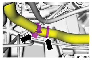
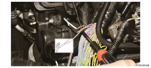
- Remove the lower radiator hose retaining clip and detach the pushpin retainer from the transmission. (Figure 1)
Figure 1
- Position the lower radiator hose aside.
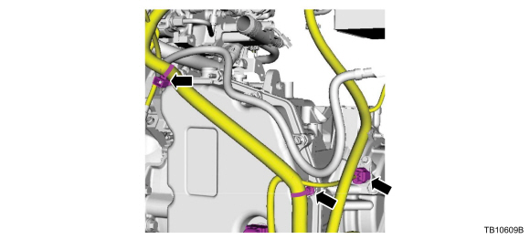
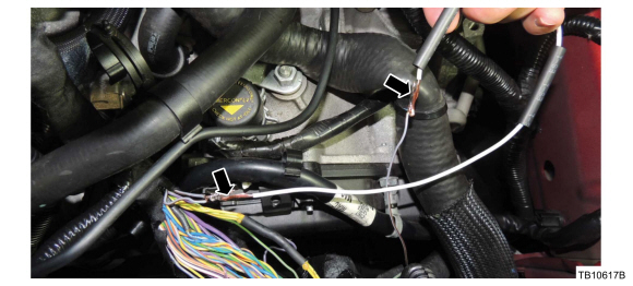
- Disconnect the two wire harness retainers and disconnect the turbine shaft speed (TSS) sensor. (Figure 2)
Figure 2
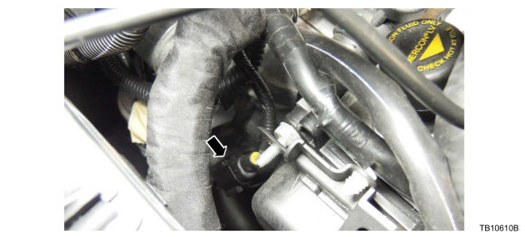
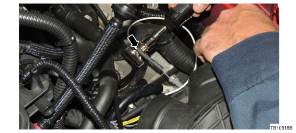
- Disconnect the starter motor wire harness electrical connector. (Figure 3)
Figure 3
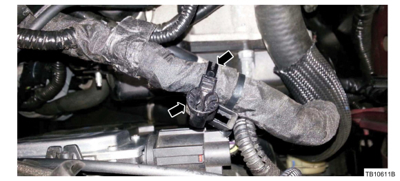
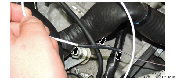
- Cut the upper wire harness retainer tie strap and remove it from the engine wire harness. (Figure 4)
Figure 4
- Remove the tie strap from the upper wire harness retainer. Save the retainer as it will be used during reassembly.
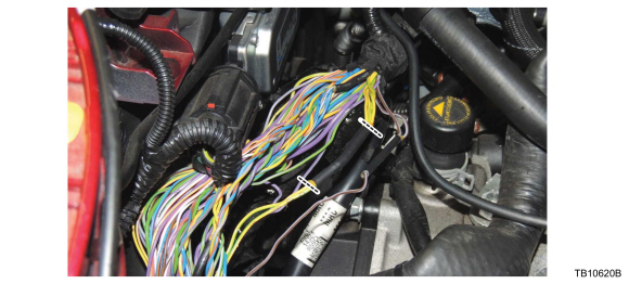
- Pull the engine wire harness upward to provide better access for the repair. Locate the section of engine wire harness that contains splice S182 and S108. (Figure 5)
Figure 5
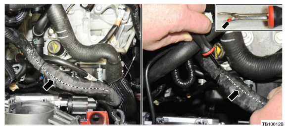
- Using a commercially available sheathing ripper such as Snap-On SGTT4A or equivalent, carefully strip the wire harness tape from the section of wire harness that contain splice S182 and S108. (Figure 5)
- Insert the ball end of the sheathing ripper into the wire harness.
- Use caution not to damage the wires or wire insulation when stripping the wire harness tape to access splice S182 and S108.
- There are several splices in the area of S182 and S108. Be sure you have located the correct splices to repair as identified below.
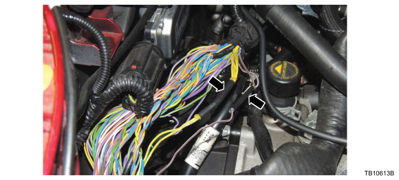
- Locate splices S182 and S108. (Figure 6)
Figure 6
-
- S182 is a one (1) wire into two (2) wire splice with gray/brown wires.
- S108 is a two (2) wire into four (4) wire splice with yellow/green wires.
- There is another splice with yellow/green wires in this area. Be sure the splice you repair with yellow/green wires is splice S108 having four (4) wires on one side and two (2) wires on the other.
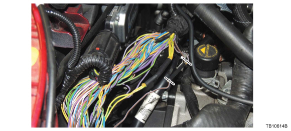
- Cut the wires on each side of splice S182 and strip off 19 mm (0.75 in.) of insulation from each of the gray/brown wires. (Figure 7)
Figure 7
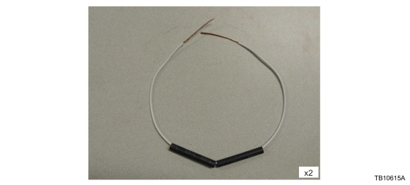
- Prepare two lengths of wire for splicing as follows. (Figure 8)
Figure 8
-
- Obtain locally two 40.6 cm (16 in.) lengths of 18 AWG wire.
- Strip 38 mm (1.5 in.) of insulation from each end of the wire.
- Position two (2) lengths of ES-1 double wall heat shrink tubing onto each wire.
- Join the two gray/brown wires on the engine side of the harness with one end of the previously prepared 40.6 cm (16 in.) length of wire. Twist 13 mm (0.5 in.) of the ends of the wires together and bend the splice wire 90 degrees to the harness wire at the end of the twisted area. Solder the wires together using lead-free electrical solder, with the heat being applied opposite of the applied solder. (Figures 9 and 10)
Figure 9
Figure 10
- Repeat this step to join the single wire end of the splice S182 gray/brown wire to the opposite end of the prepared wire.
- Position the heat shrink tubing over both ends of the splice wire. Use a suitable heat gun such as Rotunda Shielded Flameless Heat Gun with Heat Deflector, number NAIAT-R5902, that is equipped with a shrink tubing attachment, to heat the heat shrink tubing until the sealant comes out of both ends. (Figures 11 and 12)
Figure 11
Figure 12
- Cut the wires on each side of splice S108 and strip off 19 mm (0.75 in.) of insulation from each of the yellow/green wires. (Figure 13)
Figure 13
-
- There is another splice with yellow/green wires in this area. Be sure the splice you repair with yellow/green wires is splice S108 having four (4) wires on one side and two (2) wires on the other.
- Repeat Steps 13 and 14 for both ends of splice S108 yellow/green wires.
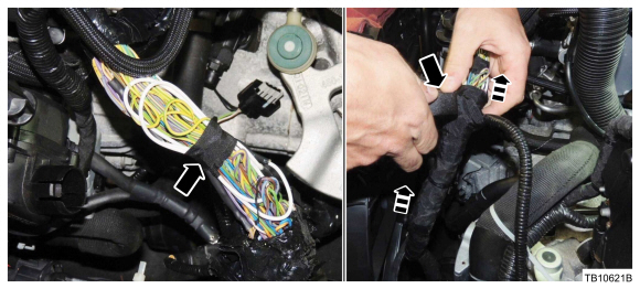
- Bundle the wires as shown and apply wire harness tape to the harness, starting from the bottom of the previously cut harness tape and working upward until all exposed wires are covered. (Figure 14)
Figure 14
- Connect the starter motor wire harness electrical connector. (Figure 3)
- Install the upper wire harness retainer that was removed during Step 7 onto the engine wire harness using a new tie strap. (Figure 4)
- Connect the two wire harness retainers and connect the TSS sensor. (Figure 2)
- Position the lower radiator hose back in place. Install the radiator hose retaining clip and attach the push-pin retainer onto the transmission. (Figure 1)
- Install the air cleaner and air cleaner outlet pipe.
- Install the engine appearance cover.
- Connect the battery ground cable.
| Obtain Part Locally |
| 2 ea. @ 40.6 cm (16 in.) 0.75 mm (18 AWG) Wire |
