| “This site contains affiliate links for which OEMDTC may be compensated” |
NHTSA ID Number: 10144920
Manufacturer Communication Number: TSB 18-2256
Summary
Some 2015-2017 Mustang vehicles may exhibit poor A/C performance. If the cause of this is found to be a refrigerant leak from the evaporator, it is recommended to replace only the evaporator as opposed to the entire climate control housing. Follow the Service Procedure steps to correct the condition.
3 Affected Products
Vehicle
Model:
Summary
This article supersedes TSB 18-2166 to update the causal part.
Issue: Some 2015-2017 Mustang vehicles may exhibit poor A/C performance. If the cause of this is found to be a refrigerant leak from the evaporator, it is recommended to replace only the evaporator as opposed to the entire climate control housing.
Action: Follow the Service Procedure steps to correct the condition.
Parts
| Description | Quantity | Part Number |
| Evaporator Core Service Kit (2.3L Engine) | 1 | FR3Z-19860-A |
| Evaporator Core Service Kit (3.7L, 5.0L, & 5.2L Engine) | 1 | FR3Z-19860-B |
| Upper Instrument Panel Cowl Bolts (4 per package) | 1 | W715969-S442 |
| Steering Shaft Bolt (4 per package) | 1 | W714878-S450 |
| Thermostatic Expansion Valve Upper O-Ring Seal | 1 | 6E5Z-19E889-D |
| Thermostatic Expansion Valve Lower O-Ring Seal | 1 | 6E5Z-19E889-E |
| Motorcraft R-134a Refrigerant | 1 | YN-19 |
| Motorcraft PAG Refrigerant Compressor Oil | 1 | YN-12-D |
| Motorcraft Orange Concentrated Antifreeze/Coolant | 1 | VC-3-B |
| Drive | Tool Name |
|---|---|
| 1/4″ | Impact |
| 1/4″ | Power Ratchet |
| 1/4″ | Ratchet |
| 1/4″ | Long Handle Ratchet |
| 1/4″ | Torque Wrench |
| 1/4″ | 6″ Extension |
| 1/4″ | 8″ Extension |
| 1/4″ | Universal Joint |
| 1/4″ | 10 mm Deep Socket |
| 1/4″ | Torx T27 |
| 1/4″ | Torx T20 |
| 1/4″ | 7 mm Socket |
| 1/4″ | 8 mm Socket |
| 3/8″ | Ratchet |
| 3/8″ | Torque Wrench |
| 3/8″ | 6″ Extension |
| 3/8″ | 10″ Extension |
| 3/8″ | 13 mm Deep Socket |
| 3/8″ | 15 mm Deep Socket |
| 3/8″ | 19 mm Deep Socket |
| 3/8″ | 13 mm Socket |
| 3/8″ | 15 mm Socket |
| 3/8″ | Hex #4 |
| 3/8″ | Torx T40 |
| 3/8″ | 13 mm Crows Foot |
| 3/8″ | 19 mm Crows Foot |
| 3/8″ | 13 mm Swivel Socket |
| Pocket Flathead Screwdriver | |
| Medium Flathead Screwdriver | |
| 19 mm Wrench | |
| 13 mm Flex Head Ratchet Wrench | |
| 10 mm Flex Head Ratchet Wrench | |
| Plastic Trim Tool | |
| Metal Trim Tool |
Service Procedure
1. Inspect the A/C system. Does the system show signs of leaks in components other than the evaporator?
(1). Yes – this article does not apply. Refer to Workshop Manual (WSM), Section 412-00.
(2). No – proceed to Step 2.
2. Remove the climate control housing. Refer to WSM, Section 412-00.
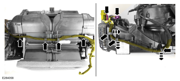
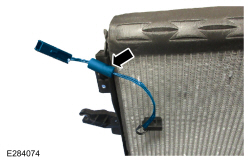
3. Disconnect and position the wiring harnesses aside. (Figures 1 – 2)
Figure 1
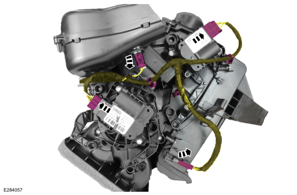
Figure 2
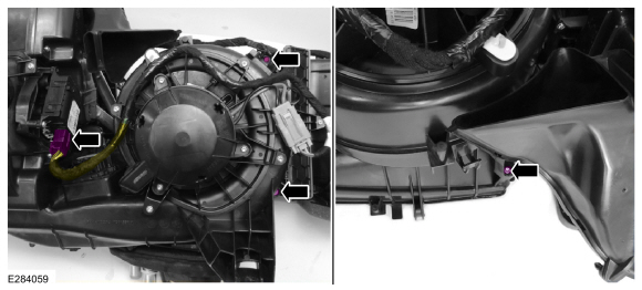
4. If equipped with dual zone climate control, disconnect the passenger blend door actuator electrical connector and remove the 3 upper plenum housing to blower motor fasteners. (Figure 3)
Figure 3
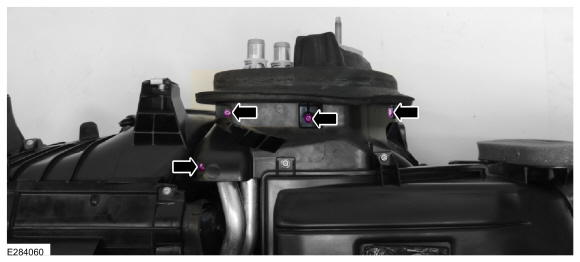
5. Remove the 4 upper plenum housing to blower motor fasteners. (Figure 4)
Figure 4
6. Position the climate control housing to bulkhead insulator aside and remove the upper plenum housing from the climate control housing. (Figure 5)
Figure 5
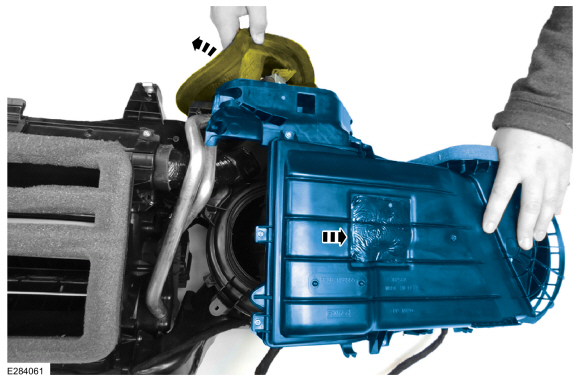
7. Remove the 2 footwell duct to climate control housing fasteners and remove the footwell duct. (Figure 6)
Figure 6
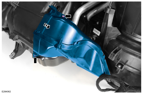
8. Remove the 2 heater core outlet pipe cover fasteners from the climate control housing and remove the cover. (Figure 7)
Figure 7
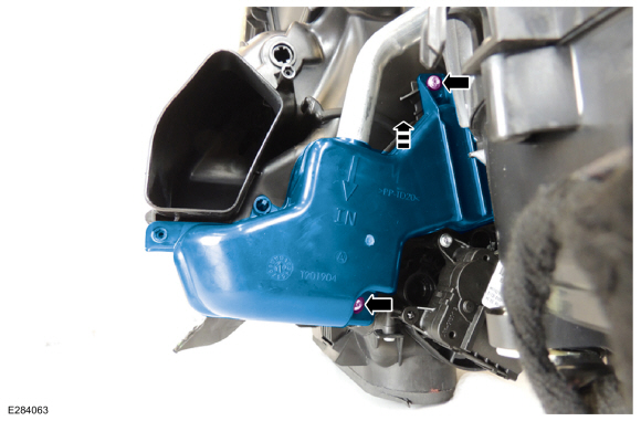
9. Remove the 2 climate control housing perimeter fasteners. (Figure 8)
Figure 8
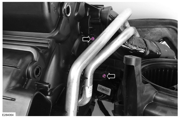
10. Remove the 3 climate control housing perimeter fasteners. (Figure 9)
Figure 9
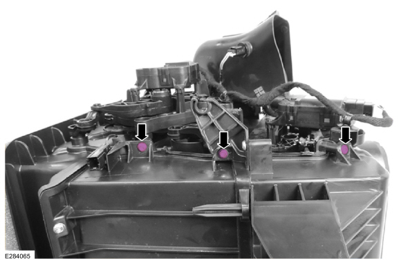
11. Remove the 4 climate control housing lower perimeter fasteners. (Figure 10)
Figure 10
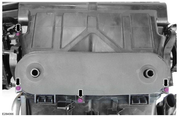
12. Remove the 4 climate control assembly perimeter fasteners. (Figure 11)
Figure 11
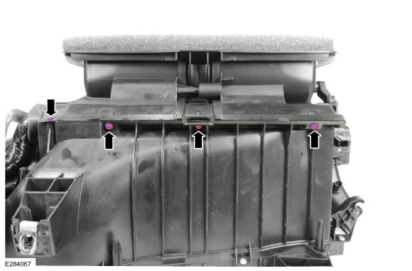
13. Position the bulkhead insulator over the thermostatic expansion valve (TXV). (Figure 12)
Figure 12
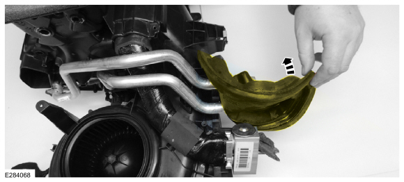
14. Remove the plenum chamber and heater core as an assembly from the climate control core housing. (Figure 13)
Figure 13
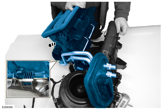
15. Remove the evaporator temperature sensor wiring seal from the slot in the climate control housing. (Figure 14)
Figure 14
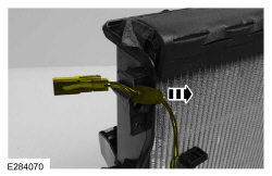
16. Remove the evaporator core from the climate control housing. (Figure 15)
Figure 15
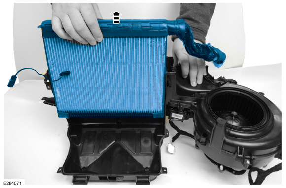
17. Install the new evaporator core. Push down on the evaporator core firmly to make sure it is fully seated in the climate control housing. (Figure 16)
Figure 16
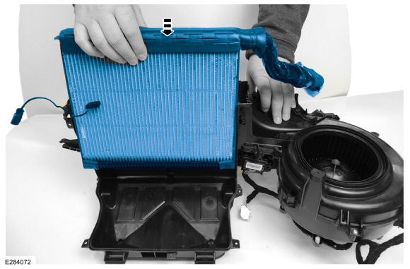
18. The new evaporator core may require a minor adjustment to the lines in order to fit properly in the climate control housing. (Figure 17)
Figure 17
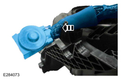
19. Install the evaporator temperature sensor wiring seal into the slot in the climate control housing. (Figure 18)
Figure 18
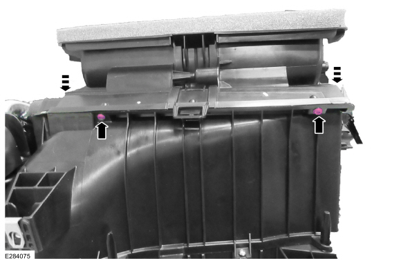
20. Assemble the two climate control housing halves.
(1). Push down on the corners of the housing, not the center tab.
(2). The housing fasteners may need to be started in order to draw the two halves together due to the new evaporator core foam being uncompressed. (Figure 19)
Figure 19
21. Install the bulkhead insulator over the TXV. (Figure 12)
22. Install the 4 climate assembly perimeter fasteners. (Figure 11)
23. Install the 4 climate control housing lower perimeter fasteners. (Figure 10)
24. Install the 3 climate control housing perimeter fasteners. (Figure 9)
25. Install the 2 climate control housing perimeter fasteners. (Figure 8)
26. Install the heater core outlet pipe cover and the 2 fasteners in the climate control housing. (Figure 7)
27. Install the footwell duct to the climate control housing and install the two fasteners. (Figure 6)
28. Install the upper plenum housing to the climate control housing and position the bulkhead insulator back on. (Figure 5)
29. Install the 4 upper plenum housing to blower motor fasteners. (Figure 4)
30. If equipped with dual zone climate control, connect the passenger blend door actuator electrical connector and install the 3 upper plenum housing to blower motor fasteners. (Figure 3)
31. Connect and position the wiring harness into the anchor points. (Figure 2)
32. Connect and position the wiring harness back together. (Figure 1)
33. Apply the supplied black putty to the outside of the climate control housing where the two case halves come together. (Figure 20)
Figure 20
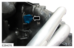
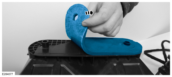
34. Remove the old climate control housing assembly foam isolator and apply the new foam isolator. (Figure 21)
Figure 21
35. Reinstall the climate control housing. Refer to WSM, Section 412-00.
(1). Prior to connecting the lines, replace the rubber O-ring gaskets between the A/C lines and evaporator core.
(2). Prior to charging the A/C system, evacuate the system for a minimum of 45 minutes using a refrigerant service unit. After 45 minutes turn off the vacuum pump and monitor the low pressure gauge for a minimum of 15 minutes to make sure no other refrigerant leaks are present. Refer to WSM, Section 412-00.
1 Associated Document
Manufacturer Communications
18-2256
21 August 2018
MC-10144920-9999.pdf 1890.812KB
 Loading...
NHTSA ID Number: 10143077
Manufacturer Communication Number: TSB18-2166
Summary
Some 2015-2017 Mustang vehicles may exhibit poor A/C performance. If the cause of this is found to be a refrigerant leak from the evaporator, it is recommended to replace only the evaporator as opposed to the entire climate control housing. Follow the Service Procedure steps to correct the condition.
1 Associated Document
Manufacturer Communications
18-2166
07 June 2018
MC-10143077-9999.pdf 1880.064KB
 Loading...
- Universal - ZeroR AC Refrigerant is a hydrocarbon that safely bonds with chemicals like R134a, R1234YF and R12. We can only advertise this product to be used in R134a systems due to EPA regulations in the USA on both R12 and R1234YF systems. EPA also prohibits mixing refrigerant types. See the description for all legal disclaimers.
- Easy - This product installs just as easily as any R134a products. Cans even have R134a threads and the majority of R134a can taps will work for these cans.
- 6oz Cans - Refrigerants are compressed gasses and are measured by weight, not by liquid volume such as water. All gasses compress differently and produce a different weight. ZeroR AC Refrigerant is low weight compared to R134a, but its performance is equal to 16oz of R134a.
- Eco Friendly – ZeroR AC Refrigerant is a 100% Natural gas unlike R134a, R1234yf and R12.
- Safe – ZeroR AC Refrigerant has a class 2.1 flammability rating just like the new R1234YF which is now used in 100% of newly manufactured vehicles. Under normal operating conditions this product presents no danger to its users when handled properly and used in systems approved for flammable refrigerants.
- Approved for use in California
- High Mileage refrigerant for vehicles over 75, 000 miles
- Contains approximately 10 oz. of R-134a and 2 oz. of additives
- Contains leak sealer to seal common A/C leaks in rubber hoses, gaskets, and O-rings
- Contains high mileage No wear additives
- This item cannot be shipped to Washington or California
- Contains approximately 1.5oz of refrigerant and 1.5oz of additives
- Repairs Metal Leaks in evaporators, condensers, compressors, accumulators and receiver dryers
- Seals Rubber Leaks in O-rings, gaskets, and hoses
- With red dye for detecting leaks too large to repair
- Reusable dispensing hose designed for compliance and to work only with R-134a cans with self-sealing valve can tops
- Replaces lost R-134a refrigerant and oil in automotive A/C system
- System safe stop leak sealer stops most common A/C leaks with hoses, gaskets and O-Rings
- Special anti-wear additives extend system life and improve performance
- Contains R-134a gas which is acceptable for use in motor vehicle A/C (MVAC) systems
- Complies with Section 612 of the EPA Clean Air Act, EPA Compliant in Self Sealing Cans
- Digital gauge with guided command
- Guided Commands eliminate the guesswork
- 24” Long Hose
- Trigger Dispenser
- Quick Connect Coupler
- Universal PAG R134a Oil Charge, 4 oz. (9145)
SEOCONTENT-START
| TECHNICAL SERVICE BULLETIN Poor Air Conditioning (A/C) Performance – Evaporator Can Now Be Serviced Separately From The Climate Control Housing |
18-2256 21 August 2018 |
This bulletin supersedes 18-2166. Reason for update: Replace Awareness/Interim Message
Warranty Status: Eligible Under Provisions Of New Vehicle Limited Warranty Coverage Warranty/ESP coverage limits/policies/prior approvals are not altered by a TSB. Warranty/ESP coverage limits are determined by the identified causal part and verified using the OASIS part coverage tool.
Labor Times
| Description | Operation No. | Time |
| 2015 Mustang Manual Transmission: Visually Inspect A/C System And Replace Evaporator Core Following The Service Procedure (Do Not Use With Any Other Labor Operations) | 182256A | 4.9 Hrs. |
| 2016-2017 Mustang Manual Transmission: Visually Inspect A/C System And Replace Evaporator Core Following The Service Procedure (Do Not Use With Any Other Labor Operations) | 182256B | 5.1 Hrs. |
| 2015 Mustang Automatic Transmission: Visually Inspect A/C System And Replace Evaporator Core Following The Service Procedure (Do Not Use With Any Other Labor Operations) | 182256C | 5.2 Hrs. |
| 2016-2017 Mustang Automatic Transmission: Visually Inspect A/C System And Replace Evaporator Core Following The Service Procedure (Do Not Use With Any Other Labor Operations) | 182256D | 5.4 Hrs. |
Repair/Claim Coding
| Causal Part: | 19860 |
| Condition Code: | D7 |
SEOCONTENT-END
Last update on 2025-05-10 / Affiliate links / Images from Amazon Product Advertising API
This product presentation was made with AAWP plugin.


