
March 27, 2017 NHTSA CAMPAIGN NUMBER: 17V209000
Engine Cylinder Head may Leak Oil
If the cylinder head cracks and leaks oil, the oil may contact a hot engine or exhaust component, increasing the risk of a fire.
NHTSA Campaign Number: 17V209
Manufacturer Ford![]() Motor Company
Motor Company
Components ENGINE AND ENGINE COOLING
Potential Number of Units Affected 208,584
Summary
Ford![]() Motor Company (Ford
Motor Company (Ford![]() ) is recalling certain 2014 Escape, 2014-2015 Fiesta ST, 2013-2014 Fusion and 2013-2015 Transit Connect vehicles equipped with 1.6L GTDI engines. If the vehicle is started and driven with an insufficient level of coolant within the engine cooling system, the engine cylinder head may overheat, crack and leak oil.
) is recalling certain 2014 Escape, 2014-2015 Fiesta ST, 2013-2014 Fusion and 2013-2015 Transit Connect vehicles equipped with 1.6L GTDI engines. If the vehicle is started and driven with an insufficient level of coolant within the engine cooling system, the engine cylinder head may overheat, crack and leak oil.
Remedy
Ford![]() will notify owners, and dealers will install a coolant level sensor and the supporting hardware and software, free of charge. Interim notices informing owners of the safety risk were mailed April 21, 2017. The recall began on January 5, 2018. Owners may contact Ford
will notify owners, and dealers will install a coolant level sensor and the supporting hardware and software, free of charge. Interim notices informing owners of the safety risk were mailed April 21, 2017. The recall began on January 5, 2018. Owners may contact Ford![]() customer service at 1-866-436-7332. Ford
customer service at 1-866-436-7332. Ford![]() ’s number for this recall is 17S09.
’s number for this recall is 17S09.
Notes
Owners may also contact the National Highway Traffic Safety Administration Vehicle Safety Hotline at 1-888-327-4236 (TTY 1-800-424-9153), or go to www.safercar.gov.
Check if your Vehicle has a Recall
June 7, 2018
Safety Recall 17S09 – Supplement #3
Certain 2013-2014 Fusion, 2013-2015 Transit Connect, 2014 Escape, and 2014-2015
Fiesta ST Vehicles Equipped with a 1.6L EcoBoost Engine
Coolant Level Sensor System Installation
REASON FOR THIS SUPPLEMENT
- Service Action Update: Parts are now available to complete this safety recall on Fiesta ST vehicles.
AFFECTED VEHICLES
| Vehicle | Model Year | Assembly Plant | Build Dates |
| Escape | 2014 | Louisville | February 12, 2013 through September 2, 2014 |
| Fiesta ST | 2014-2015 | Cuautitlan | January 22, 2013 through May 27, 2014 |
| Fusion | 2013-2014 | Hermosillo | February 15, 2012 through June 6, 2014 |
| Transit Connect | 2013-2015 | Valencia | June 13, 2013 through December 14, 2014 |
REASON FOR THIS SAFETY RECALL
In the affected vehicles, localized overheating of the engine cylinder head may cause the cylinder head to crack, causing a pressurized oil leak that may result in a fire in the engine compartment.
SERVICE ACTION
All Affected Vehicles:
Parts ordering information and repair instructions to repair all affected vehicles are now available.
Dealers are to perform repairs following the technical information that include enhancements to the engine cooling and control systems. This service must be performed on all affected vehicles at no charge to the vehicle owner.
Important! A small number of Escape vehicles will require unique PCM programming instructions. A small number of 2015 MY Transit Connect vehicles will require an additional cylinder head inspection. Please refer to Attachment VI prior to carrying out any repairs on Escape or 2015 MY Transit Connect vehicles, as certain VINs will require a contact to the Special Service Support Center (SSSC) for additional repair instructions.
Prepare your dealership to efficiently perform the repair:
- Review the repair instructions, which include 11 modular sub-procedures as identified in the Escape and Transit Connect technical information (Attachment IV).
- Watch the instructional videos and become familiar with the repair instructions and parts.
OWNER NOTIFICATION MAILING SCHEDULE
Owners of record were notified of this safety recall via first-class mail the week of April 24, 2017.
Owners of Escape vehicles were notified of the final repair the week of January 1, 2018.
Owners of Fusion and Transit Connect vehicles were notified of the final repair the week of January 29, 2018.
Owners of Fiesta ST vehicles will be notified of the final repair the week of June 18, 2018.
Dealers should repair any affected vehicles that arrive at their dealerships, whether or not the customer has received a letter.
PLEASE NOTE:
Federal law requires dealers to complete this recall service before a new vehicle is delivered to the buyer or lessee. Violation of this requirement by a dealer could result in a civil penalty of up to $21,000 per vehicle. Correct all vehicles in your new vehicle inventory before delivery.
SOLD VEHICLES
All Affected Vehicles:
- Owners of affected vehicles will be directed to dealers for repairs.
- Immediately contact any of your affected customers whose vehicles are not on your VIN list but are identified in OASIS. Give the customer a copy of the Owner Notification Letter (when available) and schedule a service date.
- Correct other affected vehicles identified in OASIS which are brought to your dealership.
- Dealers are to prioritize repairs of customer vehicles over repairs of new and used vehicle inventory.
STOCK VEHICLES
All Affected Vehicles:
Use OASIS to identify any affected vehicles in your used vehicle inventory.
DEALER-OPERATED RENTAL VEHICLES
The Fixing America’s Surface Transportation (FAST) Act law effective June 2016 prohibits a rental company from selling, renting or leasing vehicles subject to a safety or compliance recall. Please consult your legal counsel for legal advice.
TITLE BRANDED / SALVAGED VEHICLES
Affected title branded and salvaged vehicles are eligible for this recall.
OWNER REFUNDS
- This safety recall must still be performed, even if the owner has paid for a previous repair. Claiming a refund will not close the recall on the vehicle.
- Ford
 Motor Company is offering a refund for owner-paid repairs covered by this recall if the repair was performed prior to the date indicated in the reimbursement plan, which is posted with this bulletin. Owners are directed to seek reimbursement through authorized dealers or, at their option, directly through Ford Motor Company at P.O. Box 6251, Dearborn, MI 481216251.
 - Dealers are also pre-approved to refund owner-paid emergency repairs that were performed away from an authorized servicing dealer after the end date specified in the reimbursement plan. Non-covered repairs, or those judged by Ford to be excessive, will not be reimbursed.
- Refunds will only be provided for the cost associated with an engine coolant leak or overheat.
RENTAL VEHICLES
Dealers are pre-approved for up to 1 day for a rental vehicle. Follow Extended Service Plan (ESP) guidelines for dollar amounts. Rentals will only be reimbursed for the day(s) the vehicle is at the dealership for part replacement. Prior approval for more than 1 rental day is required from the SSSC via the SSSC Web Contact Site.
PARTS REQUIREMENTS
Escape Vehicles Built on or before August 23, 2014:
Note: These vehicles use a 6-Pin Wiring Harness
| Description | Order Quantity | Claim Quantity | Part Number |
| Coolant Level Sensor Kit | 1 | 1 | GV6Z-9P449-E |
| Degas Bottle and Cap Kit | 1 | 1 | GV6Z-9P449-A |
| 6-Pin EPAS Connector Coolant Stand-pipe Wire Harness | 1 | 1 | EV4Z-14A411-F |
| Motorcraft Orange Antifreeze / Coolant Prediluted (US) | 1 Gallon | 1 Gallon | VC-3DIL-B

Ford Genuine Anti Freeze, VC-13DL-G
Last update on 2026-06-18 / Affiliate links / Images from Amazon Product Advertising API |
| Motorcraft Orange Antifreeze / Coolant Prediluted (Canada) | CVC-3DIL-B |
Escape Vehicles Built on or after August 24, 2014 and all Transit Connect Vehicles: Note: These vehicles use a 3-Pin Wiring Harness.
| Description | Order Quantity | Claim Quantity | Part Number |
| Coolant Level Sensor Kit | 1 | 1 | GV6Z-9P449-E |
| Degas Bottle and Cap Kit | 1 | 1 | GV6Z-9P449-A |
| 3-Pin EPAS Connector Coolant
Stand-pipe Wire Harness |
1 | 1 | EV4Z-14A411-H |
| Motorcraft Orange Antifreeze / Coolant Prediluted (US) | 1 Gallon | 1 Gallon | VC-3DIL-B
Ford Genuine Anti Freeze, VC-13DL-G
Last update on 2026-06-18 / Affiliate links / Images from Amazon Product Advertising API |
| Motorcraft Orange Antifreeze / Coolant Prediluted (Canada) | CVC-3DIL-B |
Fusion Vehicles:
| Description | Order Quantity | Claim Quantity | Part Number |
| Coolant Level Sensor Kit | 1 | 1 | DG9Z-9P449-A |
| Thermostat Kit | 1 | 1 | GV6Z-9P449-C |
| Coolant Stand-pipe Wire Harness | 1 | 1 | DG9Z-14A411-J |
| Motorcraft Orange Antifreeze / Coolant Prediluted (US) | 1 Gallon | 1 Gallon | VC-3DIL-B
Ford Genuine Anti Freeze, VC-13DL-G
Last update on 2026-06-18 / Affiliate links / Images from Amazon Product Advertising API |
| Motorcraft Orange Antifreeze / Coolant Prediluted (Canada) | CVC-3DIL-B |
| Description | Order Quantity | Claim Quantity | Part Number |
| PCM Connector Back Shell Kit – Fusion Vehicles with Manual Transmission Only | 1 | 1 | DG9Z-14A666-L |
PARTS REQUIREMENTS Fiesta ST Vehicles:
| Description | Order Quantity | Claim Quantity | Part Number |
| Coolant Level Sensor Kit | 1 | 1 | H1BZ-9P449-F |
| Thermostat Kit | 1 | 1 | GV6Z-9P449-C |
| Coolant Stand-pipe Wire Harness | 1 | 1 | C1BZ-14A411-L |
| Motorcraft Orange Antifreeze / Coolant Prediluted (US) | Up to 1 Gallon (only as required) | Up to 1 Gallon (only as required) | VC-3DIL-B
Ford Genuine Anti Freeze, VC-13DL-G
Last update on 2026-06-18 / Affiliate links / Images from Amazon Product Advertising API |
| Motorcraft Orange Antifreeze / Coolant Prediluted (Canada) | CVC-3DIL-B |
||
| Lead-free solder (SAC305 or equivalent) | Claim as Misc. Expense: OTHER | Obtain Locally | |
CERTAIN 2013-2014 FUSION, 2013-2015 TRANSIT CONNECT, 2014 ESCAPE, AND 2014-2015 FIESTA ST VEHICLES EQUIPPED WITH A 1.6L ECOBOOST ENGINE — COOLANT LEVEL SENSOR SYSTEM INSTALLATION2014-2015 FIESTA ST TECHNICAL INFORMATION
OVERVIEW
In the affected vehicles, localized overheating of the engine cylinder head may cause the cylinder head to crack, causing a pressurized oil leak that may result in a fire in the engine compartment.
Service parts and repair procedures are now available to address this safety recall. Dealers are to perform repairs following the technical information in this document that include enhancements to the engine cooling and control systems. This service must be performed on all affected vehicles at no charge to the vehicle owner.
Due to the complexity of this repair, the following considerations have been made to help the repair procedure go as smoothly as possible:
- Repair procedures have been divided alphabetically into multiple separate procedures.
- Parts have been packaged into kits.
- Each procedure includes:
- Overview
- List and photo of the parts required
- List of unique tools needed
- Service tips to help complete the repair
NOTE: Please read this procedure in its entirety, prior to performing repairs. Additionally, instructional videos have been developed to assist with the repair. Please refer to Attachment VII: Instructional Video Links to view the videos.
Recommended Tools:
| General Tools | |
|---|---|
| 1/4” Drive Ratchet (Power and Hand Tool) | Cut-Off Wheel |
| 1/4″ Drive 7, 8, and 10 mm Shallow Sockets | Terminal De-Pin Tools |
| 1/4″ Drive 10 mm, 12 mm Deep Sockets | Soldering Iron |
| 1/4″ Drive 8 mm Swivel Socket | Heat Gun |
| 1/4″ Drive E8 Inverted Torx Socket | Wire Strippers |
| 1/4″ Drive 6 in (152 mm) and 12 in (304 mm) Extensions | Tape Measure/ Flex Ruler |
| 3/8″ Drive Ratchet (Power and Hand Tool) | |
| 3/8″ Drive 13 mm, and 15 mm Deep Impact Socket | General Equipment |
| 3/8″ Drive 15 mm Shallow Impact Socket | Floor Jack |
| 3/8″ Drive 15 mm Swivel Impact Socket | Wood Block |
| 3/8″ Drive 6 in (152 mm) Extension | Coolant Pressure Tester |
| 1/2″ Drive Ratchet Power Tool and Hand Tool | Drain Pan |
| 1/4″ and 1/2″ Drive Impact Swivel | Battery Charger |
| 1/2″ Drive 15mm Shallow Impact Socket | Tape/Electrical Tape |
| 1/2″ Drive 6″ (152 mm) Impact Extension | Extension Cord |
| 1/2″ Drive Torque Wrench | |
| 1/4″ And 3/8″ Drive Torque Wrench | Special Tools |
| 13 mm and 15 mm Ratchet Wrench | Hydrometer/Refractometer |
| 17 mm Wrench 15 in (381 mm) | Vacuum Tester/Re-filler |
| Channel Lock Pliers | IDS and VCM II |
| Trim Tool 7 in (177 mm) and 12 in (304 mm) | |
| Inspection Mirror | |
| Two Jaw Puller | |
| Phillips Screwdriver 20 in (508 mm) | |
| Paint Stick/Pen | |
| Scissors | |
| Cable Operated Hose Pliers | |
| 5 in (127 mm) and 12 in ( 304 mm) Pick Tool | |
| Pocket Screwdriver | |
| Side Cutters | |
| Needle Nose Pliers 9 in (228 mm) | |
| Hose Hook Tool | |
SERVICE PROCEDURE
Procedure A – Initial Disassembly and Preparation for Inspection
OVERVIEW: This procedure details the components to be removed to enable initial vehicle inspection.
PARTS / SUPPLIES REQUIRED: None
UNIQUE TOOL REQUIREMENTS: None
SERVICE TIPS: Please note the following:
- The Inspection / Check Sheet (Attachment V) must be printed and started during “Procedure A”.
- Cover the turbocharger inlet opening to prevent dropping any parts or debris into the turbocharger while the turbocharger inlet pipe is off.
- Print a copy of the Inspection / Check Sheet (Attachment V), to record vehicle information and inspection/repair information for the vehicle. The Inspection / Check Sheet is to be attached/filed with the recall repair order following completion, it does not need to be provided to Ford at this time.
- Fill out top of Inspection / Check Sheet including:
- VIN
- Technician ID
- Repair Order Number
- Repair Date
- Vehicle Mileage
- Vehicle Build Date
- Open Recalls
- Using OASIS, document vehicle build date on the Inspection / Check Sheet.
- With the vehicle in NEUTRAL, position it on a hoist. Please follow the Workshop Manual (WSM) procedures in Section 100-02.
- Using IDS/scan tool, retrieve and record DTCs on the Inspection / Check Sheet.
- Any DTCs recorded will be used later in this procedure.
- Remove the cowl panel grille and cowl panel. Please follow the WSM procedures in Section 501-02.
NOTICE: When working with liquid or vapor tube connectors, make sure to use compressed air to remove any foreign material from the connector retaining clip area before separating from the tube or damage to the tube or connector retaining clip can occur. Apply clean engine oil to the end of the tube before inserting the tube into the connector.
NOTICE: Whenever turbocharger air intake system components are removed, always cover open ports to protect from debris. It is important that no foreign material enter the system. The turbocharger compressor vanes are susceptible to damage from even small particles. All components should be inspected and cleaned, if necessary, prior to installation or reassembly.
- Remove the air cleaner outlet pipe. Please follow the WSM procedures in Section 303-12C.
- Remove the generator. Please follow the WSM procedures in Section 412-02.
- Remove the turbocharger air inlet pipe. See Figure A1.
- Disconnect the crankcase ventilation tube quick release coupling. Please follow the WSM procedures in Section 310-00C.
- Remove the turbocharger air inlet pipe retaining nut, the ball stud.
- Loosen the turbocharger air inlet pipe clamp and remove the turbocharger air inlet pipe.
 FIGURE A1
- Detach the three wire harness retainers, disconnect the crankshaft position sensor, turbocharger wastegate regulating valve solenoid, and turbocharger bypass valve electrical connectors. See Figure A2.
 FIGURE A2
Procedure B – Inspection / Check Sheet CompletionOVERVIEW: The Inspection must be completed and documented on the Inspection / Check Sheet. The inspection will check for obvious concerns that require correction with additional focus on cooling system concerns such as:
- Internal coolant leaks
- External coolant leaks
- Any DTC(s) that could indicate a recent engine overheat event or internal engine damage that may have resulted from a previous cooling system concern.
PARTS / SUPPLIES REQUIRED: None
UNIQUE TOOL REQUIREMENTS: Rotunda Cooling System Pressure Tester (STN12270) and adapter (Snap-On TA52, AST ASSFZ-47, Redline RDL95-0750 or equivalent).
SERVICE TIPS: Use standard Workshop Manual and PC/ED Diagnostics, if necessary, to diagnose any cooling system or misfire DTC(s) retrieved and for any coolant loss concerns.
NOTE: Perform an underhood visual inspection for any obvious coolant, oil, transmission, or fuel leaks.
NOTE: If any concerns are identified repair as related damage before proceeding. If the coolant pressure test identifies concerns with the degas bottle, turbocharger return tube, upper section of the degas bottle return hose, or quick connect T-fitting at the coolant shutoff solenoid valve; note the condition. These items will be replaced as part of this recall. Refer to Dealer Bulletin Attachment I, Related Damage, for related damage claiming.
Vehicle Inspection
- Visually inspect the coolant level in the degas bottle.
- If the coolant level is visible in the degas bottle, proceed to Step 2.
- If the coolant level is not visible in the degas bottle, add coolant as necessary, and proceed to Step 2.
NOTE: Any gross loss of coolant must be identified and repaired prior to proceeding.
- Remove the degas bottle cap.
- Install a coolant pressure tester with adapter onto the degas bottle. Pressurize to 138 kPa (20 psi). Once stabilized, pressure should hold at 138 kPa (20 psi) for a minimum of 2 minutes.
- If cooling system pressure does not hold for a minimum of 2 minutes, the source of pressure loss must be identified and repaired as necessary before proceeding.
- Visually check for coolant leaks with the system under pressure.
- Check the engine oil level to ensure it is within normal range, note if it is overfilled. Visually check for engine oil leaks at the rear surface of the cylinder head, above exhaust manifold, that may be the result of a crack in the cylinder head. See Figure B1.
- If an oil leak is detected at the rear surface of the cylinder head, replace the complete cylinder head assembly before proceeding.
NOTE: The turbocharger coolant tubes and exhaust manifold heat shield are removed for clarity.
 FIGURE B1
- DTCs – Note and identify the cause of the following DTCs before proceeding:
- If additional DTCs are present, diagnose and repair as required.
NOTE: Diagnosis for any of the following DTCs may require reinstallation of the air intake components and battery. Perform diagnosis and repairs as necessary.
Cooling System DTCs
| P0217 | Engine Coolant Over Temperature Condition |
| P0218 | Transmission Fluid Over Temperature Condition |
| P0219 | Engine Over Speed Condition |
| P1299 | Cylinder Head Over Temperature Protection Active |
Engine Misfire DTCs
| P0300 | Random Misfire Detected |
| P030x | Cylinder X Misfire Detected |
| P0313 | Misfire Detected With Low Fuel |
| P0316 | Misfire Detected On Startup (First 1000 Revolutions) |
- Note any issues and/or repairs made on the Inspection / Check Sheet.
Procedure C – Not Required for Fiesta ST Vehicles
Procedure D – Coolant Stand-pipe Wire Harness Installation
OVERVIEW: The coolant stand-pipe wire harness is installed in this procedure. This is necessary to complete the connections which are a part of the CAN Network. The CAN Network must be complete to allow module programming.
PARTS / SUPPLIES REQUIRED:

| A | Coolant Stand-pipe Wire Harness |
| B | Connector Shell (which will receive the male pins) |
| C | Connector Shell with female pins and Wire Harness |
| D | Tie-Straps |
| E | Heat Shrink Tubing x5 |
UNIQUE TOOL REQUIREMENTS: Soldering Iron, Heat Gun
SERVICE TIPS: None
- Remove the battery. Please follow the procedures in WSM Section 414-01.
- Position the LH front door weatherstrip aside, remove the push-pins, the scuff plate and the lower cowl trim panel. See Figure D1.
 FIGURE D1
- Loosen the bolt and disconnect connector C211. Remove the two retainers and position aside
connector C211. See Figure D2.
 FIGURE D2
NOTICE: Use a blunt tip Phillips screwdriver and do not push far inward through the bulkhead insulation. Use caution to prevent damage to the wire harness on the interior side of the vehicle near the parking brake cable/bulkhead plug. See Figures D3 and D4.
- Remove the bulkhead plug located on the driver’s side of the vehicle near the hood release cable, by inserting a Phillips screw driver and push inward to dis-engage the plug. See Figure D3.
 FIGURE D3
- Continue pushing inward on the Phillips screw driver to push through the bulkhead insulation and then remove the Phillips screw driver from the hole. See Figure D4.
 FIGURE D4
- Widen the hole in the insulation using a utility knife. Use caution not to damage the surrounding wire harnesses or hood release cable. See Figure D5.
NOTE: Stand-pipe wire harness shown installed for reference.
 FIGURE D5
- Using the Coroplast tape provided in the parts kit secure the stand-pipe wire harness pins and wires to a length of mechanics wire. See Figure D6.
 FIGURE D6
- Fish the stand-pipe wire harness through the bulkhead, pull the grommet through the bulkhead and then back out slightly to seat the slot in the grommet in the bulkhead sheet metal. See Figure D7.
 FIGURE D7
- Route the coolant stand-pipe wiring harness along the engine compartment wire harness, from the left-hand side of the engine compartment to the degas bottle area. Use tie-straps to secure the wiring harness to the engine compartment wiring harness. See Figure D8
 FIGURE D8
NOTE: A completed view of the modified vehicle wiring is provide for reference during this procedure. Review the steps and diagrams below prior to proceeding. See Figure D9.
 FIGURE D9
NOTE: A wire diagram of the modified vehicle wiring is provide for reference during this procedure. Review the steps and diagrams below prior to proceeding. See Figure D10.
 FIGURE D10
- Remove the two bolts and position the OBDII/Data Link Connector (DLC) aside.
- From the DLC connector, remove the following wires/pins from the connector shell (see Figure D11):
- Pin 4 – Black/Gray wire
- Pin 6 – White/Blue wire
- Pin 14 – White wire
 FIGURE D11
- Cut the metal terminal ends off of the three wires removed from the OBDII/DLC connector shell. The wires will be spliced later in this procedure. See Figure D12.
 FIGURE D12
NOTICE: Review the wire diagrams and splicing locations shown in Figure 10, prior to proceeding. Follow the recommended splicing techniques found in the wire diagrams when splicing wires. Use only ES-1 dual wall heat shrink tubing on each wire to be spliced.
- Insert the smaller terminal wires from the new stand-pipe wire harness into the OBDII/DLC connector as follows (See Figures D9 and D13):
- Pin 4 – new Black/Gray wire
- Pin 6 – new White/Blue wire
- Pin 14 – new White wire
 FIGURE D13
- Insert the larger male terminal wires from the new stand-pipe wire harness into the new connector shell as follows (See Figures D9 and D13):
- Pin 1 – new Double Blue/Gray wire
- Pin 2 – new Double White/Blue wire
- Pin 3 – new Double White wire
- Pin 4 – new Double Black/Gray wire
- Locate the C210 Pin 13 Blue/Gray wire and cut the wire so that at least 4 in (101.6 mm) of wire remains on the connector side. See Figure D9, D10 and D16.
- Remove wire harness tape if required.
- From the Blue/Gray wire on the connector shell with female pins and wire harness, cut 20 in (508 mm) of the wire to create a jumper wire to be spliced in the following steps. See Figure D14.
 FIGURE D14
- Prepare the Blue/Gray jumper wire for splicing as follows. See Figure D15.
- Remove 1 in (25.4 mm) of insulation from each end of the wire.
- Position two (2) lengths of ES-1 dual wall heat shrink tubing onto the wire.
 FIGURE D15
- Splice the three Blue/Gray Wires together on the body side of the harness:
- C210 Pin 13 body side
- 20 in (508 mm) Jumper Wire
- Blue/Gray wire from connector shell with female pins and wire harness
Twist 13 mm (0.5 in.) of the ends of the wires together and bend the splice wire 90 degrees to the harness wire at the end of the twisted area.
Solder the wires together using lead free electrical solder, with the heat being applied opposite of the applied solder. See Figure D16.
 FIGURE D16
- Splice the other end of the 20 in (508 mm) Jumper Wire to C210 Pin 13 connector side Blue/Gray wire, using the same splicing instructions as the previous step. See Figure D17.
 FIGURE D17
- Position the heat shrink tubing over both ends of the splice wires. Use a suitable heat gun such as Rotunda Shielded Flameless Heat Gun with Heat Deflector, number NAIAT-R5902, that is equipped with a shrink tubing attachment, to heat the heat shrink tubing until the sealant comes out of both ends. See Figure D18.
- Loop the Blue Gray jumper wire and secure it with Coroplast Tape along the main harness. See Figure D18.
 FIGURE D18
- Splice the three wires removed from the OBDII/DLC connector shell earlier in this procedure to the new connector shell with female pins and wire harness. Position heat shrink tubing onto the remaining wires to be spliced. Make the remaining splices following the splicing technique done for the Blue/Gray Jumper wire previously.
NOTE: Refer to Figure D10 for wire schematic.
- Pin 2 – new Black/Gray wire to the previously removed OBDII/DLC connector Black/Gray wire.
- Previously OBDII/DLC connector Pin 4.
- Pin 3 – new White/Blue wire to the previously removed OBDII/DLC connector White/Blue wire.
- Previously OBDII/DLC connector Pin 6.
- Pin 4 – new White wire to the previously removed OBDII/DLC connector White wire.
- Previously OBDII/DLC connector Pin 14.
- Position the heat shrink tubing over both ends of the three spliced wires. Use a suitable heat gun such as Rotunda Shielded Flameless Heat Gun with Heat Deflector, number NAIAT-R5902, that is equipped with a shrink tubing attachment, to heat the heat shrink tubing until the sealant comes out of both ends.
- Position connector C211 back onto the retaining studs and install the two retainers. See Figure D2.
- Connect connector C211.
- Connect the male and female ends of the new connector shells together. See Figure D9.
- Position the OBDII/Data Link Connector (DLC) back in its original position and install the two bolts.
- Bundle the connector C210 harness wires and the new C210 Pin 13 spliced wire and wrap the harness with Coroplast tape.
- Secure the new wires along the existing vehicle connector C211 wire harness with tie straps.
- Install the scuff plate and the lower cowl trim panel. Install the push pins. See Figure D1.
- Position the LH front door weatherstrip back. See Figure D1.
Procedure E – Instrument Panel Cluster (IPC) Reprogramming
(Not Required for Fiesta ST Vehicles)
Procedure F – Turbocharger Wire Harness Taping
OVERVIEW: This procedure wraps the turbocharger wire harness with Coroplast tape to prevent the entry/buildup of fluids and debris in the convolute which could ignite from an ignition source.
PARTS / SUPPLIES REQUIRED:

| A | Coroplast Tape |
| B | Wire Harness Retainer w/Tie-Strap |
UNIQUE TOOL REQUIREMENTS: None
SERVICE TIPS: Tips for wrapping the harness are included in the procedure.
NOTE: Figure F1 is for reference only the harness retainers were previously disconnected in Procedure A.
FIGURE F1
- Route the turbocharger wire harness to the top of the engine compartment. See Figure F2.
- If broken, replace the wire harness retainer with the new one supplied in the vehicle parts kit. See Figures F1 and F2.
- Mark the wire harness retainer location before removal.
- Wrap the turbocharger wire harness convolute with the Coroplast tape provided in the service kit. See Figure F2.
- Start and finish each length of tape applied with three (3) initial and three (3) finishing wraps.
- Apply each wrap of tape with a 50% overwrap.
- First, wrap the takeout for the crankshaft position sensor. Begin the wrap at the connector and end this portion of wrapping by going around the main harness at the takeout. See Figure F2, (A).
- Wrap the turbocharger harness starting at the side of the harness closest to the engine. Proceed down the remaining length of harness to the turbocharger wastegate regulating valve solenoid connector and turbocharger bypass valve electrical connectors. See Figure F2, (B).
 FIGURE F2
- Route the wire harness back down to the crankshaft position sensor, turbocharger wastegate regulating valve solenoid, and turbocharger bypass valve. See Figure F1.
- Connect the crankshaft position sensor, turbocharger wastegate regulating valve solenoid, and turbocharger bypass valve electrical connectors. Attach the wire harness retainers to the engine. See Figure F1.
Procedure G – Thermostat Replacement
OVERVIEW: An updated 82° C (179.6° F) thermostat will be installed to improve cooling system performance
PARTS / SUPPLIES REQUIRED:

| A | Thermostat |
| B | Thermostat housing to cylinder block O-rings (2 ea.) |
| C | Thermostat Housing to coolant valve O-Ring (1 ea.) |
UNIQUE TOOL REQUIREMENTS: None
SERVICE TIPS: Make sure the air bleed hole in the thermostat is in the “UP” position when installed to allow any air trapped in the system to pass.
- Remove the thermostat housing. Please follow the WSM procedures in 303-03.
- Discard the thermostat housing gaskets.
- Use a 13 mm (1/2 in) deep well socket to press downward on the thermostat retaining clip and rotate to remove it from the thermostat housing. Remove the thermostat spring. See Figure H2.
- Note the position of the thermostat retaining clip and thermostat prior to removing. See Figures G1 and G2.
 FIGURE G1
- Remove and discard the thermostat. See Figure G2.
- Position the new thermostat into the housing with the air bleed hole positioned upward. Use a 13 mm (1/2 in) deep well socket to install the thermostat spring and clip. The retaining clip must be in the same orientation that it was in prior to removal. See Figures G2 and G3.
 FIGURE G2
NOTICE: Do not use pliers or other tools to install the thermostat.
NOTE: The thermostat retaining clip must be installed in the position as shown. See Figure G3.
 FIGURE G3
- Install the new thermostat housing gaskets and install the thermostat housing. Please follow the WSM
procedures in 303-03.- Do not re-connect the degas bottle to thermostat housing coolant hose at this time.
- Do not re-install the generator at this time.
- Do not refill the engine coolant at this time.
Procedure H – Engine Coolant Bypass Valve Replacement
OVERVIEW: The engine coolant bypass valve is being replaced in this procedure.
PARTS / SUPPLIES REQUIRED:

| A | Engine Coolant Bypass Valve |
| B | Hose Clamp |
UNIQUE TOOL REQUIREMENTS: None
SERVICE TIPS: None
- Position the resonator assembly aside. See Figure H1.
 FIGURE H1
- Remove and discard the engine coolant bypass valve. See Figure H2.
- Disconnect the electrical connector.
- Release the clamp and disconnect the coolant hose. Discard the clamp.
- Remove the bolts and the coolant bypass solenoid valve.
- Torque: 89 lb.in (10 Nm)
 FIGURE H2
- Install a new engine coolant bypass valve and O-ring seal by reversing the removal procedure.
Procedure I – Coolant Hose Replacement
OVERVIEW: In this procedure, the coolant hose that runs between the degas bottle and thermostat quick connect T-fitting is replaced with an updated hose that allows for connection to the turbocharger coolant return line and the new coolant stand-pipe. The engine degas tube is also being replaced with an updated assembly that allows for connection to the radiator degas hose and degas bottle.
PARTS / SUPPLIES REQUIRED:

| A | Coolant Degas Bottle to Thermostat Housing Hose |
| B | Engine Degas Tube |
UNIQUE TOOL REQUIREMENTS: None
SERVICE TIPS: None
 FIGURE I1A
 FIGURE I1B
- Remove the nut and position the A/C compressor inlet line aside. See Figure I2.
 FIGURE I2
- Remove and discard the degas bottle and cap. See Figure I3.
 FIGURE I3
- Remove and discard the turbocharger coolant return hose. See Figure I4.
 FIGURE I4
- Detach the retainers, remove and discard the engine degas tube assembly. See Figure I5.
 FIGURE I5
- Disconnect the degas bottle hose from the engine oil cooler assembly. See Figure I6.
 FIGURE I6
- Detach the retainer, then remove and discard the degas hose assembly. See Figure I7.
 FIGURE I7
- Install the generator. Please follow the WSM procedures in Section 412-02.
- Do not re-install the headlamps, connect the battery or install the engine cover at this time.
NOTE: Lubricating the new coolant hoses with coolant will aid in easier installation.
NOTE: Ensure the inside of the hose fittings are free from dirt and debris.
- Install the new degas bottle hose and attach the retaining clip. Route the lower portion of the hose to the thermostat housing and oil cooler. Route the turbocharger coolant return hose upward to the top of the engine. See Figure I8.
 FIGURE I8
- Connect the thermostat quick connect fitting to the thermostat housing. See Figure I9.
 FIGURE I9
- Connect the new turbocharger coolant return hose. See Figure I10.
 FIGURE I10
- Install the new engine degas tube assembly and connect to the back of the engine. Attach the retaining clips. See Figure I11.
 FIGURE I11
- Connect the new degas bottle hose to the engine oil cooler assembly. See Figure I12.
FIGURE I12
Procedure J – Coolant Stand-pipe, Degas Bottle and Cap Installation
OVERVIEW: The coolant stand-pipe provides coolant level information to the PCM and IPC via the CAN network, this prevents overheat issues due to low coolant level by informing the driver when the coolant level is low. The coolant stand-pipe and bracket is installed using the engine mount rear fixing bolt. On installation, the wiring harness is routed across the engine bay wiring loom and the related coolant hoses are attached.
PARTS / SUPPLIES REQUIRED:

| A | Degas Bottle, Cap and Coolant Stand-pipe Assembly (Includes Coolant Level Sensor) |
| B | Degas Bottle Support Bracket |
| C | Coolant Stand-pipe Bracket |
| D | Coolant Stand-pipe to Bracket Bolt |
SERVICE TIPS: Check that the stand-pipe is properly seated/set onto the degas bottle. Check the 4 degas bottle to stand-pipe clamps to ensure they are set.
- Remove the engine mount bolt. See Figure J1.
 FIGURE J1
- Position the degas bottle support bracket on the engine mount. The bolt will center the bracket and the locating tab on the bottom of the bracket should be pressed against the engine mount. Hand start the bolt and then tighten both engine mount retaining bolt at this time. See Figure J2.
- Tighten to 48 Nm (35 lb.ft).
 FIGURE J2
NOTE: Lubricating the new coolant hoses with coolant will aid in easier installation.
NOTE: When connecting the coolant hoses to the stand-pipe ensure the hoses are fully installed and meet the hose stops, before securing in place with hose clamps.
- NOTE: Do Not fill the cooling system at this time.
Install the new degas bottle and cap. Connect the coolant hoses. See Figure J3.
 FIGURE J3
- Install the stand-pipe bracket and position the A/C compressor inlet line back. See Figure J4 (1).
- Tighten the nut to 10 Nm (89 lb.in).
- Install the stand-pipe to bracket bolt. See Figure J4 (2).
- Tighten the bolt to 5 Nm (44 lb.in).
 FIGURE J4
- If the coolant standpipe bracket does not mount properly, using a suitable cutting wheel cut the outer hole to remove the material to make a locating slot on the coolant standpipe bracket. See Figure J5.
 FIGURE J5
- 7Connect coolant stand-pipe wiring harness to the coolant stand-pipe. See Figure J6.
 FIGURE J6
Procedure L – Vehicle Reassembly, PCV Tube Retention, and Powertrain Control Module (PCM) Reprogramming
OVERVIEW: The vehicle is reassembled, the cooling system is vacuum filled, pressure tested and bled; and a PCV tube retainer is installed. The PCM is reprogrammed and coolant level sensor operation is validated.
PARTS / SUPPLIES REQUIRED:

| A | PCV Tube Retainer / Tie strap |
| B | Motorcraft Metal Brake Parts Cleaner (PM-4-A or PM-4-B) (Dealer Procured) (Not Shown) |
| C | Motorcraft Orange Antifreeze / Coolant Prediluted (VC-3DIL-B (U.S.) CVC-3DIL-B (Canada) / WSS-M97B44-D2) (Dealer Procured) (Not Shown) |
UNIQUE TOOL REQUIREMENTS: Vacuum Filling Tool, Hydrometer and/or Refractometer, Cooling System Pressure Tester
SERVICE TIPS: Follow procedure steps to verify proper coolant fill.
NOTE: This procedure contains unique steps for reassembly, including installation of new components.
NOTE: Remove protective covers that were placed over the turbocharger air intake system before re-installing components.
- Install the battery. Please follow the procedures in WSM Section 414-01.
- Install the turbocharger inlet pipe and connect the PCV hose to the turbocharger inlet pipe. See Figure A1.
- Tighten the turbocharger inlet pipe fasteners to 5 Nm (44 lb-in).
- Tighten the turbocharger inlet pipe-to-turbocharger clamp to 5 Nm (44 lb-in).
- Install the air cleaner outlet pipe. Please follow the WSM procedures in Section 303-12C.
- Vacuum fill the cooling system. Refer to WSM Section 303-03 for coolant specifications.
- Do not bleed the cooling system at this time.
- Coolant level should be filled to the “MAX” mark on the degas bottle.
- Install a coolant pressure tester with adapter onto the degas bottle. Pressurize to 138 kPa (20 psi). Once pressure stabilizes, pressure should hold at 138 kPa (20 psi) for a minimum of 2 minutes.
- If pressure test fails, the source of pressure loss must be identified and repaired as appropriate before proceeding. Retest the cooling system, if required.
- Install the PCV tube retainer / tie strap provided in the vehicle parts kit. See Figure L1.
 FIGURE L1
- Install the cowl panel and cowl panel grille. Please follow the WSM procedures in Section 501-02.
- Bleed the cooling system. Please follow the WSM procedures in Section 303-03.
Module Reprogramming
NOTE: The IDS must be updated to software level 109.05 or later to perform the FSA. If the IDS is not updated when the FSA is performed, it may result in various DTCs and drivability concerns. It is important that all steps of this FSA are performed in the order listed. This will ensure proper operation of the vehicle once completed.
NOTE: Reprogram appropriate vehicle modules before performing diagnostics and clear all Diagnostic Trouble Codes (DTCs) after programming. For DTCs generated after reprogramming, follow normal diagnostic service procedures.
- Reprogram the PCM using IDS release 109.05 or higher.
NOTE: Follow the IDS on-screen instructions to complete the reprogramming procedure.
Important Information for Module Programming
NOTE: When programming or reprogramming a module, use the following basic checks to ensure programming completes without errors.
- Make sure the 12V battery is fully charged before carrying out the programming steps and connect IDS/scan tool to a power source.
- Inspect Vehicle Communication Module (VCM) and cables for any damage. Make sure scan tool connections are not interrupted during programming.
- A hardwired connection is strongly recommended.
- Turn off all unnecessary accessories (radio, heated/cooled seats, headlamps, interior lamps, HVAC system, etc.) and close doors.
- Disconnect/depower any aftermarket accessories (remote start, alarm, power inverter, CB radio, etc.).
- Follow all scan tool on-screen instructions carefully.
- Disable IDS/scan tool sleep mode, screensaver, hibernation modes.
- Create all sessions key on engine off (KOEO). Starting the vehicle before creating a session will cause errors within the programming inhale process.
- Ensure the headlamps and accessories are turned off.
Recovering a module when programming has resulted in a blank module:
NEVER DELETE THE ORIGINAL SESSION!
a. Obtain the original IDS tool which will have the original IDS session, that was used when the programming error occurred during module reprogramming (MR) or programmable module installation (PMI).
b. Disconnect the VCM from the data link connector (DLC) and the IDS.
c. Reconnect the VCM to IDS and then connect to the DLC. Once reconnected, the VCM icon should appear in the corner of the IDS screen. If it does not, troubleshoot the IDS to VCM connection.
d. Locate the original vehicle session when programming failed. This should be the last session used in most cases. If not, use the session created on the date that the programming failed.
NOTE: If the original session is not listed in the previous session list, click the Recycle Bin icon at the lower right of the previous session screen. This loads any deleted sessions and allows you to look through them. Double-click the session to restore it.
e. Once the session is loaded, the failed process should resume automatically.
f. If programming does not resume automatically, proceed to the Module Programming menu and select the previously attempted process, PMI or MR.
g. Follow all on-screen prompts/instructions.
h. The last screen on the IDS may list additional steps required to complete the programming process.
Make sure all applicable steps listed on the screen are followed in order.
Perform Coolant Level Sensor Check
- Using IDS select “Coolant Level Sensor Check”. See Figure L2.
- Follow the on screen instructions to complete the “Coolant Level Sensor Check” procedure.
 FIGURE L2
PASS COOLANT LEVEL SENSOR CHECK

DOES NOT PASS COOLANT LEVEL SENSOR CHECK

NOTE: If the coolant level is too high, additional cooling system bleeding is needed. If it is proving difficult to bleed, it may be necessary to drive the vehicle up to 12.5 Miles (20 km) to remove the air from the system.
- Check coolant concentration using the hydrometer/refractometer to make sure it is at 50%.
- Perform any other open recalls.
- Coolant level should be filled to the “MAX” mark on the degas bottle once the engine is cold, prior to returning the vehicle to the customer.
ATTACHMENT IV
CERTAIN 2013-2014 FUSION, 2013-2015 TRANSIT CONNECT, 2014 ESCAPE, AND 2014-2015 FIESTA ST VEHICLES EQUIPPED WITH A 1.6L ECOBOOST ENGINE — COOLANT LEVEL SENSOR SYSTEM INSTALLATION
2014 ESCAPE AND 2013-2015 TRANSIT CONNECT TECHNICAL INFORMATION
OVERVIEW
In the affected vehicles, localized overheating of the engine cylinder head may cause the cylinder head
to crack, causing a pressurized oil leak that may result in a fire in the engine compartment.
Escape and Transit Connect Vehicles:
Service parts and repair procedures are now available to address this safety recall. Dealers are to perform repairs following the technical information in this document that include enhancements to the engine cooling and control systems. This service must be performed on all affected vehicles at no charge to the vehicle owner.
IMPORTANT! A small number of Escape vehicles will require unique PCM programming instructions. A small number of 2015 MY Transit Connect vehicles will require an additional cylinder head inspection. Please refer to Attachment VI prior to carrying out any repairs on Escape or 2015 MY Transit Connect vehicles, as certain VINs will require a contact to the Special Service Support Center (SSSC) for additional repair instructions.
Due to the complexity of this repair, the following considerations have been made to help the repair procedure go as smoothly as possible:
- Repair procedures have been divided alphabetically into multiple separate procedures.
- Parts have been packaged into kits.
- Each procedure includes:
- Overview
- List and photo of the parts required
- List of unique tools needed
- Service tips to help complete the repair
NOTE: Please read this procedure in its entirety, prior to performing repairs. Additionally, instructional videos have been developed to assist with the repair. Please refer to Attachment VII: Instructional Video Links to view the videos.
Recommended Tools:
| General Tools | General Equipment |
| 1/4” Drive Ratchet (Power And Hand Tool) | Floor Jack |
| 1/4″ Drive 7, 8, and 10 mm Shallow Sockets | Wood Block |
| 1/4″ Drive 10 mm, 12 mm Deep Sockets | Coolant Pressure Tester |
| 1/4″ Drive T-25 And T-30 Torx Bit Sockets | Drain Pan |
| 1/4″ Drive 6 in (152 mm) Extension | Battery Charger |
| 3/8″ Drive Ratchet (Power And Hand Tool) | Extension Cord |
| 3/8″ Drive 10 mm, 15 mm Swivel Impact Sockets | |
| 3/8″ Drive 6 in (152 mm) Extension | Special Tools |
| 3/8″ Drive 10 mm, 13 mm Deep Impact Sockets | Hydrometer/Refractometer |
| 1/2″ Drive Ratchet Power Tool And Hand Tool | Vacuum Tester/Re-filler |
| 1/2″ Drive 15 mm Shallow Impact Socket | IDS and VCM II |
| 1/2″ Drive Impact Swivel | |
| 1/2″ Drive Impact 6 in (152 mm) Extension | |
| 1/2″ Drive 9 in (228 mm) Impact Extension | |
| 1/2″ Drive Torque Wrench | |
| 1/4″ And 3/8″ Drive Torque Wrench | |
| Needle Nose Vise Grip Pliers | |
| Needle Nose Pliers | |
| 13 mm Wrench | |
| Plastic Trim Tools | |
| Side Cutters | |
| Coolant Hose Hook Tool | |
| Pocket Screwdriver | |
| Inspection Mirror | |
| Drill | |
| 5.5 mm and 6.2 mm Drill Bits | |
| Tape Measure/Ruler | |
| Paint Stick/Pen | |
| De-burr Tool | |
| Pick Tool 12 in (304 mm) with 90 Degree Bend | |
| 2 Jaw Puller | |
| Cable Operated Hose Clamp Pliers | |
| Scissors |
SERVICE PROCEDURE
OVERVIEW: This procedure details the components to be removed to enable initial vehicle inspection.
PARTS / SUPPLIES REQUIRED: None
UNIQUE TOOL REQUIREMENTS: None
SERVICE TIPS: Please note the following:
- The Inspection / Check Sheet (Attachment V) must be printed and started during “Procedure A”.
- The air cleaner, mass air flow sensor and air intake tube are removed as an assembly.
- Cover the turbocharger inlet opening to prevent dropping any parts or debris into the turbocharger while the turbocharger inlet pipe is off.
- Print a copy of the Inspection / Check Sheet (Attachment V), to record vehicle information and inspection/repair information for the vehicle. The Inspection / Check Sheet is to be attached/filed with the recall repair order following completion, it does not need to be provided to Ford at this time.
- Fill out top of Inspection / Check Sheet including:
- VIN
- Technician ID
- Repair Order Number
- Repair Date
- Vehicle Mileage
- Vehicle Build Date
- Open Field Service Actions
- Using OASIS, document vehicle build date on the Inspection / Check Sheet.
- With the vehicle in NEUTRAL, position it on a hoist. Please follow the Workshop Manual (WSM) procedures in Section 100-02.
- Using IDS/scan tool, retrieve and record DTCs on the Inspection / Check Sheet.
- Any DTCs recorded will be used later in this procedure.
- Remove the engine appearance cover.
- Remove the cowl panel. Please follow the WSM procedures in Section 501-02.
NOTICE: When working with liquid or vapor tube connectors, make sure to use compressed air to remove any foreign material from the connector retaining clip area before separating from the tube or damage to the tube or connector retaining clip can occur. Apply clean engine oil to the end of the tube before inserting the tube into the connector.
NOTICE: Whenever turbocharger air intake system components are removed, always cover open ports to protect from debris. It is important that no foreign material enter the system. The turbocharger compressor vanes are susceptible to damage from even small particles. All components should be inspected and cleaned, if necessary, prior to installation or reassembly.
- Disconnect the EVAP line quick connect coupling from the air intake tube center section. Set the clip aside for re-installation to prevent it from falling into the engine compartment. See Figure A1.
- Loosen the clamp and disconnect the air intake tube from the turbocharger inlet pipe. See Figure A1.
 FIGURE A1
NOTICE: Whenever turbocharger air intake system components are removed, always cover open ports to protect from debris. It is important that no foreign material enter the system. The turbocharger compressor vanes are susceptible to damage from even small particles. All components should be inspected and cleaned, if necessary, prior to installation or reassembly.
NOTE: The air cleaner assembly is removed from the vehicle with the mass air flow sensor and air intake tube attached.
NOTE: Escape shown, Transit Connect is similar.
- Remove the air cleaner assembly. See Figure A2.
- Disconnect the mass air flow sensor electrical connector.
- Release the fresh air intake tube flap.
- Detach the mass air flow sensor wire harness retainer from the air cleaner assembly.
- Lift upward to disengage the two retaining grommets and remove the air cleaner assembly.
 FIGURE A2
- Remove the battery tray. Please follow the WSM procedures in Section 414-01.
NOTICE: Whenever turbocharger air intake system components are removed, always cover open ports to protect from debris. It is important that no foreign material enter the system. The turbocharger compressor vanes are susceptible to damage from even small particles. All components should be inspected and cleaned, if necessary, prior to installation or reassembly.
- Disconnect the PCV tube from the turbocharger inlet pipe. Remove the retainers and loosen the clamp at the turbocharger. Remove the turbocharger inlet pipe. See Figure A3.
 FIGURE A3
- Remove the rear engine mount bolt and take note of the bolt hole location. The bolt hole must be centered with the engine mount hole to allow for proper installation of the coolant stand-pipe bracket within Procedure J.
- If the bolt hole is centered with the engine mount, then powertrain assembly mount neutralizing will not be required within Procedure C.
- If the hole is not centered, please carry out the powertrain assembly mount neutralizing when instructed in Procedure C. See Figure A4.
 FIGURE A4
- Remove the retainers and the front underbody air deflector. See Figure A5.
NOTE: Escape shown, Transit Connect is similar.
 FIGURE A5
- Detach the wire harness retainer from the front cover, disconnect the crankshaft position sensor, turbocharger wastegate regulating valve solenoid, and turbocharger bypass valve electrical connectors. See Figure A6.
 FIGURE A6
Procedure B – Inspection / Check Sheet Completion
OVERVIEW: The Inspection must be completed and documented on the Inspection / Check Sheet. The inspection will check for obvious concerns that require correction with additional focus on cooling system concerns such as:
- Internal coolant leaks
- External coolant leaks
- Any DTC(s) that could indicate a recent engine overheat event or internal engine damage that may have resulted from a previous cooling system concern.
PARTS / SUPPLIES REQUIRED: None
UNIQUE TOOL REQUIREMENTS: Rotunda Cooling System Pressure Tester (STN12270) and adapter (Snap-On TA52, AST ASSFZ-47, Redline RDL95-0750 or equivalent).
SERVICE TIPS: Use standard Workshop Manual and PC/ED Diagnostics, if necessary, to diagnose any cooling system or misfire DTC(s) retrieved and for any coolant loss concerns.
NOTE: Perform an underhood visual inspection for any obvious coolant, oil, transmission, or fuel leaks.
NOTE: If any concerns are identified repair as related damage before proceeding. If the coolant pressure test identifies concerns with the degas bottle, turbocharger return tube, upper section of the degas bottle return hose, or quick connect T-fitting at the coolant shutoff solenoid valve; note the condition. These items will be replaced as part of this recall. Refer to Dealer Bulletin Attachment I, Related Damage, for related damage claiming.
Vehicle Inspection
- Visually inspect the coolant level in the degas bottle.
- If the coolant level is visible in the degas bottle, proceed to Step 2.
- If the coolant level is not visible in the degas bottle, add coolant as necessary, and proceed to Step 2.
NOTE: Any gross loss of coolant must be identified and repaired prior to proceeding.
- Remove the degas bottle cap.
- Install a coolant pressure tester with adapter onto the degas bottle. Pressurize to 138 kPa (20 psi). Once stabilized, pressure should hold at 138 kPa (20 psi) for a minimum of 2 minutes.
- If cooling system pressure does not hold for a minimum of 2 minutes, the source of pressure loss must be identified and repaired as necessary before proceeding.
- Visually check for coolant leaks with the system under pressure.
- Check the engine oil level to ensure it is within normal range, note if it is overfilled. Visually check for engine oil leaks at the rear surface of the cylinder head, above exhaust manifold, that may be the result of a crack in the cylinder head. See Figure B1.
- If an oil leak is detected at the rear surface of the cylinder head, replace the complete cylinder head assembly before proceeding.
NOTE: The turbocharger coolant tubes and exhaust manifold heat shield are removed for clarity.
FIGURE B1
- DTCs – If any of the DTCs listed below are present, note and identify the cause before proceeding.
- If additional DTCs are present, diagnose and repair as required.
NOTE: Diagnosis for any of the following DTCs may require reinstallation of the air intake components and battery. Perform diagnosis and repairs as necessary. Refer to Dealer Bulletin Attachment I, Related Damage, for related damage claiming.
Cooling System DTCs
| P0217 | Engine Coolant Over Temperature Condition |
| P0218 | Transmission Fluid Over Temperature Condition |
| P0219 | Engine Over Speed Condition |
| P1299 | Cylinder Head Over Temperature Protection Active |
Engine Misfire DTCs
| P0300 | Random Misfire Detected |
| P030x | Cylinder X Misfire Detected |
| P0313 | Misfire Detected With Low Fuel |
| P0316 | Misfire Detected On Startup (First 1000 Revolutions) |
- Note any concerns identified and repairs made on the Inspection / Check Sheet.
Procedure C – Battery Tray Modification
OVERVIEW: With the battery tray removed, four holes need to be drilled in the right side to allow mounting of wiring harness components that will be added to support coolant level monitoring. The battery is reinstalled to allow module communication for reprogramming while additional repairs are performed.
PARTS / SUPPLIES REQUIRED:

| A | Connector Junction Box |
| B | Push Pin Retainers (2 ea.) |
| C | Wiring Harness Clip |
UNIQUE TOOL REQUIREMENTS: 5.5 mm (7/32″), 6.2 mm (1/4″) drill bits.
SERVICE TIPS: Remove the two (2) push pin retainers from the connector junction box, prior to installation. While installing the connector junction box ensure that the push pin retainers are installed in the proper orientation. See Figure C4.
- NOTE: If a 6.2 mm drill bit is not readily available, use a 6 mm drill bit and ream the holes slightly to allow the push-pin retainers and wiring harness clip to fit snug.
Using the dimensions shown below, mark and drill the locations of the two (2) holes that are required for the new connector junction box, in the right side of the battery tray. See Figure C1.
- Position the new connector junction box on the forward right side of the battery tray, 10mm (3/8″) down from the top edge of the battery tray. Using the new connector junction box as a template, mark the two (2) hole locations on the battery tray. See Figure C1.
- Remove the new connector junction box from the battery tray.
- Using a 6.2 mm (1/4″) drill bit, drill the two marked locations on the battery tray.
 FIGURE C1
- Measure and mark the two hole locations on the battery tray for the new wire harness clip. See Figure C2.
 FIGURE C2
- Using the appropriate size drill bit for the two (2) remaining marked locations on the battery tray, 5.5 mm (7/32″) and 6.2 mm (1/4″) as indicated in Figure C3, drill the two (2) holes. See Figure C3.
 FIGURE C3
- Deburr the four (4) previously drilled holes on the battery tray as necessary.
- Attach the new connector junction box to the battery tray using the two (2) new push pin retainers. Install the new push pin retainers so the heads of the retainers are on the INSIDE of the battery tray. See Figure C4.
- Install the new wire harness clip onto the battery tray. The christmas tree portion of the new wire harness clip is to be installed into the larger of the two mounting holes. See Figure C4.
 FIGURE C4
- NOTE: This step is only required if the bolt hole is not centered with the engine mount hole. The bolt hole must be centered to allow for proper installation of the coolant stand-pipe bracket in Procedure J.
If required, perform the powertrain assembly mount neutralizing procedure, (reference Step 13 in Procedure A). Please follow the WSM procedures in Section 303-00.
FIGURE C5
- Position the battery tray back into the vehicle and install the three (3) bolts. See Figure C6.
- 11 Nm (97 lb-in).
 FIGURE C6
Procedure D – Coolant Stand-pipe Wire Harness Installation
OVERVIEW: The coolant stand-pipe wire harness is partially installed in this procedure to complete the CAN Network connections which will allow module communication for reprogramming.
PARTS / SUPPLIES REQUIRED:

| A | 6-Pin EPAS Connector Coolant Stand-pipe Wire Harness |
| B | 3-Pin EPAS Connector Coolant Stand-pipe Wire Harness |
| C | Wire Harness Ground Bolt |
| D | Protective Foam Pad |
UNIQUE TOOL REQUIREMENTS: None
SERVICE TIPS: None
- Detach the retaining clip from the battery tray mounting bracket and disconnect the EPAS electrical connector. See Figure D1.
- Remove and discard the retaining clip from the EPAS electrical connector. See Figure D1.
 FIGURE D1
- Install and connect the battery. For additional information, refer to WSM Section 414-01.
- Do not reinstall the engine air cleaner assembly at this time. It will be installed in one of the following procedures.
NOTE: Escape shown, Transit Connect is similar.
- Install the coolant stand-pipe wiring harness. See Figure D2.
- Connect the electrical connector to the connector junction box on the battery tray.
- Connect and attach the electrical connectors to the white retaining clip that was previously installed on the battery tray.
- Escape Vehicles: Connect and attach the coolant stand-pipe wiring harness electrical connector to the EPAS electrical connector.
Transit Connect Vehicles: Connect the coolant stand-pipe wiring harness electrical
connector to the EPAS electrical connector and tape it to the battery cable harness. - Pre-route the wiring harness. Using the clips to attach to the engine compartment wiring harness.
 FIGURE D2
- NOTICE: Ensure the junction box surface is clean and free of any dirt and debris prior to foam pad installation.
Apply foam pad over the connector junction box and electrical connector. See Figure D3.
 FIGURE D3
- NOTICE: Ensure the surface is clean and free of any dirt and debris prior to installing the new ground bolt.
Install the new coolant stand-pipe wire harness ground eyelet to the vehicle using the new wire harness ground bolt. See Figure D4.
- 12 Nm (106 lb-in).
NOTE: The new coolant stand-pipe wire harness is highlighted to show routing and connection points.
 FIGURE D4
- Position the stand-pipe wire harness aside. It will be routed/secured and connected later.
- Install the transmission fluid heater coolant control valve to the battery tray and install the two (2) retainers. See Figure D5.
 FIGURE D5
Procedure E – Instrument Panel Cluster (IPC) Reprogramming
OVERVIEW: The IPC software is being updated to coordinate cooling system improvements and instrument cluster messaging. IPC reprogramming can be performed while performing other repairs on the vehicle. The PCM must be reprogrammed during Procedure L after cooling system repairs and bleeding are completed.
PARTS / SUPPLIES REQUIRED: None
UNIQUE TOOL REQUIREMENTS:
- IDS with release 108.03 or higher
- Portable battery charger (10 to 20 amps)
SERVICE TIPS: Begin IPC reprogramming and continue to perform repairs during IPC reprogramming.
Reprogramming times for the IPC can be significantly reduced by using a VCM II instead of a VCM.
Important Information for Module Programming
NOTE: When programming or reprogramming a module, use the following basic checks to ensure programming completes without errors.
- Make sure the 12V battery is fully charged before carrying out the programming steps and connect IDS/scan tool to a power source.
- Inspect Vehicle Communication Module (VCM) and cables for any damage. Make sure scan tool connections are not interrupted during programming.
- A hardwired connection is strongly recommended.
- Turn off all unnecessary accessories (radio, heated/cooled seats, headlamps, interior lamps, HVAC system, etc.) and close doors.
- Disconnect/depower any aftermarket accessories (remote start, alarm, power inverter, CB radio, etc.).
NOTE: Accessory remote start systems have been reported to interfere with IPC module reprogramming and can result in loss of module communication. If the vehicle is equipped with an accessory remote start system it must be disconnected prior to attempting IPC module reprogramming.
- Follow all scan tool on-screen instructions carefully.
- Disable IDS/scan tool sleep mode, screensaver, hibernation modes.
- Create all sessions key on engine off (KOEO). Starting the vehicle before creating a session will cause errors within the programming inhale process.
- Ensure the headlamps and accessories are turned off.
Additional Instructions Required for Transit Connect – IPC Inspection Prior To Module Reprogramming
NOTE: Some instrument clusters require replacement prior to module reprogramming to prevent a potential battery drain concern.
- Inspect the cluster appearance. Does the instrument cluster have a chrome bezel and a large information display screen. See Figure E1.
- Yes – Proceed to the next step.
- No – Proceed to IPC module reprogramming, All Vehicles.
 FIGURE E1
- Connect the IDS and begin the IPC reprogramming. At the start of programming the IDS will display the IPC module software part number. Note the IPC software part number.
- Is the IPC module software part number any of the following?
DT1T-14C026-ZA, DT1T-14C026-ZB, or DT1T-14C026-ZC- Yes – Replace the IPC then proceed to IPC module reprogramming. Refer to WSM Section 413-01, for IPC replacement.
- No – IPC replacement is not necessary. Proceed with the IPC module reprogramming.
Module Reprogramming
NOTE: The IDS must be updated to software level 108.03 or later to perform the FSA. If the IDS is not updated when the FSA is performed, it may result in various DTCs and drivability concerns. It is important that all steps of this FSA are performed in the order listed. This will ensure proper operation of the vehicle once completed.
NOTE: Reprogram appropriate vehicle modules before performing diagnostics and clear all Diagnostic Trouble Codes (DTCs) after programming. For DTCs generated after reprogramming, follow normal diagnostic service procedures.
- The IPC reprogramming can take up to 1 hour or more. Connect a portable battery charger of 10 to 20 amps to an extension cord and to the 12V battery. This will allow the vehicle to be raised and lowered as needed while completing the remaining repair procedures, and ensure uninterrupted reprogramming is achieved. Programming times can be significantly reduced by using a VCMII.
NOTE: Periodically check the status of the reprogramming progress to continue the process, as required.
- Reprogram the IPC using IDS release 108.03 or higher.
NOTE: If DTC U2101 is set after reprogramming of the IPC, please configure the Car Configuration Parameters. Using the IDS, select Tool Box/Module Programming/Programmable Parameters/Car Configuration Parameters(s)/Retrieve PTS derived ASBUILT data.
NOTE: Follow the IDS on-screen instructions to complete the reprogramming procedure.
Recovering a module when programming has resulted in a blank module:
NEVER DELETE THE ORIGINAL SESSION!
a. Obtain the original IDS tool which will have the original IDS session, that was used when the programming error occurred during module reprogramming (MR) or programmable module installation (PMI).
b. Disconnect the VCM from the data link connector (DLC) and the IDS.
c. Reconnect the VCM to IDS and then connect to the DLC. Once reconnected, the VCM icon should appear in the corner of the IDS screen. If it does not, troubleshoot the IDS to VCM connection.
d. Locate the original vehicle session when programming failed. This should be the last session used in most cases. If not, use the session created on the date that the programming failed.
NOTE: If the original session is not listed in the previous session list, click the Recycle Bin icon at the lower right of the previous session screen. This loads any deleted sessions and allows you to look through them. Double-click the session to restore it.
e. Once the session is loaded, the failed process should resume automatically.
f. If programming does not resume automatically, proceed to the Module Programming menu and select the previously attempted process, PMI or MR.
g. Follow all on-screen prompts/instructions.
h. The last screen on the IDS may list additional steps required to complete the programming process.
Make sure all applicable steps listed on the screen are followed in order.
Procedure F – Turbocharger Wire Harness Taping
OVERVIEW: This procedure wraps the turbocharger wire harness with Coroplast tape to prevent the entry/buildup of fluids and debris in the convolute which could ignite from an ignition source.
PARTS / SUPPLIES REQUIRED:

| A | Coroplast Tape |
| B | Wire Harness Retainer w/Tie-Strap |
UNIQUE TOOL REQUIREMENTS: None
SERVICE TIPS: Tips for wrapping the harness are included in the procedure.
NOTE: Figure F1 is for reference only the harness retainers were previously disconnected in Procedure A.
FIGURE F1
- Route the turbocharger wire harness to the top of the engine compartment. See Figure F2.
 FIGURE F2
- Disconnect the rear Variable Camshaft Timing (VCT) oil control solenoid. See Figure F1.
- Detach the VCT harness retaining clip from the turbocharger outlet tube.
- Replace the wire harness retainer with a new one supplied in the vehicle parts kit. See Figure F3.
- Mark the wire harness retainer location before removal.
- Wrap the turbocharger wire harness convolute with the Coroplast tape provided in the service kit.
See Figure F3.- Start and finish each length of tape applied with three (3) initial and three (3) finishing wraps.
- Apply each wrap of tape with a 50% overwrap.
- First, wrap the takeout for the crankshaft position sensor. Begin the wrap at the connector and end this portion of wrapping by going around the main harness at the takeout.
See Figure F3, (A). - Wrap the turbocharger harness starting at the takeout to the rear VCT solenoid. Proceed down the remaining length of harness to the turbocharger wastegate regulating valve solenoid connector. See Figure F3, (B).
 FIGURE F3
- Connect the rear VCT oil control solenoid. See Figure F1.
- Attach the VCT harness retaining clip to the turbocharger outlet tube.
- Route the wire harness back down to the crankshaft position sensor, turbocharger wastegate regulating valve solenoid, and turbocharger bypass valve. See Figure F1.
- Attach the wire harness retainer to the front cover. Connect the crankshaft position sensor, turbocharger wastegate regulating valve solenoid, and turbocharger bypass valve electrical connectors. See Figure F1.
Procedure G – Thermostat Replacement – (Not required for Any Escape or Transit Connect Vehicles)
OVERVIEW: Thermostat replacement is not required for any Escape or Transit Connect Vehicles.
Proceed to Procedure H.
Procedure H – Engine Coolant Bypass Valve Replacement
OVERVIEW: The engine coolant bypass valve is being replaced in this procedure.
PARTS / SUPPLIES REQUIRED:
| A | Engine Coolant Bypass Valve |
| B | Hose Clamp |
UNIQUE TOOL REQUIREMENTS: None
SERVICE TIPS: None
- Drain the cooling system. Please follow the WSM procedures in Section 303-03.
- Disconnect the engine coolant bypass valve electrical connector. See Figure H1.
 FIGURE H1
- Release the clamp and disconnect the coolant hose. Discard the clamp. See Figure H2.
 FIGURE H2
- Remove the bolts from the engine coolant bypass valve. Remove and discard the valve and O-ring seal. See Figure H3.
- 89 lb.in (10 Nm).
 FIGURE H3
- Install a new engine coolant bypass valve and O-ring seal by reversing the removal procedure.
Procedure I – Coolant Degas Bottle, Degas Bottle Cap, and Coolant Hose Replacement
OVERVIEW: In this procedure, the coolant hose that runs between the degas bottle and thermostat quick connect T-fitting is replaced with an updated hose that allows for connection to the turbocharger coolant return line and the new coolant stand-pipe.
PARTS / SUPPLIES REQUIRED:

| A | Coolant Degas Bottle to Thermostat Housing Hose |
| B | Large Hose Clamps |
| C | Small Hose Clamp |
UNIQUE TOOL REQUIREMENTS: None
SERVICE TIPS: The new coolant hoses and connection points are called out below. See Figure I1
 FIGURE I1
- Remove and discard the turbocharger coolant return hose. See Figure I2.
- Remove discard the degas bottle and cap. See Figure I2.
 FIGURE I2
- Release the clip and disconnect the quick connect T-fitting from the coolant shutoff solenoid valve.
See Figure I3.
 FIGURE I3
- Position the degas bottle hose downward out the bottom of the engine compartment. See Figure I4.
- Use a pair of needle nose VISE-GRIP pliers to compress the degas bottle hose clamp and slide the clamp downward off of the quick connect T-fitting. See Figure I4.
- Space the needle nose VISE-GRIP plier teeth 6.35 mm (1/4″) apart when closed so that they will fully compress the hose clamp when locked, to allow the clamp to be slid down the hose for hose removal.
 FIGURE I4
- Remove and discard the degas bottle hose and clamp. See Figure I4.
- Remove and discard the o-ring inside the quick connect T-fitting. See Figure I5.
 FIGURE I5
- Ensure the inside of the quick connect T-fitting is free from dirt and debris.
- Lubricate the new o-ring with coolant and install it into the quick connect T-fitting. See Figure I5.
- Route the degas bottle hose upward, back to the degas bottle and to the turbocharger outlet tube.
- Connect the quick connect T-fitting to the coolant shutoff solenoid valve. See Figure I6.
 FIGURE I6
NOTE: Lubricating the new coolant hoses with coolant will aid in easier installation.
- Position a new clamp onto the longer section of the new degas bottle hose and install the hose onto the quick connect T-fitting. Ensure the “I” mark on the new degas bottle hose is aligned with the alignment mark on the quick connect T-fitting. Also align the clamp center with the “I” mark.
See Figure I7.
 FIGURE I7
- Connect the new turbocharger coolant return hose to the turbocharger coolant outlet tube and release the clamp. Attach the wire harness retainer to the new turbocharger coolant return hose.
See Figure I8.
 FIGURE I8
Procedure J – Coolant Stand-pipe, Degas Bottle and Cap Installation
OVERVIEW: The coolant stand-pipe provides coolant level information to the PCM and IPC via the CAN network, this prevents overheat issues due to low coolant level by informing the driver when the coolant level is low. The coolant stand-pipe and bracket is installed using the engine mount rear fixing bolt. On installation, the wiring harness is routed across the engine bay wiring loom and the related coolant hoses are attached.
PARTS / SUPPLIES REQUIRED:

| A | Coolant Stand-pipe (Includes Coolant Level Sensor) |
| B | Coolant Stand-pipe Bracket |
| C | Coolant Stand-pipe to Bracket Bolt |
| D | Engine Mount Bolt |
| E | Small Hose Clamps (x2) |
| F | Large Hose Clamp |
| G | Degas Bottle |
| H | Degas Bottle Cap |
- Route and secure the new coolant stand-pipe wiring harness along the engine wiring harness.
See Figure J1.
NOTE: The coolant stand-pipe electrical connector will be connected after the coolant stand-pipe is installed.
NOTE: The new coolant stand-pipe wire harness is highlighted to show routing and connection points.
NOTE: The coolant by-pass hose is removed for clarity.
 FIGURE J1
- NOTICE: The bolt hole must be centered with the engine mount hole to allow for proper installation of the coolant stand-pipe bracket. DO NOT use power tools to re-install the bolt.
Position the new coolant stand-pipe bracket on the engine mount. The bolt will center the bracket and the locating tab on the bottom of the bracket should be pressed against the engine mount. Hand start the bolt and then tighten both engine mount retaining bolts at this time. See Figure J2.
 FIGURE J2
- Install the coolant stand-pipe to the bracket. See Figure J3.
- Push the coolant stand-pipe fully down in to position.
- Tighten the bolt to 5 Nm (44 lb.in).
- Connect the electrical connector.
- Install the harness push pin to the A/C Line bracket.
 FIGURE J3
NOTE: Lubricating the new coolant hoses with coolant will aid in easier installation.
NOTE: When connecting the coolant hoses to the stand-pipe ensure the hoses are fully installed and meet the hose stops, before securing in place with hose clamps.
- Install the new coolant hoses to the coolant stand-pipe. See Figure J4.
 FIGURE J4
NOTE: Check the status of the IPC reprogramming progress.
- NOTE: Do Not fill the cooling system at this time.
Install the degas bottle and connect the coolant hoses. See Figure J5.
 FIGURE J5
- NOTE: There must be a minimum clearance of 10 mm (3/8″) between the coolant stand-pipe and degas bottle. To achieve this, it may be necessary to adjust the coolant stand-pipe mounting bracket and the coolant hose positions as necessary.
NOTE: Make sure that no strain is placed on the coolant hose and pipe.
Make sure the coolant stand-pipe is not contacting the coolant degas bottle. Adjust the coolant standpipe
mounting bracket if required. See Figure J6.
 FIGURE J6
Procedure K – Escape Vehicles Only – Battery B+ Terminal Cable Routing Inspection and Tie-Strap Retention
NOTE: The Battery B+ Terminal Cable Routing Inspection is only required on Escape vehicles equipped with an Automatic Transmission. Procedure K does not apply to Transit Connect vehicles.
OVERVIEW: Ensure the battery positive cable to the generator is routed correctly. If routed incorrectly, the cable may contact and chafe at the transmission lifting eye on top of the transmission. Upon inspection, if the cable is routed incorrectly, it must be re-routed properly and secured to the engine main wiring harness using a tie-strap.
PARTS / SUPPLIES REQUIRED:

| A | Tie-Strap |
UNIQUE TOOL REQUIREMENTS: None
SERVICE TIPS: None
- Inspect the battery B+ terminal cable for improper routing and/or any signs of wire and insulation damage. See Figures K1 and K2.
- If the battery cable is damaged, replace it prior to proceeding.
- A properly routed cable can be identified by having the cable routed from the generator across the front of the engine and with the cable secured to the main engine wiring harness with a tiestrap near the forward left side of the intake manifold. See Figure K1.
- An improperly routed cable can be identified by the cable being routed forward of the engine near the radiator, and is not attached to the main engine wiring harness with a tie-strap.
See Figure K2.
 FIGURE K1
 FIGURE K2
NOTICE: Ensure the IPC reprogramming has completed prior to disconnecting battery cables, if required.
- If the battery positive terminal cable is routed improperly and isn’t damaged, pull it back through to the
center of the engine compartment. Then re-route it up and near the front left side of the engine.
Secure it to the main engine wiring harness using the tie-strap and existing clips as shown.
See Figure K1.- If required to disconnect the battery B+ terminal cable for rerouting, the battery negative cable must be disconnected. Please use the procedures in WSM section 414-01.
Reconnect the battery after the rerouting and reinstallation of the battery B+ terminal cable is completed. - If removed, tighten the battery B+ terminal cable to 12 Nm (106 lb-in).
- If required to disconnect the battery B+ terminal cable for rerouting, the battery negative cable must be disconnected. Please use the procedures in WSM section 414-01.
- Install the tie-strap provided in the kit to secure the starter/generator battery positive cable to the engine wire harness and prevent the cable from contacting the transmission lifting eye.
See Figure K1.
Procedure L – Vehicle Reassembly, PCV Tube Retention, and Powertrain Control Module (PCM) Reprogramming
OVERVIEW: The vehicle is reassembled, the cooling system is vacuum filled, pressure tested and bled; and a PCV tube retainer is installed. The PCM is reprogrammed and coolant level sensor operation is validated.
PARTS / SUPPLIES REQUIRED:
| A | PCV Tube Retainer / Tie-Strap |
| B | Motorcraft Orange Antifreeze / Coolant Prediluted (VC-3DIL-B (U.S.) CVC-3DIL-B (Canada) / WSS-M97B44-D2) (Obtain Locally) (Not Shown) |
UNIQUE TOOL REQUIREMENTS: Vacuum Filling Tool, Hydrometer and/or Refractometer, Cooling System Pressure Tester
SERVICE TIPS: Follow procedure steps to verify proper coolant fill.
NOTE: This procedure contains unique steps for reassembly, including installation of new components.
- If disconnected previously, connect the battery cables.
- Install and tighten the battery B+ terminal cable to 12 Nm (106 lb-in).
- Connect the battery negative cable to ground. Please follow the WSM procedures in Section 414-01.
NOTE: Remove protective covers that were placed over the turbocharger air intake system before re-installing components.
- Install the turbocharger inlet pipe and connect the PCV hose to the turbocharger inlet pipe.
See Figure A3.- Tighten the turbocharger inlet pipe fasteners to 5 Nm (44 lb-in).
- Tighten the turbocharger inlet pipe-to-turbocharger clamp to 5 Nm (44 lb-in).
- Vacuum fill the cooling system. Refer to WSM Section 303-03 for coolant specifications.
- Do not bleed the cooling system at this time.
- Coolant level should be filled to the “MAX” mark on the degas bottle.
- Install a coolant pressure tester with adapter onto the degas bottle. Pressurize to 138 kPa (20 psi).
Once pressure stabilizes, pressure should hold at 138 kPa (20 psi) for a minimum of 2 minutes.- If pressure test fails, the source of pressure loss must be identified and repaired as appropriate
before proceeding. Retest the cooling system, if required.
- If pressure test fails, the source of pressure loss must be identified and repaired as appropriate
- Install the air cleaner assembly. See Figure A2.
- Install the air cleaner assembly.
- Attach the fresh air intake tube flap.
- Connect the mass air flow sensor electrical connector.
- Tighten the clamp to 5 Nm (44 lb-in).
- Connect the EVAP line quick connect coupling to the air intake tube center section and install the retention clip. See Figure A1.
- Install the PCV tube retainer / tie-strap provided in the vehicle parts kit. See Figure L1.
- Attach the clamp onto the PCV tube and secure.
- Wrap the tie strap around the air intake tube center section and tighten.
- Trim the excess length from the tie strap.
 FIGURE L1
- Install the front under-body air deflector and retainers. See Figure A5.
- Bleed the cooling system. Please follow the WSM procedures in Section 303-03.
- Reprogram the PCM using IDS release 108.03 or higher. For additional information, Refer to “Procedure E” (Important Information for Module Reprogramming).
- Using IDS select “Coolant Level Sensor Check”. See Figure L2.
- Follow the on screen instructions to complete the “Coolant Level Sensor Check” procedure.
FIGURE L2
PASS COOLANT LEVEL SENSOR CHECK

DOES NOT PASS COOLANT LEVEL SENSOR CHECK
NOTE: If the coolant level is too high, additional cooling system bleeding is needed. If it is proving difficult to bleed, it may be necessary to drive the vehicle up to 12.5 Miles (20 km) to remove the air from the system.
- Check coolant concentration using the hydrometer/refractometer to make sure it is correct for the
local climate. - Remove the portable battery charger and install the battery cover.
- Install the cowl panel. Please follow the WSM procedures in Section 501-02.
- Install the engine appearance cover.
- Perform any other open recalls.
- Coolant level should be filled to the “MAX” mark on the degas bottle once the engine is cold, prior to returning the vehicle to the customer.
ATTACHMENT VI
Safety Recall 17S09 – Supplement #3
Certain 2013-2014 Fusion, 2013-2015 Transit Connect, 2014 Escape, and
2014-2015 Fiesta ST Vehicles Equipped with a 1.6L EcoBoost Engine
Coolant Level Sensor System Installation
UNIQUE VEHICLE REPAIRS
Use the following charts, arranged by VIN, to identify the vehicles that require additional assistance from the Special Service Support Center (SSSC) to carry out the FSA repair.
- Determine if the vehicle VIN is in the chart below.
- In Adobe Reader menu, click “EDIT”, then click “FIND”, then insert the VIN, then press ENTER, Or
- Press Ctrl and F simultaneously, then insert the VIN, then press ENTER.
- If the vehicle VIN is in the chart below, create a VIN specific contact to the SSSC for additional repair instructions.
- If the vehicle VIN is not in the chart below, proceed with coolant level sensor installation as outlined in the technical instructions.
Escape Unique PCM Programming Required
| VIN | VIN | VIN |
| 1FMCU0GX1EUA00024 | 1FMCU0GX7EUA00027 | 1FMCU9GX2EUA00022 |
| 1FMCU0GX0EUA00015 | 1FMCU0GX8EUA00005 | 1FMCU9GX5EUA00001 |
| 1FMCU0GX4EUA00003 | 1FMCU0JX5EUA00021 | 1FMCU9JX2EUA00028 |
| 1FMCU0GX4EUA00017 | 1FMCU0JX9EUA00006 | 1FMCU9JX5EUA00010 |
| 1FMCU0GX4EUA00020 |
2015 Model Year Transit Connect Additional Cylinder Head Inspection Required
| VIN | VIN | VIN |
| NM0LS7FX3F1193801 | NM0LS7FX8F1190831 | NM0LS7EX5F1191095 |
| NM0LE7EX1F1190839 | NM0KS6EX9F1190828 | NM0LE7EX1F1181431 |
| NM0LS7FX5F1191208 | NM0KS6FXXF1190822 | NM0LS7FX4F1180538 |
| NM0LE7EX8F1191258 | NM0LS7FX0F1191245 | NM0LS7FX1F1181680 |
| NM0LS7EX1F1191000 | NM0LS7FX9F1190966 | NM0LS7FX4F1179809 |
| NM0LS7EX8F1190815 | NM0KS6FXXF1190836 |
ATTACHMENT VII
Safety Recall 17S09 – Supplement #3
Certain 2013-2014 Fusion, 2013-2015 Transit Connect, 2014 Escape, and
2014-2015 Fiesta ST Vehicles Equipped with a 1.6L EcoBoost Engine
Coolant Level Sensor System Installation
INSTRUCTIONAL VIDEO LINKS
Video Links: Escape shown, Fusion and Transit Connect is similar.
Procedure A – Initial Disassembly and Preparation for Inspection

Procedure B – Inspection and Check Sheet Completion
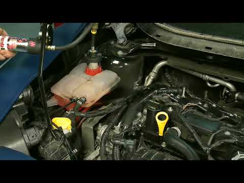
Procedure C – Battery Tray Modification – Escape and Transit Connect vehicles only
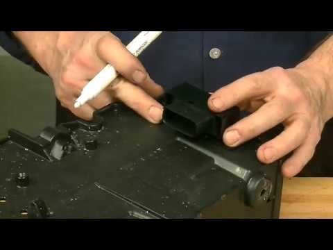
Procedure D – Coolant Stand-pipe Wire Harness Installation
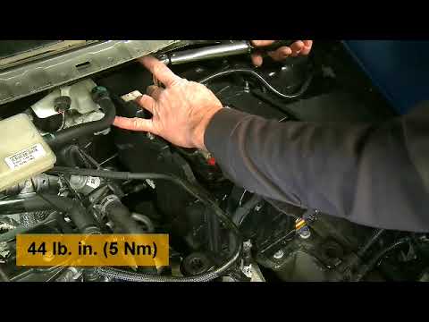
Procedure E – Instrument Panel Cluster (IPC) Reprogramming

Procedure F – Turbocharger Wire Harness Taping

Procedure H – Engine Coolant Bypass Valve Replacement

Procedure I – Coolant Hose Replacement
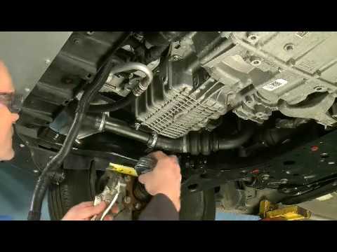
Procedure J – Coolant Stand-pipe, Degas Bottle and Cap Installation

Procedure K – Battery B+ Cable Routing Inspection and Retention – Escape vehicles only

Procedure L – Vehicle Reassembly, PCV Tube Retention, and PCM Reprogramming

ATTACHMENT VIII
CERTAIN 2013-2014 FUSION, 2013-2015 TRANSIT CONNECT, 2014 ESCAPE, AND 2014-2015 FIESTA ST VEHICLES EQUIPPED WITH A 1.6L ECOBOOST ENGINE — COOLANT LEVEL SENSOR SYSTEM INSTALLATION
2013-2014 FUSION TECHNICAL INFORMATION
OVERVIEW
In the affected vehicles, localized overheating of the engine cylinder head may cause the cylinder head to crack, causing a pressurized oil leak that may result in a fire in the engine compartment.
Service parts and repair procedures are now available to address this safety recall. Dealers are to perform repairs following the technical information in this document that include enhancements to the engine cooling and control systems. This service must be performed on all affected vehicles at no charge to the vehicle owner.
Due to the complexity of this repair, the following considerations have been made to help the repair procedure go as smoothly as possible:
- Repair procedures have been divided alphabetically into multiple separate procedures.
- Parts have been packaged into kits.
- Each procedure includes:
- Overview
- List and photo of the parts required
- List of unique tools needed
- Service tips to help complete the repair
NOTE: Please read this procedure in its entirety, prior to performing repairs. Additionally, instructional videos have been developed to assist with the repair. Please refer to Attachment VII:
Instructional Video Links to view the videos.
Recommended Tools:
| General Tools | General Equipment |
| 1/4” Drive Ratchet (Power and Hand Tool) | Floor Jack |
| 1/4″ Drive 7, 8, and 10 mm Shallow Sockets | Wood Block |
| 1/4″ Drive 10 mm, 12 mm Deep Sockets | Coolant Pressure Tester |
| 1/4″ Drive 8 mm Swivel Socket | Drain Pan |
| 1/4″ Drive E8 Inverted Torx Socket | Battery Charger |
| 1/4″ Drive T-30 Torx Bit Sockets | Extension Cord |
| 1/4″ Drive 4 in (101 mm) and 16 in (406 mm) Extensions | Tape/Electrical Tape |
| 3/8″ Drive Ratchet (Power and Hand Tool) | |
| 3/8″ Drive 11 mm, 13 mm, and 15 mm Deep Impact Socket | |
| 3/8″ Drive 15 mm Shallow Impact Socket | Special Tools |
| 3/8″ Drive 15 mm Swivel Impact Socket | Hydrometer/Refractometer |
| 3/8″ Drive 1 in (25 mm) Extension | Vacuum Tester/Re-filler |
| 1/2″ Drive Ratchet Power Tool and Hand Tool | IDS and VCM II |
| 1/4″ and 1/2″ Drive Impact Swivel | |
| 1/2″ Drive 18 mm Deep Impact Socket | |
| 1/2″ Drive 15mm Shallow Impact Socket | |
| 1/2″ Drive 6″ (152 mm) and 10″ (254 mm) Impact Extensions | |
| 1/2″ Drive Torque Wrench | |
| 1/4″ And 3/8″ Drive Torque Wrench | |
| 15 mm Ratchet Wrench | |
| 17 mm Wrench 15 in (381 mm) | |
| Channel Lock Pliers | |
| Trim Tool 7 in (177 mm) and 12 in (304 mm) | |
| Inspection Mirror | |
| Screwdriver 8 in (203 mm) | |
| Paint Stick/Pen | |
| Scissors | |
| Cable Operated Hose Pliers | |
| 4 in (101 mm) Pick Tool | |
| Pocket Screwdriver | |
| Side Cutters | |
| Needle Nose Pliers 8 in (203 mm) and 11 in (279 mm) | |
| Hose Hook Tool |
SERVICE PROCEDURE
Procedure A – Initial Disassembly and Preparation for Inspection
OVERVIEW: This procedure details the components to be removed to enable initial vehicle inspection.
PARTS / SUPPLIES REQUIRED: None
UNIQUE TOOL REQUIREMENTS: None
SERVICE TIPS: Please note the following:
- The Inspection / Check Sheet (Attachment IV) must be printed and started during “Procedure A”.
- The air cleaner, mass air flow sensor and air intake tube are removed as an assembly.
- Cover the turbocharger inlet opening to prevent dropping any parts or debris into the turbocharger while the turbocharger inlet pipe is off.
- Print a copy of the Inspection / Check Sheet (Attachment IV), to record vehicle information and inspection/repair information for the vehicle. The Inspection / Check Sheet is to be attached/filed with the recall repair order following completion, it does not need to be provided to Ford at this time.
- Fill out top of Inspection / Check Sheet including:
- VIN
- Technician ID
- Repair Order Number
- Repair Date
- Vehicle Mileage
- Vehicle Build Date
- Open Recalls
- Using OASIS, document vehicle build date on the Inspection / Check Sheet.
- With the vehicle in NEUTRAL, position it on a hoist. Please follow the Workshop Manual (WSM) procedures in Section 100-02.
- Using IDS/scan tool, retrieve and record DTCs on the Inspection / Check Sheet.
- Any DTCs recorded will be used later in this procedure.
- Remove the engine appearance cover.
All Vehicles
NOTICE: When working with liquid or vapor tube connectors, make sure to use compressed air to remove any foreign material from the connector retaining clip area before separating from the tube or damage to the tube or connector retaining clip can occur. Apply clean engine oil to the end of the tube before inserting the tube into the connector.
NOTICE: Whenever turbocharger air intake system components are removed, always cover open ports to protect from debris. It is important that no foreign material enter the system. The turbocharger compressor vanes are susceptible to damage from even small particles. All components should be inspected and cleaned, if necessary, prior to installation or reassembly.
- Detach the EVAP line from the clip on the air intake tube center section. See Figure A1.
- Loosen the clamp and disconnect the air intake tube from the turbocharger inlet pipe. See Figure A1.
 FIGURE A1
NOTE: The air cleaner assembly is removed from the vehicle with the mass air flow sensor and air intake tube attached.
- Remove the air cleaner assembly. See Figure A2.
- Remove the two bolts
- Disconnect the mass air flow sensor electrical connector and wire harness retainer from the air cleaner assembly.
- Disconnect the EVAP hose from the air cleaner outlet tube.
- Lift upward to disengage the retaining grommets and remove the air cleaner assembly.
 FIGURE A2
NOTICE: Whenever turbocharger air intake system components are removed, always cover open ports to protect from debris. It is important that no foreign material enter the system. The turbocharger compressor vanes are susceptible to damage from even small particles. All components should be inspected and cleaned, if necessary, prior to installation or reassembly.
- Remove the turbocharger air inlet pipe. See Figure A3.
- Disconnect the crankcase ventilation tube quick release coupling.
- Remove the turbocharger air inlet pipe retaining nut, the turbocharger air inlet pipe ball stud,
- Loosen the turbocharger air inlet pipe clamp and remove the turbocharger air inlet pipe.
 FIGURE A3
- Remove the retainers and the front underbody air deflectors. See Figures A4 and A5.
 FIGURE A4
 FIGURE A5
- Detach the three wire harness retainers, disconnect the crankshaft position sensor, turbocharger wastegate regulating valve solenoid, and turbocharger bypass valve electrical connectors.
See Figure A6.
 FIGURE A6
- Remove the three nuts and position the Powertrain Control Module (PCM) aside. See Figure A7.
 FIGURE A7
Procedure B – Inspection / Check Sheet Completion
OVERVIEW: The Inspection must be completed and documented on the Inspection / Check Sheet. The inspection will check for obvious concerns that require correction with additional focus on cooling system concerns such as:
- Internal coolant leaks
- External coolant leaks
- Any DTC(s) that could indicate a recent engine overheat event or internal engine damage that may have resulted from a previous cooling system concern.
PARTS / SUPPLIES REQUIRED: None
UNIQUE TOOL REQUIREMENTS: Rotunda Cooling System Pressure Tester (STN12270) and adapter (Snap-On TA52, AST ASSFZ-47, Redline RDL95-0750 or equivalent).
SERVICE TIPS: Use standard Workshop Manual and PC/ED Diagnostics, if necessary, to diagnose any cooling system or misfire DTC(s) retrieved and for any coolant loss concerns.
NOTE: Perform an underhood visual inspection for any obvious coolant, oil, transmission, or fuel leaks.
NOTE: If any concerns are identified repair as related damage before proceeding. If the coolant pressure test identifies concerns with the degas bottle, turbocharger return tube, upper section of the degas bottle return hose, or quick connect T-fitting at the coolant shutoff solenoid valve; note the condition. These items will be replaced as part of this recall. Refer to Dealer Bulletin Attachment I, Related Damage, for related damage claiming.
Vehicle Inspection
- Visually inspect the coolant level in the degas bottle.
- If the coolant level is visible in the degas bottle, proceed to Step 2.
- If the coolant level is not visible in the degas bottle, add coolant as necessary, and proceed to
Step 2.
NOTE: Any gross loss of coolant must be identified and repaired prior to proceeding.
- Remove the degas bottle cap.
- Install a coolant pressure tester with adapter onto the degas bottle. Pressurize to 138 kPa (20 psi).
Once stabilized, pressure should hold at 138 kPa (20 psi) for a minimum of 2 minutes.- If cooling system pressure does not hold for a minimum of 2 minutes, the source of pressure loss must be identified and repaired as necessary before proceeding.
- Visually check for coolant leaks with the system under pressure.
- Check the engine oil level to ensure it is within normal range, note if it is overfilled. Visually check for engine oil leaks at the rear surface of the cylinder head, above exhaust manifold, that may be the result of a crack in the cylinder head. See Figure B1.
- If an oil leak is detected at the rear surface of the cylinder head, replace the complete cylinder head assembly before proceeding.
NOTE: The turbocharger coolant tubes and exhaust manifold heat shield are removed for clarity.
FIGURE B1
- DTCs – Note and identify the cause of the following DTCs before proceeding:
- If additional DTCs are present, diagnose and repair as required.
NOTE: Diagnosis for any of the following DTCs may require reinstallation of the air intake components and battery. Perform diagnosis and repairs as necessary.
Cooling System DTCs
| P0217 | Engine Coolant Over Temperature Condition |
| P0218 | Transmission Fluid Over Temperature Condition |
| P0219 | Engine Over Speed Condition |
| P1299 | Cylinder Head Over Temperature Protection Active |
Engine Misfire DTCs
| P0300 | Random Misfire Detected |
| P030x | Cylinder X Misfire Detected |
| P0313 | Misfire Detected With Low Fuel |
| P0316 | Misfire Detected On Startup (First 1000 Revolutions) |
- Note any issues and/or repairs made on the Inspection / Check Sheet.
Procedure C – Powertrain Control Module Connector Back Shell Replacement – (Manual Transmission Vehicles Only)
OVERVIEW: Powertrain Control Module (PCM) connector back shell replacement is only required for vehicles equipped with a manual transmission. The new PCM connector back shell will allow for clearance between the PCM connector back shell and the new stand-pipe.
| A | PCM Connector Back Shell |
| B | Tie-Strap |
UNIQUE TOOL REQUIREMENTS: None
SERVICE TIPS: None
- Disconnect the battery cable to ground. Please follow the procedures in WSM Section 414-01.
- Disconnect the lower PCM electrical connector. See Figure C1.
 FIGURE C1
- Replace the connector back shell with the new connector back shell. Secure the PCM connector wires to the back shell and the new tie-strap. See Figure C2.
 FIGURE C2
- Connect the lower PCM electrical connector. See Figure C1.
NOTE: Do not reconnect the battery cable to ground at this time. It will be reconnected later in the procedure.
Procedure D – Coolant Stand-pipe Wire Harness Installation
OVERVIEW: The coolant stand-pipe wire harness is partially installed in this procedure. This is necessary to complete the connections at the electronic power assist steering (EPAS) electrical connectors which are a part of the CAN Network. The CAN Network must be complete to allow module programming.
PARTS / SUPPLIES REQUIRED:

| A | Coolant Stand-pipe Wire Harness |
| B | Junction Box |
| C | Tie-Straps x2 |
UNIQUE TOOL REQUIREMENTS: None
SERVICE TIPS: None
- If not done previously, disconnect the battery cable to ground. Please follow the procedures in WSM Section 414-01.
- Install the junction box and coolant stand-pipe wiring harness. See Figure D1.
- Position the junction box onto the engine wire harness, behind the Powertrain Control Module (PCM) and secure with the two tie-straps.
- Connect the electrical connector to the connector junction box.
- Route the coolant stand-pipe wire harness downward to the EPAS and secure to the bulkhead
wire harness and A/C line as shown in Figure D1.
 FIGURE D1
- Disconnect the EPAS electrical connector and connect the coolant stand-pipe wiring harness to the EPAS module and the EPAS electrical connector. See Figure D2.
 FIGURE D2
- Route the coolant stand-pipe wire harness stand pipe electrical connector and ground eyelet wire along the lower PCM connector wire harness. Secure the stand-pipe wire harness as shown in Figure D3.
 FIGURE D3
- NOTICE: Ensure the surface is clean and free of any dirt and debris prior to re-installing the ground bolt.
Install the new coolant stand-pipe wire harness ground eyelet to the vehicle using the existing wire harness ground bolt. See Figure D4.
- Remove and reattach the upper PCM connector harness retaining clip to access the ground bolt.
- When installing tighten to 106 lb.in (12 Nm)
 FIGURE D4
- Position the stand-pipe wire harness electrical connector aside. It will be connected later.
- Remove the nut and disconnect the generator battery cable and electrical connector. See Figure D5.
- Cover the cable end using electrical tape.
 FIGURE D5
- Connect the battery cable to ground. Please follow the procedures in WSM Section 414-01.
Procedure E – Instrument Panel Cluster (IPC) Reprogramming
OVERVIEW: The IPC software is being updated to coordinate cooling system improvements and instrument cluster messaging. IPC reprogramming can be performed while performing other repairs on the vehicle. The PCM must be reprogrammed during Procedure L after cooling system repairs and bleeding are completed.
PARTS / SUPPLIES REQUIRED: None
UNIQUE TOOL REQUIREMENTS:
- IDS with release 108.03 or higher
- Portable battery charger (10 to 20 amps)
SERVICE TIPS: Begin IPC reprogramming and continue to perform repairs during IPC reprogramming.
Reprogramming times for the IPC can be significantly reduced by using a VCM II instead of a VCM.
Important Information for Module Programming
NOTE: When programming or reprogramming a module, use the following basic checks to ensure programming completes without errors.
- Make sure the 12V battery is fully charged before carrying out the programming steps and connect IDS/scan tool to a power source.
- Inspect Vehicle Communication Module (VCM) and cables for any damage. Make sure scan tool connections are not interrupted during programming.
- A hardwired connection is strongly recommended.
- Turn off all unnecessary accessories (radio, heated/cooled seats, headlamps, interior lamps, HVAC system, etc.) and close doors.
- Disconnect/depower any aftermarket accessories (remote start, alarm, power inverter, CB radio, etc.).
- Follow all scan tool on-screen instructions carefully.
- Disable IDS/scan tool sleep mode, screensaver, hibernation modes.
- Create all sessions key on engine off (KOEO). Starting the vehicle before creating a session will cause errors within the programming inhale process.
- Ensure the headlamps and accessories are turned off.
Module Reprogramming
NOTE: The IDS must be updated to software level 108.03 or later to perform the FSA. If the IDS is not updated when the FSA is performed, it may result in various DTCs and drivability concerns. It is important that all steps of this FSA are performed in the order listed. This will ensure proper operation of the vehicle once completed.
NOTE: Reprogram appropriate vehicle modules before performing diagnostics and clear all Diagnostic Trouble Codes (DTCs) after programming. For DTCs generated after reprogramming, follow normal diagnostic service procedures.
- The IPC reprogramming can take up to 1 hour or more. Connect a portable battery charger of 10 to 20 amps to an extension cord and to the 12V battery. This will allow the vehicle to be raised and lowered as needed while completing the remaining repair procedures, and ensure uninterrupted reprogramming is achieved. Programming times can be significantly reduced by using a VCMII.
NOTE: Periodically check the status of the reprogramming progress to continue the process, as required.
- Reprogram the IPC using IDS release 108.03 or higher.
NOTE: Follow the IDS on-screen instructions to complete the reprogramming procedure.
Recovering a module when programming has resulted in a blank module:
NEVER DELETE THE ORIGINAL SESSION!
a. Obtain the original IDS tool which will have the original IDS session, that was used when the programming error occurred during module reprogramming (MR) or programmable module installation (PMI).
b. Disconnect the VCM from the data link connector (DLC) and the IDS.
c. Reconnect the VCM to IDS and then connect to the DLC. Once reconnected, the VCM icon should appear in the corner of the IDS screen. If it does not, troubleshoot the IDS to VCM connection.
d. Locate the original vehicle session when programming failed. This should be the last session used in most cases. If not, use the session created on the date that the programming failed.
NOTE: If the original session is not listed in the previous session list, click the Recycle Bin icon at the lower right of the previous session screen. This loads any deleted sessions and allows you to look through them. Double-click the session to restore it.
e. Once the session is loaded, the failed process should resume automatically.
f. If programming does not resume automatically, proceed to the Module Programming menu and select the previously attempted process, PMI or MR.
g. Follow all on-screen prompts/instructions.
h. The last screen on the IDS may list additional steps required to complete the programming process.
Make sure all applicable steps listed on the screen are followed in order.
Procedure F – Turbocharger Wire Harness Taping
OVERVIEW: This procedure wraps the turbocharger wire harness with Coroplast tape to prevent the entry/buildup of fluids and debris in the convolute which could ignite from an ignition source.
PARTS / SUPPLIES REQUIRED:
| A | Coroplast Tape |
| B | Wire Harness Retainer w/Tie-Strap |
UNIQUE TOOL REQUIREMENTS: None
SERVICE TIPS: Tips for wrapping the harness are included in the procedure.
NOTE: Figure F1 is for reference only the harness retainers were previously disconnected in Procedure A.
FIGURE F1
- Route the turbocharger wire harness to the top of the engine compartment. See Figure F2.
- If broken, replace the wire harness retainer with the new one supplied in the vehicle parts kit.
See Figures F1 and F2.- Mark the wire harness retainer location before removal.
- Wrap the turbocharger wire harness convolute with the Coroplast tape provided in the service kit.
See Figure F2.- Start and finish each length of tape applied with three (3) initial and three (3) finishing wraps.
- Apply each wrap of tape with a 50% overwrap.
- First, wrap the takeout for the crankshaft position sensor. Begin the wrap at the connector and end this portion of wrapping by going around the main harness at the takeout.
See Figure F2, (A). - Wrap the turbocharger harness starting at the side of the harness closest to the engine.
Proceed down the remaining length of harness to the turbocharger wastegate regulating valve solenoid connector and turbocharger bypass valve electrical connectors. See Figure F2, (B).
 FIGURE F2
- Route the wire harness back down to the crankshaft position sensor, turbocharger wastegate regulating valve solenoid, and turbocharger bypass valve. See Figure F1.
- Connect the crankshaft position sensor, turbocharger wastegate regulating valve solenoid, and turbocharger bypass valve electrical connectors. Attach the wire harness retainers to the engine.
See Figure F1.
Procedure G – Thermostat Replacement
OVERVIEW: An updated 82° C (179.6° F) thermostat will be installed to improve cooling system performance
PARTS / SUPPLIES REQUIRED:
| A | Thermostat |
| B | Thermostat housing to cylinder block O-rings (2 ea.) |
| C | Thermostat Housing to coolant valve O-Ring (1 ea.) |
UNIQUE TOOL REQUIREMENTS: None
SERVICE TIPS: Make sure the air bleed hole in the thermostat is in the “UP” position when installed to
allow any air trapped in the system to pass.
- Remove the thermostat housing. Please follow the WSM procedures in 303-03.
- Discard the thermostat housing gaskets.
- Use a 13 mm (1/2 in) deep well socket to press downward on the thermostat retaining clip and rotate to remove it from the thermostat housing. Remove the thermostat spring. See Figure H2.
- Note the position of the thermostat retaining clip and thermostat prior to removing.
See Figures G1 and G2.
- Note the position of the thermostat retaining clip and thermostat prior to removing.
FIGURE G1
- Remove and discard the thermostat. See Figure G2.
- Position the new thermostat into the housing with the air bleed hole positioned upward. Use a 13 mm (1/2 in) deep well socket to install the thermostat spring and clip. The retaining clip must be in the same orientation that it was in prior to removal. See Figures G2 and G3.
FIGURE G2
NOTICE: Do not use pliers or other tools to install the thermostat.
NOTE: The thermostat retaining clip must be installed in the position as shown. See Figure G3.
FIGURE G3
- Install the new thermostat housing gaskets and install the thermostat housing. Please follow the WSM procedures in 303-03.
- Do not re-connect the degas bottle to thermostat housing coolant hose at this time.
- Do not re-connect the generator battery cable and electrical connector to the generator at this time.
- Do not refill the engine coolant at this time.
Procedure H – Engine Coolant Bypass Valve Replacement
OVERVIEW: The engine coolant bypass valve is being replaced in this procedure.
PARTS / SUPPLIES REQUIRED:
| A | Engine Coolant Bypass Valve |
| B | Hose Clamp |
UNIQUE TOOL REQUIREMENTS: None
SERVICE TIPS: None
- Disconnect the engine coolant bypass valve electrical connector. See Figure H1.
FIGURE H1
- Release the clamp and disconnect the coolant hose. Discard the clamp. See Figure H2.
FIGURE H2
- Remove the bolts from the engine coolant bypass valve. Remove and discard the valve and O-ring seal. See Figure H3.
- Tighten to 89 lb.in (10 Nm).
FIGURE H3
- Install a new engine coolant bypass valve and O-ring seal by reversing the removal procedure.
Procedure I – Coolant Hose Replacement
OVERVIEW: In this procedure, the coolant hose that runs between the degas bottle and thermostat quick connect T-fitting is replaced with an updated hose that allows for connection to the turbocharger coolant return line and the new coolant stand-pipe. The engine degas tube is also being replaced with an updated assembly that allows for connection to the radiator degas hose and degas bottle.
PARTS / SUPPLIES REQUIRED:

| A | Coolant Degas Bottle to Thermostat Housing Hose |
| B | Engine Degas Tube |
UNIQUE TOOL REQUIREMENTS: None
SERVICE TIPS: The degas bottle hose assembly will need to be separated (an upper and lower portion) at the reusable clamp to allow it to be fitted to the vehicle. The clamp will be re-used during the installation. The new coolant hoses and connection points are called out below. See Figures I1A and I1B.
 FIGURE I1A
 FIGURE I1B
- Remove and discard the degas bottle and cap. See Figure I2.
 FIGURE I2
- Disconnect and position aside the turbocharger coolant return hose. See Figure I3.
 FIGURE I3
- Disconnect the degas bottle coolant hose from the radiator and discard. See Figure I4.
 FIGURE I4
- Detach the retainers, remove and discard the engine degas tube assembly. See Figure I5.
 FIGURE I5
- Detach the retainer, then route the degas hose assembly out from under the A/C line, to allow for easier removal. See Figure I6.
 FIGURE I6
- Detach the retaining clip and disconnect the degas bottle hose from the engine oil cooler assembly.
Remove and discard the degas hose assembly. See Figure I7.
 FIGURE I7
NOTE: Lubricating the new coolant hoses with coolant will aid in easier installation.
NOTE: Ensure the inside of the hose fittings are free from dirt and debris.
- Install the new lower portion of the degas bottle hose. See Figure I8.
- Route the turbocharger coolant return hose upward to the top of the engine.
- Position the lower portion of the degas bottle hose. Attach the lower retaining clip.
- Connect the lower hose to the engine oil cooler.
 FIGURE I8
- Connect the thermostat quick connect fitting to the thermostat housing. See Figure I9.
 FIGURE I9
- Route the lower degas hose upward around the A/C line and to the degas bottle area. Install the lower degas hose push pin retainers to the A/C line bracket and generator stud. See Figure I10.
- Connect the new turbocharger coolant return hose and attach the retaining clip. See Figure I10.
NOTE: The coolant stand-pipe is shown installed for reference only. It will be installed later in this procedure.
 FIGURE I10
- Install and connect the new upper portion of the new degas hose, to the previously installed new
lower degas hose. Align the hose with the marks and install the hose clamp. See Figure I11.
NOTE: The coolant stand-pipe is shown installed for reference only. It will be installed later in this procedure.
 FIGURE I11
- Install the new engine degas tube assembly and connect to the back of the engine. Connect the engine degas tube assembly to the radiator. Attach the retaining clips. See Figure I12.
 FIGURE I12
Procedure J – Coolant Stand-pipe, Degas Bottle and Cap Installation
OVERVIEW: The coolant stand-pipe provides coolant level information to the PCM and IPC via the CAN network, this prevents overheat issues due to low coolant level by informing the driver when the coolant level is low. The coolant stand-pipe and bracket is installed using the engine mount rear fixing bolt. On installation, the wiring harness is routed across the engine bay wiring loom and the related coolant hoses are attached.
PARTS / SUPPLIES REQUIRED:

| A | Coolant Stand-pipe (Includes Coolant Level Sensor) |
| B | Coolant Stand-pipe Bracket |
| C | Coolant Stand-pipe to Bracket Bolt |
| D | Engine Mount Bolt |
| E | Degas Bottle |
| F | Degas Bottle Cap |
- Remove the rear engine mount bolt and take note of the bolt hole location. The bolt hole must be centered with the engine mount hole to allow for proper installation of the coolant stand-pipe bracket.
See Figure J1.- If the bolt hole is centered with the engine mount, then powertrain assembly mount neutralizing will not be required. Proceed to Step 2.
- If the hole is not centered, carry out the powertrain assembly mount neutralizing procedure.
Please follow the WSM procedures in Section 303-00. Then proceed to Step 2.
 FIGURE J1
- NOTICE: The bolt hole must be centered with the engine mount hole to allow for proper installation of the coolant stand-pipe bracket. DO NOT use power tools to re-install the bolt.
Position the coolant stand-pipe bracket on the engine mount. The bolt will center the bracket and the locating tab on the bottom of the bracket should be pressed against the engine mount. Hand start the bolt and then tighten both engine mount retaining bolts at this time. See Figure J2.
 FIGURE J2
- Install the coolant stand-pipe to the bracket. See Figure J3.
- Push the coolant stand-pipe fully down in to position on the bracket.
- Tighten the bolt to 5 Nm (44 lb.in).
 FIGURE J3
NOTE: Lubricating the new coolant hoses with coolant will aid in easier installation.
NOTE: When connecting the coolant hoses to the stand-pipe ensure the hoses are fully installed and meet the hose stops, before securing in place with hose clamps.
NOTE: Make sure that no strain is placed on the coolant hose and pipe.
- Connect the new coolant hoses to the new coolant stand-pipe. See Figure J4.
 FIGURE J4
- Connect coolant stand-pipe wiring harness to the coolant stand-pipe. See Figure J5.
 FIGURE J5
- NOTE: Do Not fill the cooling system at this time.
Install the new degas bottle, install the bolt and cap. Connect the coolant hoses. See Figure J6.
- Tighten to 9 Nm (80 lb.in).
 FIGURE J6
NOTE: Check the status of the IPC reprogramming progress.
Procedure L – Vehicle Reassembly, PCV Tube Retention, and Powertrain Control Module (PCM) Reprogramming
OVERVIEW: The vehicle is reassembled, the cooling system is vacuum filled, pressure tested and bled; and a PCV tube retainer is installed. The PCM is reprogrammed and coolant level sensor operation is validated.
PARTS / SUPPLIES REQUIRED:
| A | PCV Tube Retainer / Tie strap |
| B | Motorcraft Metal Brake Parts Cleaner (PM-4-A or PM-4-B) (Dealer Procured) (Not Shown) |
| C | Motorcraft Orange Antifreeze / Coolant Prediluted (VC-3DIL-B (U.S.) CVC-3DIL-B (Canada) / WSS-M97B44-D2) (Dealer Procured) (Not Shown) |
UNIQUE TOOL REQUIREMENTS: Vacuum Filling Tool, Hydrometer and/or Refractometer, Cooling
System Pressure Tester
SERVICE TIPS: Follow procedure steps to verify proper coolant fill.
NOTE: This procedure contains unique steps for reassembly, including installation of new components.
- Disconnect the battery cable to ground. Please follow the WSM procedures in Section 414-01.
- Position the PCM back onto the bracket and install the three nuts. See Figure A7.
- Tighten to 10 Nm (89 lb-in).
- Uncover the generator battery cable end then connect to the generator, install the nut.
See Figure D5.- Tighten to 15 Nm (133 lb-in).
- Connect the generator electrical connector. See Figure D5.
- Connect the battery negative cable to ground. Please follow the WSM procedures in Section 414-01.
NOTE: Remove protective covers that were placed over the turbocharger air intake system before re-installing components.
- Install the turbocharger inlet pipe and connect the PCV hose to the turbocharger inlet pipe.
See Figure A3.- Tighten the turbocharger inlet pipe fasteners to 5 Nm (44 lb-in).
- Tighten the turbocharger inlet pipe-to-turbocharger clamp to 5 Nm (44 lb-in).
- Install the air cleaner and outlet pipe assembly. See Figures A1 and A2.
- Tighten the bolts and clamp to 5 Nm (44 lb-in).
- Connect the vent tube to the air cleaner outlet pipe
- Connect the EVAP line to the air tube center section.
- Connect the mass air flow electrical connector.
- Vacuum fill the cooling system. Refer to WSM Section 303-03 for coolant specifications.
- Do not bleed the cooling system at this time.
- Coolant level should be filled to the “MAX” mark on the degas bottle.
- Install a coolant pressure tester with adapter onto the degas bottle. Pressurize to 138 kPa (20 psi).
Once pressure stabilizes, pressure should hold at 138 kPa (20 psi) for a minimum of 2 minutes.- If pressure test fails, the source of pressure loss must be identified and repaired as appropriate
before proceeding. Retest the cooling system, if required.
- If pressure test fails, the source of pressure loss must be identified and repaired as appropriate
- Install the PCV tube retainer / tie strap provided in the vehicle parts kit. See Figure L1.
- Attach the clamp onto the PCV tube and secure.
- Wrap the tie strap around the air intake tube center section and tighten.
- Trim the excess length from the tie strap.
FIGURE L1
- Install the front under-body air deflector and retainers. See Figure A5.
- Bleed the cooling system. Please follow the WSM procedures in Section 303-03.
- Reprogram the PCM using IDS release 108.03 or higher. For additional information, Refer to “Procedure E” (Important Information for Module Reprogramming).
- Reprogram the Gateway Module (GWM) using IDS release 108.03 or higher. For additional information, Refer to “Procedure E” (Important Information for Module Reprogramming).
- Using IDS select “Coolant Level Sensor Check”. See Figure L2.
- Follow the on screen instructions to complete the “Coolant Level Sensor Check” procedure.
FIGURE L2
PASS COOLANT LEVEL SENSOR CHECK
DOES NOT PASS COOLANT LEVEL SENSOR CHECK
NOTE: If the coolant level is too high, additional cooling system bleeding is needed. If it is proving difficult to bleed, it may be necessary to drive the vehicle up to 12.5 Miles (20 km) to remove the air from the system.
- Check coolant concentration using the hydrometer/refractometer to make sure it is at 50%.
- Remove the portable battery charger.
- Install the engine appearance cover.
- Perform any other open recalls.
- Coolant level should be filled to the “MAX” mark on the degas bottle once the engine is cold, prior to returning the vehicle to the customer.
March 27, 2017
Ford Recall 17S09 – Chronology
June – August 2016 – Ford’s North American Critical Concern Review Group (CCRG) reviewed data related to underhood fire allegations on 2014 Escape vehicles equipped with 1.6L GTDI engines. The data showed an uptick of reported underhood fires potentially related to engine overheat during the colder months in early 2016. The fires reported were primarily localized and/or potentially self-extinguishing; consistent with the engine control system identifying a potential overheat and taking action to reduce engine temperatures. CCRG requested the gathering of further information, where possible, regarding fire origin and potential cause from complaint vehicles.
September 2016 – January 2017 – Based on the investigation and information gathered to date, the team recommended and agreed to monitor reports, investigate claims, and inspect and recover parts during the coming winter season.
January 2017 – Ford South Africa announced a recall on 2013 and 2014MY Kuga vehicles equipped with the 1.6L GTDI engine for risk of underhood fire associated with localized overheating and cracking of the cylinder head. This was announced in response to an increasing number of reports on a small volume of vehicles. Ford previously conducted a recall in the United States (13V583) for 2013MY Ford Escape vehicles equipped with 1.6L engines. The 2014 MY 1.6L equipped Escape vehicles in the United States utilized different temperature sensors and control system to reduce the likelihood of an engine overheating and cracking of the cylinder head.
February 2017 – Monitoring of reports identified an increase in underhood fire allegations, potentially related to overheat, on 2013-14 Ford Fusion vehicles equipped with 1.6L GTDI engines. CCRG reviewed this new information, in conjuction with reviewing an update on Escape reports, and began to investigate potential cause for Fusion reports, including analyses of vehicles and field returned parts.
March 2017 – A Technical Review Group (TRG) meeting was convened to review the new data on Fusion as well as the updated data on Escape. The TRG recommended that this concern be referred to the Field Review Committee (FRC) and that all vehicles in North America equipped with a 1.6L GTDI engine built prior to February 14, 2014, be included in the recommendation, regardless of the presence or lack of field reports.
On March 20, 2017, Ford’s FRC reviewed the concern and approved a field action.
Mar 29, 2017 | DEARBORN, Mich.
Ford Issues Three Safety Recalls and One Safety Compliance Recall in North America
DEARBORN, Mich., March 29, 2017 – Ford Motor Company is issuing three safety recalls and one safety compliance recall in North America. Details are as follows:
Ford issues safety recall for certain 2013-15 Ford Escape, Ford Fiesta ST, Ford Fusion and Ford Transit Connect 1.6-liter GTDI vehicles for under-hood fire risk
Ford is issuing a safety recall in North America for approximately 230,000 2014 Ford Escape, 2014-15 Ford Fiesta ST, 2013-14 Ford Fusion and 2013-15 Ford Transit Connect vehicles equipped with 1.6-liter GTDI engines. Ford’s investigation of these vehicles has identified a risk of under-hood fires.
In the affected vehicles, a lack of coolant circulation could cause an engine to overheat, resulting in a crack in the cylinder head. A cracked cylinder head can result in a pressurized oil leak. Oil that comes into contact with a hot engine surface increases the risk of a fire in the engine compartment.
Ford is aware of 29 reports of fire associated with this issue in the United States and Canada. No injuries have been reported.
Affected vehicles equipped with 1.6-liter GTDI engines include:
- Escape – Louisville Assembly Plant, Feb. 12, 2013 to Sept. 2, 2014
- 2014-15 Fiesta ST – Cuautitlan Assembly Plant, Jan. 22, to May 27, 2014
- Fusion – Hermosillo Assembly Plant, Feb. 15, 2012 to June 6, 2014
- Transit Connect – Valencia Assembly Plant, June 13, 2013 to Dec. 14, 2014
There are approximately 230,756 vehicles equipped with 1.6-liter GTDI engines located in North America, including 208,584 in the United States and federalized territories, 21,854 in Canada and 318 in Mexico. The Ford reference number for this recall is 17S09.
Ford will mail customers instructions from the owner’s manual on how to check and refill coolant. Customers can continue to drive their vehicles, but should see their dealer if their vehicle exhibits a coolant leak, overheating or frequently needs coolant added. When service kits are available, dealers will install a coolant level sensor with supporting hardware and software at no charge to the customer.
Ford Motor Company expands safety recall for certain 2014 Ford Fiesta, 2013-14 Ford Fusion and 2013-14 Lincoln![]() MKZ vehicles to replace door latches
MKZ vehicles to replace door latches
Ford Motor Company is expanding a previously announced safety recall regarding door latches to include approximately 211,000 more vehicles. Affected vehicles include 2014 Ford Fiesta, 2013-14 Ford Fusion and 2013-14 Lincoln![]() MKZ vehicles.
MKZ vehicles.
In the affected vehicles, the pawl spring tab in the side door latch could break. A door latch with a fractured pawl spring tab typically results in a “door will not close” condition. A door that opens while driving increases the risk of injury.
Ford is not aware of any accidents or injuries associated with this issue in the vehicles included in this supplement to safety action 15S16.
Affected vehicles include:
- 2014 Fiesta – Cuautitlan Assembly Plant, June 1, 2013 to Oct. 31, 2013
- 2014 Fusion – Flat Rock Assembly Plant, June 18, 2013 to Oct. 31, 2013
- 2013-14 Fusion – Hermosillo Assembly Plant, June 1, 2013 to Oct. 31, 2013
- 2013-14 Lincoln MKZ – Hermosillo Assembly Plant, June 1, 2013 to Oct. 31, 2013
There are 210,619 vehicles affected in this expanded recall in North America, including 191,432 in the United States and federalized territories, 10,996 in Canada and 8,191 in Mexico. The Ford reference number for this recall is 15S16.
Dealers will replace all four side door latches with a more robust service door latch at no cost to the customer.
Ford issues safety recall for certain 2017 Ford F-450 and F-550 vehicles to replace the driveshaft
Ford is issuing a safety compliance recall for approximately 548 2017 Ford F-450 and F-550 vehicles to replace the driveshaft.
Affected vehicles may experience driveline vibration caused by a powertrain system resonance condition at speeds above 75 mph. Continued operation of a vehicle at these speeds could result in a resonance frequency that may fracture transmission and/or driveline components. Fracture of the transmission and/or driveline components may result in a loss of motive power without warning while driving, or unintended vehicle movement in park if the parking brake is not applied, increasing the risk of injury or crash.
Ford is not aware of any accidents or injuries associated with this issue.
Affected vehicles include:
- 2017 F-450/F-550 – Kentucky Assembly Plant, June 6, 2016 to Feb. 21, 2017
- 2017 F-450/F-550 – Ohio Assembly Plant, Feb. 16, 2016 to Feb. 21, 2017
There are approximately 548 vehicles located in North America, including 509 in the United States and 39 in Canada. The Ford reference number for this recall is 17S08.
Dealers will replace the two-piece driveshaft with a new three-piece driveshaft and two center bearing brackets at no charge to the customer.
Ford issues safety compliance recall for certain 2017 Ford Edge vehicles to repair windshield header welds
Ford is issuing a safety compliance recall for approximately 111 2017 Ford Edge vehicles for missing windshield header welds.
Affected vehicles may have been built with missing welds in the windshield header portion of the body sheet metal. Vehicles with an improperly welded windshield header may have reduced lateral structural integrity, potentially increasing the risk of injury in a sideimpact crash.
Ford is not aware of any accidents or injuries associated with this issue.
Affected vehicles include certain 2017 Edge vehicles built at Oakville Assembly Plant, Feb. 21, 2017 to Feb. 22, 2017.
The recall involves approximately 111 vehicles located in North America, including 84 in the United States, 26 in Canada and one in Mexico. The Ford reference number for this recall is 17C05.
Dealers will repair windshield headers at no cost to the customer.
8 Affected Products
Vehicles
| MAKE | MODEL | YEAR |
| FORD | ESCAPE | 2014 |
| FORD | FIESTA | 2014-2015 |
| FORD | FUSION | 2013-2014 |
| FORD | TRANSIT CONNECT | 2013-2015 |
23 Associated Documents
Chronology
RMISC-17V209-4798.pdf 49.216KB
Chronology
Recall Acknowledgement
RCAK-17V209-6912.pdf 280.832KB
Recall 573 Report
RCLRPT-17V209-4095.pdf 218.815KB
Manufacturer Notices(to Dealers,etc)/TSB – March 28, 2017 SUBJECT: Safety Recall 17S09
RCMN-17V209-3326.pdf 107.732KB
ISSUED Interim Owner Notification Letter(Part 577)
RIONL-17V209-5855.pdf 325.491KB
ISSUED Owner Notification Letter(Part 577)
RCONL-17V209-7053.pdf 608.429KB
Recall 573 Report
RCLRPT-17V209-6010.PDF 218.815KB
Manufacturer Notices(to Dealers,etc)
RCMN-17V209-7886.pdf 31332.004KB
Manufacturer Notices(to Dealers,etc)
RCMN-17V209-1444.pdf 57291.093KB
Recall Quarterly Report #1, 2018-1
RCLQRT-17V209-4474.PDF 214.522KB
Recall Quarterly Report #4, 2018-4
RCLQRT-17V209-9060.PDF 211.46KB
Manufacturer Notices(to Dealers,etc) – June 7, 2018 SUBJECT: Safety Recall 17S09 Supplement #3
RCMN-17V209-1124.pdf 19855.648KB
Recall Quarterly Report #2, 2018-2
RCLQRT-17V209-5767.PDF 214.628KB
Recall Quarterly Report #3, 2018-3
RCLQRT-17V209-2773.PDF 211.344KB
Owner Notification Letter(Part 577)
RCONL-17V209-4589.pdf 44.025KB
Recall Quarterly Report #5, 2019-1
RCLQRT-17V209-3371.PDF 211.579KB
ISSUED Owner Notification Letter(Part 577)- Permanent Repair Letter
RCONL-17V209-1033.pdf 92.089KB
ISSUED Owner Notification Letter(Part 577)- Parts Available Letter
RCONL-17V209-1784.pdf 43.108KB
Recall Quarterly Report #6, 2019-2
RCLQRT-17V209-5268.PDF 211.67KB
ISSUED Renotification Notice
RCRN-17V209-8208.pdf 161.983KB
ISSUED Renotification Notice
RCRN-17V209-2969.pdf 288.031KB
ISSUED Renotification Notice
Latest Recalls Documents
https://www-odi.nhtsa.dot.gov/acms/cs/documentList.xhtml?docId=17V209&docType=RCL
Reprogramming
Service Information & Reprogramming
Module Reprogramming
| Diagnostic Software | Interface Device | Complete Vehicle Diagnostics | Module Programming | ||
| 1996-2017 Model Year |
2018-Present Model Year |
1996-2017 Model Year |
2018-Present Model Year |
||
| IDS/FDRS | VCM, VCM II, VCMM | X | X | X | X |
| FJDS/FDRS | Compatible J2534 Devices (Including VCM II and VCMM) |
X | X | X | |
Detailed system requirements, installation, and support information for each product is located under the diagnostics tool support tab for each product.
Integrated Diagnostic Software (IDS) / Ford Diagnosis & Repair System (FDRS)
For use with VCM I, VCM II, VMM and VCMM hardware devices only. The complete factory Ford Motor Company vehicle diagnostic tool that provides complete dealership level vehicle diagnostic coverage for all 1996 to present Ford, Lincoln![]() and Mercury
and Mercury![]() vehicles. The IDS software includes time based access to the IDS software, software updates and calibration files.
vehicles. The IDS software includes time based access to the IDS software, software updates and calibration files.
Ford J2534 Diagnostic Software (FJDS) / Ford Diagnosis & Repair System (FDRS)
For use with compatible J2534 hardware devices. FJDS software provides Ford Module Programming functionality that covers 1996 to present Ford, Lincoln![]() and Mercury
and Mercury![]() module reprogramming functions, plus complete dealership level vehicle diagnostic software for all 2018 to present Ford and Lincoln
module reprogramming functions, plus complete dealership level vehicle diagnostic software for all 2018 to present Ford and Lincoln![]() vehicles. The FJDS software license includes time based access to the FJDS software, software updates and calibration files.
vehicles. The FJDS software license includes time based access to the FJDS software, software updates and calibration files.
Latest Calibration Information
Module Build Data (As-Built)
Use VIN to obtain As-Built data
www.motorcraftservice.com

- J2534 Pass-Thru Programmer: TOPDON RLink J2534 is an advanced diagnostic and reprogramming tool that support all J2534 protocols, as well as D-PDU, CAN-FD and DoIP, ensuring compatibility with a wide range of modern vehicles. It offers extensive versatility with support for over 18 major automotive brands, including Chrysler, Ford, GM, Nissan, Toyota, Honda, Subaru, Land Rover/Jaguar, Volvo, Wuling, Volkswagen/Audi, Mercedes-Benz, and BMW. NOTE: Not compatible with Ford IDS diagnostic software
- All-in-One OEM Diagnostics: This J2534 ECU programming tool elevates your automotive repair capabilities to new heights by delivering complete OEM diagnosis. Boasting comprehensive full-system diagnostics, intuitive repair guides, advanced ECU programming and coding, common reset services, a vast library of repair information and more, this all-in-one solution empowers technicians to effortlessly tackle complex vehicle issues with ease. *Not compatible with 24V vehicles
- Proven Performance You Can Trust: Backed by over 10000 real vehicle tests and benefit from a wealth of practical experience, this OEM reprogramming tool guarantees stable and exceptional performance. Supported by TOPDON's dedicated technical experts with in-depth knowledge of both auto repair and J2534 Pass-Thru programming, the RLink J2534 provides prompt and professional assistance, ensuring a smooth setup and reliable compatibility
- Integrated Excellence, Always Up-to-Date: Featuring the exclusive RLink Platform to provide a streamlined experience with one-click driver installation and management, ensuring flawless integration with your OE software, maintaining the original performance quality. The built-in operation guide makes mastering OE software quick and easy, so you can get started right away. Plus, with lifetime free updates, your diagnostics will stay current with the latest drivers and innovations
- Efficiency Meets Versatility: Engineered to support three CAN channels simultaneously - CAN FD and CAN-CC included, giving you the edge in fast troubleshooting. To perfectly synchronized with the OE software, please diagnose with active subscriptions and make sure your computer system is running a compatible 64-bit Windows version (7, 8, 10 or later) to fully leverage the power of RLink J2534. *We don't provide extra OE software

- Advanced VCI Box, Industry-leading J2534 Pass-Thru Technology: This J2534 Pass-Thru Programmer is designed espically for technicians, independent shop owners, and DIY enthusiasts, enables fast, reliable computer-based programming. It supports all J2534 protocols—including the latest DoIP and CAN FD—ensuring full compatibility with both legacy and next-generation vehicles.
- High-Speed OEM-Level Diagnostics & Programming: Unlock true OEM functionality with comprehensive system diagnostics, guided troubleshooting, coding, adaptations, resets, and programming—all designed to slash repair time. This all-in-one tool eliminates the need for multiple OEM devices, boosting efficiency and cutting costs. Equipped with High-Speed USB, it delivers 10x more data per second than competing solutions
- Coverage for 17 Car Brands & Ultra Reliability: Works seamlessly for Chrysler, for Ford(Forscan), for GM, for Nissan, for Toyota, for Honda, for Subaru(SSM4), for Land Rover/Jaguar, for Volvo, for Wuling, for Volkswagen, for Mercedes-Benz, and for BMW. Backed by over 10000 real vehicle tests and benefit from a wealth of practical experience, this OEM reprogramming tool guarantees stable and exceptional performance
- User-Friendly RLink Platform & Expert Support: TOPDON’s proprietary driver management platform offers a clean interface and lifetime free updates. Access a rich library of real-world case studies to stay ahead of the curve. Backed by a support team with 10+ years of J2534 and automotive repair experience, we provide one-on-one assistance to resolve any technical issue.
- 6.6 ft USB-C Cable & Portable Storage Case: The RLink J2534 diagnostic tool features a 6.6ft USB 2.0 Cable and a 1.2 ft OBDII Extension Cable, allows to connection your computer easily outside the vehicle. The included handled carry case offers easy portability, storage, and hanging options—keeping your gear clean and ready to go, anywhere.

- [J2534 Pass-Thru Programmer] - TOPDON RLink J2534 is engineered for professional technicians, delivering OEM diagnostic and reprogramming capabilities. It supports all J2534 protocols, CAN-FD, DoIP, D-PDU. Compatible with 17 vehicle brands—such as Chrysler, Ford, GM, KIA, Hyundai, Nissan, Toyota, Honda, Subaru, Mitsubishi, MAZDA, Land Rover/Jaguar, Volvo, Volkswagen/Audi, Mercedes-Benz, and BMW. RLink J2534 can help reduce the cost of purchasing equipment from different brands.
- [All-in-One OEM Reprogramming and Diagnostics] - When seamlessly integrated with OEM diagnostic software, this dongle enables you to perform a wide range of functions, including ECU programming and coding, DTC reading and clearing, active tests, component matching, adaptations, rewriting, guided troubleshooting, and more. This all-in-one tool eliminates the need for multiple OEM devices, significantly boosting work efficiency.
- [Tested, Trusted, and Proven for Accuracy] - TOPDON RLink J2534 is renowned for its reliability, having successfully completed over 10,000 real-vehicle tests. The wealth of data and hands-on experience behind it ensures consistent performance and accurate results. You can trust this tool to deliver optimal performance.
- [One-Click Installation, Continuous Updates] - The exclusive TOPDON RLink platform streamlines installation with a one-click driver setup, allowing you to quickly access OEM software for diagnostic and reprogramming tasks. With lifetime free updates, your RLink J2534 stays current without any additional cost, ensuring reliable performance for the long term. *We don't provide extra OE software.
- [Works with Windows Compatibility and OEM Software Subscription] - The RLink J2534 supports three CAN channels - including CAN FD and CAN-CC, providing advantages in the process of rapid troubleshooting. Compatible with Windows 7, 8 and 10 (64-bit) and higher versions of the system. For full functionality, an active OEM software subscription is required for each supported vehicle brand. Please note that the dongle does not include OEM software, which must be purchased separately to access brand-specific diagnostic and reprogramming features.

- Dual WiFi & 10.1" Touchscreen: Provides a stable, high-speed wireless link 3x faster than bluetooth, and a responsive, professional interface. Topdon ONE obd2 scanner diagnostic tool ensures smooth, non-lagging diagnostic scan, boosting mechanic efficiency
- J2534 Pass-Thru Support: The included ONE VCI supports the J2534 standard, allowing it to function as a pass-thru device when paired with OEM diagnostic software.Through TOPDON’s RLink platform, technicians can perform dealer-level coding, expanding in-house capabilities without investing in multiple factory automotive scan tools
- OE Topology Mapping: Visualize the vehicle’s ECU network exactly as it’s built.Zoom, pan, and highlight specific modules to pinpoint component issues with precision.Topology mapping displays real-time communication between modules
- 50 Plus Service Functions: Covers high-demand services like ADAS calibration, DPF regen, TPMS reset, ABS bleed, and throttle adaptation.Expands your service menu, allows you to charge premium rates, and turns away zero jobs due to lack of tooling. Vehicle-specific functionality may vary
- Advaned ECU Coding: 10 of the most serviced brands in North America, including full ECU coding and flash hidden support for BMW, VW, Au-di, Benz, Porsche, Toyota, Ni ssan and more. Enables module replacement, feature customization, and personal settings with automatic backup or restore.Lets your shop safely offer high-margin customization services, attracting more customers and boosting profit

- Upgraded Connector Design: The connector has been changed to prevent previous issues. If you bought the earlier model and encountered problems, message us for a hassle-free replacement—we've got you covered
- Made for GM, Ford & Chrysler Dealer-Level Access - Gain OEM-level diagnostics, ECU programming, coding, and bidirectional control with official OE software. Perform system resets and module customization across The Big 3 from one compact OBD2 to USB GM, Chrysler, and Forscan tool. *Does not support ECU diagnostics and programming for GM vehicles using DoIP protocol. Please verify compatibility before purchase
- Supports 8+ OE Software Platforms with One Tool - Work seamlessly across Forscan, FJDS, FDRS, Tech2Win, SPS 2, Techline, GDS2, and Witech 2.0. This J2534 pass-thru device lets you switch between platforms in seconds, streamlining workflow and reducing hardware costs. *No OE Software Provided, OE diagnostic software require separate subscriptions
- Reliable Forscan Adapter for Ford Diagnostics - The RLink X3 is a pro-grade Forscan OBD2 adapter, providing a stable connection for Ford, Lincoln, Mazda, and other Forscan software vehicles. Ideal for programming, module coding, and advanced vehicle configuration
- Broad Coverage for 2006 to 2025 GM, Ford & Chrysler Vehicles - Equipped with J2534 and CAN-FD protocols, this OBD2 connector supports model-year 2006 and newer vehicles. Handle the latest CAN-FD control systems with full compatibility across GM, Ford, and Chrysler platforms

- ALL OF THE J2534 PROTOCOLS - This single unit has all of the protocols you need for your OEM J2534 reprogramming and diagnostics including the latest in DoIP and CanFD
- J2534 TECHNICAL SUPPORT - FREE for the life of the tool. Staffed by technicians who understand vehicle repair and J2534 Pass‑thru
- TOOLBOX WITH OEM APPLICATION DESCRIPTIONS - educational video tutorials and real-time news – Giving you the confidence and up-to-date knowledge to get the job done
- J2534 v05.00 API - The newest version of J2534 to give you the latest in pass-thru technology
- FUTURE PROOF WITH 4 CAN CHANNELS - Going beyond the 3 required by select Chrysler/FCA models, CarDAQ-Plus 3 also provides a 4th to meet the needs of future OEM applications
Last update on 2026-05-30 / Affiliate links / Images from Amazon Product Advertising API
SEOCONTENT-START
Ford Motor Company Ford Customer Service Division P. 0. Box 1904 Dearborn, Michigan 48121-1904 R. FILE 330 TOWN CENTER DR April 2017 STE 500 DEARBORN, Ml 48126-2796 * * * IMPORT ANT SAFETY RECALL * * * (PROGRAMA DE SEGUR/DAD IMPORTANTE) Safety Recall Notice 17S09 / NHTSA Recall 17V-209 Aviso de Revision de Seguridad 17S09 2014 Escape Your Vehicle Identification Number (VIN): This notice is sent to you in accordance with the National Traffic and Motor Vehicle Safety Act. Ford Motor Company has decided that a defect which relates to motor vehicle safety exists in your vehicle, with the VIN shown above. We apologize for this situation and want to assure you that, with your assistance, we will correct this condition. Our commitment, together with your dealer, is to provide you with the highest level of service and support. What is the issue? What will Ford and your dealer do? What should you do? On your vehicle, localized overheating of the engine cylinder head may cause the cylinder head to crack causing an oil leak that may result in a fire in the engine compartment. Ford Motor Company is working closely with its suppliers to produce parts for Safety Recall 17S09. Parts are expected to become available in the · fourth quarter 2017. When a repair is available, Ford Motor Company will re-notify you via mail to schedule a service appointment with your dealer to make enhancements to the engine cooling system. These enhancements will be completed free of charge (parts and labor). Coverage is automatically transferred to subsequent owners. Ford Motor Company will re-notify you via mail when replacement parts are available. In the meantime, 1) Maintain proper engine coolant level by following the Engine Coolant Check procedure in the Maintenance section of your Owner’s Manual to reduce the risk of overheating that could lead to a fire. Included with this letter is a copy of this section of your Owner’s Manual. 2) If your vehicle exhibits a coolant leak, overheating, or frequently needs coolant added, please contact your dealer and request a service appointment for diagnosis and repair. 17S09_ESIDTB1E7S091 What should you do? (Continued) Do you need a rental vehicle? Have you previously paid for this repair? What if you no longer own this vehicle? Can we assist you further? If you do not already have a servicing dealer, you can access www.Fordowner.com for dealer addresses, maps, and driving instructions. Please note: Federal law requires that any vehicle lessor receiving this recall notice must forward a copy of this notice to the lessee within ten days. Your vehicle may be equipped with a diagnostic feature called the Vehicle Health Report which can inform you about all available recalls, as well as other key vehicle health information. Please see https://owner.ford.com/vehicle-health for more information. If your dealer determines-that a coolant leak or overheating repair is required and needs your vehicle overnight, your dealer is authorized to provide a rental vehicle for your personal transportation at no charge {except for fuel and insurance) while your vehicle is at the dealership for repairs. Please see your dealer for guidelines and limitations. If you have previously paid for a coolant leak or overheating repair, you still need to have this recall performed to make enhancements to the engine cooling system. You may be eligible for a refund of previously paid repairs that were the result of manufacturer defect in parts or workmanship. Refunds will only be provided for service related to coolant leak or overheating repairs. To verify eligibility and expedite reimbursement, give your paid original receipt to your dealer. Refund requests may also be sent directly to Ford Motor Company. To request your refund from Ford, send the refund request with all required documentation, Including your original repair receipt (no photocopies), to Ford Motor Company at P.O. Box 6251, Dearborn, Michigan 48121-6251. Refund requests mailed to this address may take up to 60 days to process. Your original receipt will be returned to you. Detailed information regarding eligibility for Ford’s reimbursement program and documentation requirements may be obtained by contacting the Ford Customer Relationship Center at 1-866-436-7332. If you no longer own this vehicle, and have an address for the current owner, please forward this letter to the new owner. You received this notice because government regulations require that notification be sent to the last known owner of record. Our records are based primarily on state registration and title data, which indicate that you are the current owner. If you have difficulties getting your vehicle repaired promptly and without charge1 please contact your dealership’s Service Manager for assistance. RETAIL OWNERS: lf you have questions or concerns, please contact our Ford Customer Relationship Center at 1-866-436-7332 and one of our representatives will be happy to assist you. If you wish to contact us through the Internet, our address is: www.Fordowner,com. 17S09_ESJDTB1E7S091 Can we assist you further? (Continued) Para asistencia en Espaflol For the hearing impaired call 1-800-232-5952 (TDD). Representatives are available Monday through Friday: 8:00AM – 8:00PM (Eastern Time). FLEET OWNERS: If you have questions or concerns, please contact our Fleet Customer Information Center at 1-800-34-FLEET, choose Option #3, and one of our representatives will be happy to assist you. If you wish to contact us through the Internet, our address is: www.fleet.ford.com. Representatives are available Monday through Friday: 8:00AM – 8:00PM (Eastern Time). If you are still having difficulty getting your vehicle repaired in a reasonable time or without charge, you may write the Administrator, National Highway Traffic Safety Administration, 1200 New Jersey Ave. S.E., Washington, D.C. 20590 or call the toll free Vehicle Safety Hotline at 1-888-327-4236 (TTY: 1-800-424-9153) or go to www.safercar.gov. Reference NHTSA Safety Recall 17V209. Visite nuestro sitio web para ver este anuncio en Espariol al siguiente direcci6n: https://es.owner. ford.com/recall. Si necesita ayuda o tiene a!guna pregunta, per favor llame al Centro de Relaci6n con Clientes al 1-866-436-7332 y presione 2 para Espariol. Thank you for your attention to this important matter. 17S09_ES/DTB1E7S091 ESCAPE – ENGINE COOLANT CHECK UNDERHOOD OVERVIEW- 1.6L ECOBOOST”” A Engine coolant reservcir CHECKING THE ENGINE COOLANT Check the level of the engine coolant when the engine is cold. Make sure that the level is between the MIN and MAX marks on the coolant reservoir. If the !eve! is at the MIN mark, below the MIN mark, or empty, add coolant immediately. Note: Coolant expands when it is hot, the level may extend beyond the MAX mark. ADDING ENGINE COOLANT WARNING A To reduce the risk of personal injury, make sure the engine is cool before unscrewing the coolant pressure relief cap. The cooling system is under pressure; steam and hot liquid can come out forcefully when the cap is loosened slightly. meeting the Ford specification. Whenever coolant has been added, the coolant level in the coolant reservoir should be checked the next few times you drive the vehicle. If necessary, add enough prediluted engine coolant to bring the coolant level to the proper level. Item Capacity Ford part name or !;:quivalent Ford part number I Ford specification Engine Coolant 8.5 qt (8 L) Motorcraft Orange Antifreeze I VC-3DIL-B (U.S.) 1.6L EcoBoost Coolant Prediluted CVC-3DIL-B (Canada) / WSS-M97B44-D2 Note: Automotive fluids are not interchangeable. Do not use engine CQolant’or antifreeze or windshield washer fluid outside of its specified function and vehicle location. Refer to your Owner’s Manual for Additional Information
**************************************************************************************************************
osu Ford Motor Company Ford Customer Service Division P.O. Box 1904 Dearborn, Michigan 48121-1904 MICHAEL R MANNING November 2019 853 MAIN ST APT 2 CLINTON, MA 01510-1609 1 FMCU9GX6EUB65975 * * * IMPORTANT SAFETY RECALL REMINDER*** According to our records, your 2014 Escape has not had necessary safety recall repairs made. We urge you to have the free repair performed at your local dealership as soon as possible. KEY INFORMATION • Your vehicle is involved in an important safety recall • Your safety is important to us. Schedule an appointment to have service procedure completed • This procedure will be performed free of charge Recall Number and Description: 17S09 – Coolant Level Sensor System Installation What is the Issue? What Are We Asking You To Do? Service Assistance: On your vehicle, localized overheating of the engine cylinder head may cause the cylinder head to crack. A cylinder head crack may cause an oil leak that may result in a fire in the engine compartment. Please contact your dealer to schedule an appointment to have this important service procedure completed. If you do not already have a servicing dealer, you can access www.Fordowner.com for dealer addresses, maps and driving instructions. The vehicle owner is responsible for having this service action performed. Ford Motor Company reserves the right to deny coverage for any vehicle damage that may result from failure to have this recall performed on a timely basis. Therefore, please have this recall performed as soon as possible. If you have additional questions, please contact the Ford Motor Company Customer Relationship Center at 1-866-436-7332 and one of our representatives will be happy to assist you. For the hearing impaired call 1-800-232-5952 (TDD). Office Hours are Monday through Friday: 8:00AM – 5:00PM (Your Local Time). If you wish to contact us through the Internet, our address is: www.Fordowner.com. osu If your authorized dealer has recently completed this recall repair, please disregard this reminder. We apologize for any inconvenience this may cause and want to assure you that, with your assistance, we will correct this condition. Our commitment, together with your dealer, is to provide you with the highest level of service and support. Thank you for your attention to this important matter. Ford Customer Service Division osu Ford Motor Company Divisi6n de Servicio al Cliente de Ford P. 0. Box 1904 Dearborn, Michigan 48121 MICHAEL R MANNING Noviembre de 2019 853 MAIN ST APT 2 CLINTON, MA 01510-1609 1 FMCU9GX6EUB65975 * * * RECORDATORIO IMPORTANTE PROGRAMA DE SEGURIDAD * * * SegUR nuestros registros, nose realizaron en sur 2014 Escape las reparaciones necesarias correspondientes a la campana de seguridad. Le solicitamos que realice esta reparaci6n gratuita en su distribuidor local lo antes posible. INFORMACION CLAVE • Su vehfculo ha sido incluido en una importante campana de seguridad. • Su seguridad es muy importante para nosotros. Programe una cita para completar el procedimiento de servicio. • Este procedimiento se llevara a cabo sin costo alguno. • Si necesita ayuda o tiene alguna pregunta, par favor 1/ame al Centro de Relaci6n con Clientes al 1-866-436-7332 y presione 2 para Espanol Numero y descripci6n de la campana: 17509 – lnstalaci6n del sistema del sensor del nivel de refrigerante lCual es el problema? tOus le solicitamos hacer? Servicio de asistencia: En su vehfculo, el sobrecalentamiento localizado de la cabeza de cilindros del motor podrfa provocar el agrietamiento de la cabeza de cilindros. El agrietamiento de la cabeza de cilindros podrfa provocar una fuga de aceite que puede tener como consecuencia un incendio en el compartimiento del motor. Comunfquese con su distribuidor para programar una cita para completar este importante procedimiento de servicio. Si a(m no tiene un distribuidor para realizar el servicio, puede acceder a www.Fordowner.com para conocer las direcciones de los distribuidores, ver mapas y obtener las instrucciones para llegar. El propietario del vehhvehh es responsable de realizar estas acciones de servicio. Ford Motor Company se reserva el derecho de negar la cobertura en caso de que el vehfculo hubiese sufrido danos por no haber realizado la campana de manera oportuna. Por lo tanto, le solicitamos que realice esta campana lo antes posible. Si tiene mme preguntas, comununas, con el Centro de Relacio con Clientes de Ford Motor Company al 1-866-436-7332 y uno de nuestros representantes con gusto lo atendera. Las personas con problemas de audici6n pueden llamar al 1-800-232-5952 (TDD). El horario de atenci6n es de lunes a viernes, de 8:00 a. m. a 5:00 p. m. (hora local). Si desea comunicarse con nosotros a travra de Internet, nuestra direcciid es: www.Fordowner.com. osu Si ya realizz esta reparaciir de seguridad en su distribuidor autorizado, ignore este recordatorio. Lamentamos cualquier inconveniente causado y deseamos asegurarle que, con su ayuda, corregiremos el problema. Nuestro compromiso, junta con el de su distribuidor, es ofrecerle servicio y apoyo de alto nivel. Gracias por su atenciic en este asunto sumamente importante. Divisiyo de Servicio al Cliente de Ford
**************************************************************************************************************
Ford Motor Company Ford Customer Service Division P.O. Box 1904 Dearborn, Michigan 48121 1904 0001271 01 / / 000000006 / 4 December 2021 * * * IMPORTANT SAFETY RECALL REMINDER * * * According to our records, your 2014 Escape has not had necessary safety recall repairs made. We urge you to have the free repair performed at your local dealership as soon as possible. KEY INFORMATION l Your vehicle is involved in an important safety recall l Your safety is important to us. Schedule an appointment to have service procedure completed l This procedure will be performed free of charge Recall Number and Description: 17S09 – 1.6L GTDI UNDERHOOD FIRES What is the Issue? On your vehicle, localized overheating of the engine cylinder head may cause the cylinder head to crack. A cylinder head crack may cause an oil leak that may result in a fire in the engine compartment. What Are We Asking You To Do? Please contact your dealer to schedule an appointment to have this important service procedure completed. If you do not already have a servicing dealer, you can access owner.ford.com for dealer addresses, maps and driving instructions. The vehicle owner is responsible for having this service action performed. Ford Motor Company reserves the right to deny coverage for any vehicle damage that may result from failure to have this recall performed on a timely basis. Therefore, please have this recall performed as soon as possible. Service Assistance: If you have additional questions, please contact the Ford Motor Company Customer Relationship Center at 1-866-436-7332 and one of our representatives will be happy to assist you. For the hearing impaired call 1-800-232-5952 (TDD). Office Hours are Monday through Friday: 8:00AM – 5:00PM (Your Local Time). If you wish to contact us through the Internet, our address is: owner.ford.com. If your authorized dealer has recently completed this recall repair, please disregard this reminder. We apologize for any inconvenience this may cause and want to assure you that, with your assistance, we will correct this condition. Our commitment, together with your dealer, is to provide you with the highest level of service and support. Thank you for your attention to this important matter. Ford Customer Service Division Ford Motor Company División de Servicio al Cliente de Ford P. O. Box 1904 Dearborn, Michigan 48121 Deciembre de 2021 * * * RECORDATORIO DE CAMPAÑA DE SEGURIDAD IMPORTANTE * * * Según nuestros registros, en su 2014 Escape no se han realizado las reparaciones necesarias correspondientes a esta campaña de seguridad. Le solicitamos que realice esta reparación gratuita en su distribuidor local lo antes posible. INFORMACIÓN CLAVE l Su vehículo ha sido incluido en una importante campaña de seguridad. l Su seguridad es muy importante para nosotros. Programe una cita para completar el procedimiento de servicio. l Este procedimiento se llevará a cabo sin costo alguno. l Si necesita ayuda o tiene alguna pregunta, por favor llame al Centro de Relación con Clientes al 1-866-436-7332 y presione 2 para Español. Número y descripción de la campaña: 17S09 – INCENDIO BAJO EL COFRE DE 1.6L GTDI ¿Cuál es el problema? En su vehículo, el sobrecalentamiento localizado de la cabeza de cilindros del motor podría provocar el agrietamiento de la cabeza de cilindros. El agrietamiento de la cabeza de cilindros podría provocar una fuga de aceite que puede tener como consecuencia un incendio en el compartimiento del motor. ¿Qué le solicitamos hacer? Comuníquese con su distribuidor a fin de programar una cita para llevar a cabo este importante procedimiento de servicio. Si aún no tiene un distribuidor para realizar el servicio, puede acceder a owner.ford.com para conocer las direcciones de los distribuidores, ver mapas y obtener las instrucciones para llegar. El propietario del vehículo es responsable de realizar estas acciones de servicio. Ford Motor Company se reserva el derecho de negar la cobertura en caso de que el vehículo hubiese sufrido daños por no haber realizado la campaña de manera oportuna. Por lo tanto, le solicitamos que realice esta campaña lo antes posible. Servicio de asistencia: Si tiene preguntas, comuníquese con el Centro de Relación con Clientes de Ford Motor Company al 1-866-436-7332 y uno de nuestros representantes con gusto lo atenderá. Las personas con problemas de audición pueden llamar al 1-800-232-5952 (TDD). El horario de atención es de lunes a viernes, de 8:00 a.m. a 5:00 p.m. (hora local). Si desea comunicarse con nosotros a través de Internet, nuestra dirección es: owner.ford.com. Si ya realizó esta reparación en su distribuidor autorizado, ignore este aviso. Lamentamos cualquier inconveniente causado y deseamos asegurarle que, con su ayuda, corregiremos el problema. Nuestro compromiso, junto con el de su distribuidor, es ofrecerle servicio y apoyo de alto nivel. Gracias por su atención en este asunto sumamente importante. Ford, División de Servicio al Cliente
**************************************************************************************************************
Ford Motor Company Ford Customer Service Division P.O. Box 1904 Dearborn, Michigan 48121-1904 November 2020 * * * IMPORTANT SAFETY RECALL REMINDER * * * According to our records, your 2013 Fusion has not had necessary safety recall repairs made. We urge you to have the free repair performed at your local dealership as soon as possible. KEY INFORMATION l Your vehicle is involved in an important safety recall l Your safety is important to us. Schedule an appointment to have service procedure completed l This procedure will be performed free of charge Recall Number and Description: 17S09 – 1.6L GTDI COOLING SYSTEM What is the Issue? On your vehicle, localized overheating of the engine cylinder head may cause the cylinder head to crack. A cylinder head crack may cause an oil leak that may result in a fire in the engine compartment. What Are We Asking You To Do? Please contact your dealer to schedule an appointment to have this important service procedure completed. If you do not already have a servicing dealer, you can access www.owner.ford.com for dealer addresses, maps and driving instructions. The vehicle owner is responsible for having this service action performed. Ford Motor Company reserves the right to deny coverage for any vehicle damage that may result from failure to have this recall performed on a timely basis. Therefore, please have this recall performed as soon as possible. Service Assistance: If you have additional questions, please contact the Ford Motor Company Customer Relationship Center at 1-866-436-7332 and one of our representatives will be happy to assist you. For the hearing impaired call 1-800-232-5952 (TDD). Office Hours are Monday through Friday: 8:00AM – 5:00PM (Your Local Time). If you wish to contact us through the Internet, our address is: www.owner.ford.com. If your authorized dealer has recently completed this recall repair, please disregard this reminder. We apologize for any inconvenience this may cause and want to assure you that, with your assistance, we will correct this condition. Our commitment, together with your dealer, is to provide you with the highest level of service and support. Thank you for your attention to this important matter. Ford Customer Service Division Ford Motor Company División de Servicio al Cliente de Ford P. O. Box 1904 Dearborn, Michigan 48121 Noviembre de 2020 * * * RECORDATORIO DE CAMPAÑA DE SEGURIDAD IMPORTANTE * * * Según nuestros registros, en su 2013 Fusion no se han realizado las reparaciones necesarias correspondientes a esta campaña de seguridad. Le solicitamos que realice esta reparación gratuita en su distribuidor local lo antes posible. INFORMACIÓN CLAVE l Su vehículo ha sido incluido en una importante campaña de seguridad. l Su seguridad es muy importante para nosotros. Programe una cita para completar el procedimiento de servicio. l Este procedimiento se llevará a cabo sin costo alguno. l Si necesita ayuda o tiene alguna pregunta, por favor llame al Centro de Relación con Clientes al 1-866-436-7332 y presione 2 para Español. Número y descripción de la campaña: 17S09 – 1.6L GTDI COOLING SYSTEM ¿Cuál es el problema? En su vehículo, el sobrecalentamiento localizado de la cabeza de cilindros del motor podría provocar el agrietamiento de la cabeza de cilindros. El agrietamiento de la cabeza de cilindros podría provocar una fuga de aceite que puede tener como consecuencia un incendio en el compartimiento del motor. ¿Qué le solicitamos hacer? Comuníquese con su distribuidor a fin de programar una cita para llevar a cabo este importante procedimiento de servicio. Si aún no tiene un distribuidor para realizar el servicio, puede acceder a www.owner.ford.com para conocer las direcciones de los distribuidores, ver mapas y obtener las instrucciones para llegar. El propietario del vehículo es responsable de realizar estas acciones de servicio. Ford Motor Company se reserva el derecho de negar la cobertura en caso de que el vehículo hubiese sufrido daños por no haber realizado la campaña de manera oportuna. Por lo tanto, le solicitamos que realice esta campaña lo antes posible. Servicio de asistencia: Si tiene preguntas, comuníquese con el Centro de Relación con Clientes de Ford Motor Company al 1-866-436-7332 y uno de nuestros representantes con gusto lo atenderá. Las personas con problemas de audición pueden llamar al 1-800-232-5952 (TDD). El horario de atención es de lunes a viernes, de 8:00 a.m. a 5:00 p.m. (hora local). Si desea comunicarse con nosotros a través de Internet, nuestra dirección es: www.owner.ford.com. Si ya realizó esta reparación en su distribuidor autorizado, ignore este aviso. Lamentamos cualquier inconveniente causado y deseamos asegurarle que, con su ayuda, corregiremos el problema. Nuestro compromiso, junto con el de su distribuidor, es ofrecerle servicio y apoyo de alto nivel. Gracias por su atención en este asunto sumamente importante. Ford, División de Servicio al Cliente
**************************************************************************************************************
Ford Motor Company Ford Customer Service Division P. 0. Box 1904 Dearborn, Michigan 48121-1904 330 TOWN CENTER DR January 2018 STE 500 DEARBORN, Ml 48126-2796 * * * IMPORTANT SAFETY RECALL * * * (PROGRAMA DE SEGUR/DAD IMPORTANTE) Safety Recall Notice 17$09 / NHTSA Recall 17V-209 Aviso de Revision de Seguridad 17S09 2014 Escape Your Vehicle Identification Number (VIN): This notice is sent to you in accordance with the National Traffic and Motor Vehicle Safety Act. Ford Motor Company has decided that a defect which relates to motor vehicle safety exists in your vehicle, with the VIN shown above. We apologize for this situation and want to assure you that, with your assistance, we will correct this condition. Our commitment, together with your dealer, is to provide you with the highest level of service and support. What is the issue? What is the risk? What will Ford and your dealer do? How long will it take? What should you do? On your vehicle, localized overheating of the engine cylinder head may cause the cylinder head to crack. A cylinder head crack may cause an oil leak that may result in a fire in the engine compartment. Parts are now available to repair your vehicle. Ford Motor Company has authorized your dealer to install a coolant level sensor system free of charge (parts and labor). The time needed for this repair is less than one day. However, due to service scheduling requirements, your dealer may need your vehicle for a longer period of time. Additional time may be required to allow the engine to cool prior to performing this repair. In addition, your vehicle will/may require an inspection to determine if parts need to be ordered. Please call your dealer without delay and request a service date for Recall 17S09. Provide the dealer with your VIN, which is printed near your name at the beginning of this letter. What should you do? (Continued) Do you need a rental vehicle? Have you previously paid for this repair? What if you no longer own this vehicle? If you do not already have a servicing dealer, you can access www.Fordowner.com for dealer addresses, maps, and driving instructions. Ford Motor Company wants you to have this safety recall completed on your vehicle. The vehicle owner is responsible for making arrangements to have the work completed. Ford Motor Company can deny coverage for any vehicle damage that may result from the failure to have this recall performed on a timely basis. Therefore, please have this recall performed as soon as possible. Please note: Federal law requires that any vehicle lessor receiving this recall notice must forward a copy of this notice to the lessee within ten days. NOTE: You can receive information about Recalls and Customer downloaded through the App Store or Google Play. In addition there are other features such as reserving and paying for parking in certain locations and controlling certain functions on your vehicle (lock or unlock doors, remote start) if it is equipped to allow control. Your dealer is authorized to provide a rental vehicle for your personal transportation at no charge (except for fuel and insurance) while your vehicle is at the dealership for repairs. Please see your dealer for guidelines and limitations. If you have previously paid for a coolant leak or overheating repair, you still need to have this recall performed to make enhancements to the engine cooling system. You may be eligible for a refund of previously paid repairs. Refunds will only be provided for service related to an engine coolant leak or overheating repairs. To verify eligibility and expedite reimbursement, give your paid original receipt to your dealer. Refund requests may also be sent directly to Ford Motor Company. To request your refund from Ford, send the refund request with all required documentation, including your original repair receipt (no photocopies), to Ford Motor Company at P.O. Box 6251 , Dearborn, Michigan 48121-6251. Retund requests mailed to this address may take up to 60 days to process. Your original receipt will be returned to you. Detailed information regarding eligibility for Ford’s reimbursement program and documentation requirements may be obtained by contacting the Ford Customer Relationship Center at 1-866-436-7332. If you no longer own this vehicle, and have an address for the current owner, please forward this letter to the new owner. You received this notice because government regulations require that notification be sent to the last known owner of record. Our records are based primarily on state registration and title data, which indicate that you are the current owner. Can we assist you further? Para asistencia en Espanol If you have difficulties getting your vehicle repaired promptly and without charge, please contact your dealership’s Service Manager for assistance. RETAIL OWNERS: If you have questions or concerns, please contact our Ford Customer Relationship Center at 1-866-436-7332 and one of our representatives will be happy to assist you. If you wish to contact us through the Internet, our address is: www.Fordowner.com. For the hearing impaired call 1-800-232-5952 (TDD). Representatives are available Monday through Friday: 8:00AM – 8:00PM (Eastern Time). FLEET OWNERS: If you have questions or concerns, please contact our Fleet Customer Information Center at 1-800-34-FLEET, choose Option #3, and one of our representatives will be happy to assist you. If you wish to contact us through the Internet, our address is: www.fleet.ford.com. Representatives are available Monday through Friday: 8:00AM – 8:00PM (Eastern Time). If you are still having difficulty getting your vehicle repaired in a reasonable time or without charge, you may write the Administrator, National Highway Traffic Safety Administration, 1200 New Jersey Ave. S.E., Washington, D.C. 20590 or call the toll free Vehicle Safety Hotline at 1-888-327-4236 (TTY: 1-800-424-9153) or go to www.safercar.gov. Reference NHTSA Safety Recall 17V-209. Visite nuestro sitio web para ver este anuncio en Espanol al siguiente direcci6n: https://es.owner.ford.com/recall. Si necesita ayuda o tiene alguna pregunta, por favor llame al Centro de Relacion con Clientes al 1-866-436-7332 y presione 2 para Espanol. Thank you for your attention to this important matter. Ford Customer Service Division 17S09_ERA/DTB1A7S091
**************************************************************************************************************
Ford Motor Company Ford Customer Service Division P. O. Box 1904 Dearborn, Michigan 48121 June 2018 * * * IMPORTANT SAFETY RECALL * * * Safety Recall Notice 17S09 / NHTSA Recall 17V-209 Mr. John Sample 123 Main Street Anywhere, USA 12345 Your Vehicle Identification Number (VIN): 12345678901234567 This notice is sent to you in accordance with the National Traffic and Motor Vehicle Safety Act. Ford Motor Company has decided that a defect which relates to motor vehicle safety exists in your vehicle, with the VIN shown above. We apologize for this situation and want to assure you that, with your assistance, we will correct this condition. Our commitment, together with your dealer, is to provide you with the highest level of service and support. What is the issue? On your vehicle, localized overheating of the engine cylinder head may cause the cylinder head to crack. What is the risk? A cylinder head crack may cause an oil leak that may result in a fire in the engine compartment. What will Ford and your dealer do? Parts are now available to repair your vehicle. Ford Motor Company has authorized your dealer to install a coolant level sensor system free of charge (parts and labor). How long will it take? The time needed for this repair is less than one day. However, due to service scheduling requirements, your dealer may need your vehicle for a longer period of time. Additional time may be required to allow the engine to cool prior to performing this repair. In addition, your vehicle will/may require an inspection to determine if parts need to be ordered. What should you do? Please call your dealer without delay and request a service date for Recall 17S09. Provide the dealer with your VIN, which is printed near your name at the beginning of this letter. What should you do? (Continued) If you do not already have a servicing dealer, you can access www.Fordowner.com for dealer addresses, maps, and driving instructions. Ford Motor Company wants you to have this safety recall completed on your vehicle. The vehicle owner is responsible for making arrangements to have the work completed. Ford Motor Company can deny coverage for any vehicle damage that may result from the failure to have this recall performed on a timely basis. Therefore, please have this recall performed as soon as possible. Please note: Federal law requires that any vehicle lessor receiving this recall notice must forward a copy of this notice to the lessee within ten days. NOTE: You can receive information about Recalls and Customer Satisfaction Programs through our FordPass App. The app can be downloaded through the App Store or Google Play. In addition there are other features such as reserving and paying for parking in certain locations and controlling certain functions on your vehicle (lock or unlock doors, remote start) if it is equipped to allow control. Do you need a rental vehicle? Your dealer is authorized to provide a rental vehicle for your personal transportation at no charge (except for fuel and insurance) while your vehicle is at the dealership for repairs. Please see your dealer for guidelines and limitations. Have you previously paid for this repair? If you have previously paid for a coolant leak or overheating repair, you still need to have this recall performed to make enhancements to the engine cooling system. You may be eligible for a refund of previously paid repairs. Refunds will only be provided for service related to an engine coolant leak or overheating repairs. To verify eligibility and expedite reimbursement, give your paid original receipt to your dealer. Refund requests may also be sent directly to Ford Motor Company. To request your refund from Ford, send the refund request with all required documentation, including your original repair receipt (no photocopies), to Ford Motor Company at P.O. Box 6251, Dearborn, Michigan 48121-6251. Refund requests mailed to this address may take up to 60 days to process. Your original receipt will be returned to you. Detailed information regarding eligibility for Ford’s reimbursement program and documentation requirements may be obtained by contacting the Ford Customer Relationship Center at 1-866-436-7332. What if you no longer own this vehicle? If you no longer own this vehicle, and have an address for the current owner, please forward this letter to the new owner. You received this notice because government regulations require that notification be sent to the last known owner of record. Our records are based primarily on state registration and title data, which indicate that you are the current owner. Can we assist you further? If you have difficulties getting your vehicle repaired promptly and without charge, please contact your dealership’s Service Manager for assistance. RETAIL OWNERS: If you have questions or concerns, please contact our Ford Customer Relationship Center at 1-866-436-7332 and one of our representatives will be happy to assist you. If you wish to contact us through the Internet, our address is: www.Fordowner.com. For the hearing impaired call 1-800-232-5952 (TDD). Representatives are available Monday through Friday: 8:00AM – 8:00PM (Eastern Time). FLEET OWNERS: If you have questions or concerns, please contact our Fleet Customer Information Center at 1-800-34-FLEET, choose Option #3, and one of our representatives will be happy to assist you. If you wish to contact us through the Internet, our address is: www.fleet.ford.com. Representatives are available Monday through Friday: 8:00AM – 8:00PM (Eastern Time). If you are still having difficulty getting your vehicle repaired in a reasonable time or without charge, you may write the Administrator, National Highway Traffic Safety Administration, 1200 New Jersey Ave. S.E., Washington, D.C. 20590 or call the toll free Vehicle Safety Hotline at 1-888-327-4236 (TTY: 1-800-424-9153) or go to www.safercar.gov. Reference NHTSA Safety Recall 17V-209. Thank you for your attention to this important matter. Ford Customer Service Division
**************************************************************************************************************
March 2019 Ford Motor Company Ford Customer Service Division P. O. Box 1904 Dearborn, Michigan 48121-1904 * * * IMPORTANT SAFETY RECALL * * * Safety Recall Notice 17S09 / NHTSA Recall 17V-209 2014 Transit Connect Your Vehicle Identification Number (VIN): NM0AS8FX0E1133387 This notice is sent to you in accordance with the National Traffic and Motor Vehicle Safety Act. Ford Motor Company has decided that a defect which relates to motor vehicle safety exists in your vehicle, with the VIN shown above. We apologize for this situation and want to assure you that, with your assistance, we will correct this condition. Our commitment, together with your dealer, is to provide you with the highest level of service and support. What is the issue? On your vehicle, localized overheating of the engine cylinder head may cause the cylinder head to crack. What is the risk? A cylinder head crack may cause an oil leak that may result in a fire in the engine compartment. What will Ford and your dealer do? Parts are now available to repair your vehicle. Ford Motor Company has authorized your dealer to install a coolant level sensor system free of charge (parts and labor). How long will it take? The time needed for this repair is less than one day. However, due to service scheduling requirements, your dealer may need your vehicle for a longer period of time. Additional time may be required to allow the engine to cool prior to performing this repair. In addition, your vehicle will/may require an inspection to determine if parts need to be ordered. What should you do? Please call your dealer without delay and request a service date for Recall 17S09. Provide the dealer with your VIN, which is printed near your name at the beginning of this letter. Ford has not issued instructions to stop driving your vehicle under this safety recall. You should contact your dealer for an appointment to have your vehicle remedied as soon as practicable. You can continue to safely drive your vehicle. If you do not already have a servicing dealer, you can access www.Fordowner.com for dealer addresses, maps, and driving instructions. Ford Motor Company wants you to have this safety recall completed on your vehicle. The vehicle owner is responsible for making arrangements to have the work completed. Ford Motor Company can deny coverage for any vehicle damage that may result from the failure to have this recall performed on a timely basis. Therefore, please have this recall performed as soon as possible. Please note: Federal law requires that any vehicle lessor receiving this recall notice must forward a copy of this notice to the lessee within ten days. NOTE: You can receive information about Recalls and Customer Satisfaction Programs through our FordPass App. The app can be downloaded through the App Store or Google Play. In addition there are other features such as reserving and paying for parking in certain locations and controlling certain functions on your vehicle (lock or unlock doors, remote start) if it is equipped to allow control. JOHN A. SAMPLE 123 SAMPLE ST SAMPLE CITY, MI 12345-6789 Do you need a rental vehicle? Your dealer is authorized to provide a rental vehicle for your personal transportation at no charge (except for fuel and insurance) while your vehicle is at the dealership for repairs. Please see your dealer for guidelines and limitations. Have you previously paid for this repair? If you have previously paid for a coolant leak or overheating repair, you still need to have this recall performed to make enhancements to the engine cooling system. You may be eligible for a refund of previously paid repairs. Refunds will only be provided for service related to an engine coolant leak or overheating repairs. To verify eligibility and expedite reimbursement, give your paid original receipt to your dealer. Refund requests may also be sent directly to Ford Motor Company. To request your refund from Ford, send the refund request with all required documentation, including your original repair receipt (no photocopies), to Ford Motor Company at P.O. Box 6251, Dearborn, Michigan 48121-6251. Refund requests mailed to this address may take up to 60 days to process. Your original receipt will be returned to you. Detailed information regarding eligibility for Ford’s reimbursement program and documentation requirements may be obtained by contacting the Ford Customer Relationship Center at 1-866-436-7332. What if you no longer own this vehicle? If you no longer own this vehicle, and have an address for the current owner, please forward this letter to the new owner. You received this notice because government regulations require that notification be sent to the last known owner of record. Our records are based primarily on state registration and title data, which indicate that you are the current owner. Can we assist you further? If you have difficulties getting your vehicle repaired promptly and without charge, please contact your dealership’s Service Manager for assistance. RETAIL OWNERS: If you have questions or concerns, please contact our Ford Customer Relationship Center at 1-866-436-7332 and one of our representatives will be happy to assist you. If you wish to contact us through the Internet, our address is: www.Fordowner.com. For the hearing impaired call 1-800-232-5952 (TDD). Representatives are available Monday through Friday: 8:00AM – 8:00PM (Eastern Time). FLEET OWNERS: If you have questions or concerns, please contact our Fleet Customer Information Center at 1-800-34-FLEET, choose Option #3, and one of our representatives will be happy to assist you. If you wish to contact us through the Internet, our address is: www.fleet.ford.com. Representatives are available Monday through Friday: 8:00AM – 8:00PM (Eastern Time). If you are still having difficulty getting your vehicle repaired in a reasonable time or without charge, you may write the Administrator, National Highway Traffic Safety Administration, 1200 New Jersey Ave. S.E., Washington, D.C. 20590 or call the toll free Vehicle Safety Hotline at 1-888-327-4236 (TTY: 1-800-424-9153) or go to www.safercar.gov. Reference NHTSA Safety Recall 17V-209. Thank you for your attention to this important matter. Ford Customer Service Division JOHN A. SAMPLE 123 SAMPLE ST SAMPLE CITY, MI 12345-6789 * * * CAMPAÑA DE SEGURIDAD IMPORTANTE * * * Aviso de campaña de seguridad 17S09 / Campaña 17V-209 de la NHTSA 2014 Transit Connect Número de identificación del vehículo (VIN): NM0AS8FX0E1133387 Este aviso se le envía de acuerdo con la Ley Nacional de Seguridad y Tránsito de Vehículos de los EE. UU. Ford Motor Company ha determinado que su vehículo presenta un defecto relacionado con la seguridad del motor, con el VIN que aparece más arriba. Lamentamos esta situación y deseamos asegurarle que, con su ayuda, corregiremos el problema. Nuestro compromiso, junto con el de su distribuidor, es ofrecerle servicio y apoyo de alto nivel. ¿Cuál es el problema? En su vehículo, el sobrecalentamiento localizado de la cabeza de cilindros del motor podría provocar el agrietamiento de la cabeza de cilindros. ¿Qué riesgo existe? El agrietamiento de la cabeza de cilindros podría provocar una fuga de aceite que puede tener como consecuencia un incendio en el compartimiento del motor. ¿Qué medidas adoptarán Ford y su distribuidor? En este momento las piezas para reparar su vehículo se encuentran disponibles. Ford Motor Company ha autorizado a su distribuidor a instalar un sistema de detección de nivel de refrigerante sin costo alguno para usted (piezas y mano de obra). ¿Cuánto tiempo tomará? El tiempo necesario para esta reparación será de menos de un día. Sin embargo, debido a los requisitos de planificación de servicio, es posible que su distribuidor tarde un poco más. Es posible que se necesite más tiempo para permitir que el motor se enfríe antes de realizar esta reparación. Además, es posible que se realice una inspección del vehículo para determinar si se deben solicitar piezas. ¿Qué debe hacer? Llame a su distribuidor lo antes posible y solicite una cita de servicio para llevar a cabo la campaña 17S09. Proporcione el VIN a su distribuidor, el cual está impreso debajo de sus datos al comienzo de esta carta. Para esta campaña de seguridad, Ford no ha emitido instrucciones de no manejar el vehículo. Usted debe ponerse en contacto con su distribuidor a fin de programar una cita para solucionar este problema lo más pronto posible. Puede continuar manejando su vehículo con seguridad. Si aún no tiene un distribuidor para realizar el servicio, puede acceder a www.Fordowner.com para conocer las direcciones de los distribuidores, ver mapas y obtener las instrucciones para llegar. Ford Motor Company le recomienda realizar esta campaña de seguridad en su vehículo. El propietario del vehículo es responsable de efectuar la organización necesaria para llevar a cabo el trabajo. Ford Motor Company puede negar la cobertura en caso de que el vehículo hubiese sufrido daños por no haber realizado la campaña de manera oportuna. Por lo tanto, le solicitamos que realice esta campaña lo antes posible. Tenga presente que: la ley federal exige que los arrendadores de vehículos que reciban este aviso de campaña envíen una copia del mismo al arrendatario en un plazo de diez días. Marzo de 2019 Ford Motor Company División de Servicio al Cliente de Ford P. O. Box 1904 Dearborn, Michigan 48121 ¿Qué debe hacer? (continuación) NOTA: puede recibir información sobre las campañas y los programas de satisfacción del cliente a través de la aplicación FordPass. La aplicación se puede descargar a través de App Store o Google Play. Adicionalmente, existen otras funciones, como reserva y pago de estacionamientos en ciertos lugares, además de control de ciertas funciones en el vehículo (bloqueo y desbloqueo de puertas, arranque remoto) si así está equipado para permitir el control. ¿Necesita un vehículo de alquiler? Su distribuidor está autorizado a ofrecerle un vehículo de alquiler para su transporte personal sin costo (excepto el combustible y el seguro) mientras su vehículo se encuentre en reparación. Comuníquese con su distribuidor para conocer las pautas y limitaciones. ¿Ha pagado anteriormente por esta reparación? Si anteriormente pagó por una reparación de fuga de refrigerante o de sobrecalentamiento, igualmente debe efectuar esta campaña para realizar las mejoras al sistema de enfriamiento del motor. Es posible que cumpla con los requisitos para recibir un reembolso por las reparaciones pagadas previamente. Solo se otorgarán reembolsos de servicios relacionados con reparaciones de fuga de refrigerante o de sobrecalentamiento del motor. Para comprobar si cumple con los requisitos y agilizar el reembolso, proporcione el recibo de pago original a su distribuidor. También puede enviar las solicitudes de reembolso directamente a Ford Motor Company. Para solicitar un reembolso a Ford, envíe la solicitud de reembolso con toda la documentación requerida, incluido el recibo original de la reparación (no envíe fotocopias), a Ford Motor Company, P.O. Box 6251, Dearborn, Michigan 48121-6251. El procesamiento de las solicitudes de reembolso enviadas a esta dirección puede tardar hasta 60 días. Su recibo original le será regresado. Comuníquese con el Centro de Relación con Clientes al 1-866-436-7332 para obtener información detallada relacionada con el programa de reembolso de Ford y los requisitos de documentación. ¿Qué pasa si usted ya no es el propietario del vehículo? Si usted ya no es el propietario del vehículo y tiene la dirección del propietario actual, le solicitamos que le reenvíe esta carta. Usted recibió este aviso porque las regulaciones del gobierno exigen el envío de notificaciones al propietario conocido más reciente del registro. Nuestros registros se basan principalmente en datos estatales y de propiedad, que indican que usted es el propietario actual del vehículo. ¿Podemos hacer algo más por usted? Si tiene problemas para reparar de inmediato su vehículo y sin costo alguno, comuníquese con el Gerente de Servicio de su distribuidor para solicitar ayuda. PROPIETARIOS MINORISTAS: si tiene dudas o preguntas, comuníquese con nuestro Centro de Relación con Clientes Ford al 1-866-436-7332 y uno de nuestros representantes con gusto lo atenderá. Si desea comunicarse con nosotros a través de Internet, nuestra dirección es: www.Fordowner.com. Las personas con problemas de audición pueden llamar al 1-800-232-5952 (TDD). Los representantes atienden de lunes a viernes, 8:00 am a 8:00 pm (hora local). PROPIETARIOS DE FLOTAS: si tiene dudas o preguntas, comuníquese con nuestro Centro de Información a Clientes de flotas al 1-800-34-FLEET, elija la opción n.° 3 y uno de nuestros representantes con gusto lo atenderá. Si desea comunicarse con nosotros a través de Internet, nuestra dirección es: www.fleet.ford.com. Los representantes atienden de lunes a viernes, 8:00 am a 8:00 pm (hora local). Si continúa con dificultades para reparar su vehículo en un tiempo razonable o sin cargo, le sugerimos que escriba al Administrador, National Highway Traffic Safety Administration, 1200 New Jersey Ave. S.E., Washington, D.C. 20590 o bien que llame sin cargo a la línea directa de seguridad vehicular al 1-888-327-4236 (TTY: 1-800-424-9153) o visite www.safercar.gov. Mencione la campaña de seguridad 17V-209 de la NHTSA. Gracias por su atención en este asunto sumamente importante. Ford, División de Servicio al Cliente
**************************************************************************************************************
March 2019 Ford Motor Company Ford Customer Service Division P. O. Box 1904 Dearborn, Michigan 48121-1904 * * * IMPORTANT SAFETY RECALL * * * Safety Recall Notice 17S09 / NHTSA Recall 17V-209 2013 Fusion Your Vehicle Identification Number (VIN): 3FA6P0HR1DR389249 Our records indicate that your dealer previously performed an interim repair on your vehicle by performing a cooling system pressure test and adding coolant if needed. Even though you had an interim repair, you still need to have a permanent repair performed. This notice is sent to you in accordance with the National Traffic and Motor Vehicle Safety Act. Ford Motor Company has decided that a defect which relates to motor vehicle safety exists in your vehicle, with the VIN shown above. We apologize for this situation and want to assure you that, with your assistance, we will correct this condition. Our commitment, together with your dealer, is to provide you with the highest level of service and support. What is the issue? On your vehicle, localized overheating of the engine cylinder head may cause the cylinder head to crack. What is the risk? A cylinder head crack may cause an oil leak that may result in a fire in the engine compartment. What will Ford and your dealer do? Permanent repair parts are now available to repair your vehicle. Ford Motor Company has authorized your dealer to install a coolant level sensor system free of charge (parts and labor). How long will it take? The time needed for this repair is less than one day. However, due to service scheduling requirements, your dealer may need your vehicle for a longer period of time. Additional time may be required to allow the engine to cool prior to performing this repair. In addition, your vehicle will/may require an inspection to determine if parts need to be ordered. What should you do? Please call your dealer without delay and request a service date for Recall 17S09. Provide the dealer with your VIN, which is printed near your name at the beginning of this letter. Ford has not issued instructions to stop driving your vehicle under this safety recall. You should contact your dealer for an appointment to have your vehicle remedied as soon as practicable. You can continue to safely drive your vehicle. If you do not already have a servicing dealer, you can access www.Fordowner.com for dealer addresses, maps, and driving instructions. Ford Motor Company wants you to have this safety recall completed on your vehicle. The vehicle owner is responsible for making arrangements to have the work completed. Ford Motor Company can deny coverage for any vehicle damage that may result from the failure to have this recall performed on a timely basis. Therefore, please have this recall performed as soon as possible. Please note: Federal law requires that any vehicle lessor receiving this recall notice must forward a copy of this notice to the lessee within ten days. JOHN A. SAMPLE 123 SAMPLE ST SAMPLE CITY, MI 12345-6789 What should you do? (continued) NOTE: You can receive information about Recalls and Customer Satisfaction Programs through our FordPass App. The app can be downloaded through the App Store or Google Play. In addition there are other features such as reserving and paying for parking in certain locations and controlling certain functions on your vehicle (lock or unlock doors, remote start) if it is equipped to allow control. Do you need a rental vehicle? Your dealer is authorized to provide a rental vehicle for your personal transportation at no charge (except for fuel and insurance) while your vehicle is at the dealership for repairs. Please see your dealer for guidelines and limitations. Have you previously paid for this repair? If you have previously paid for a coolant leak or overheating repair, you still need to have this recall performed to make enhancements to the engine cooling system. You may be eligible for a refund of previously paid repairs. Refunds will only be provided for service related to an engine coolant leak or overheating repairs. To verify eligibility and expedite reimbursement, give your paid original receipt to your dealer. Refund requests may also be sent directly to Ford Motor Company. To request your refund from Ford, send the refund request with all required documentation, including your original repair receipt (no photocopies), to Ford Motor Company at P.O. Box 6251, Dearborn, Michigan 48121-6251. Refund requests mailed to this address may take up to 60 days to process. Your original receipt will be returned to you. Detailed information regarding eligibility for Ford’s reimbursement program and documentation requirements may be obtained by contacting the Ford Customer Relationship Center at 1-866-436-7332. What if you no longer own this vehicle? If you no longer own this vehicle, and have an address for the current owner, please forward this letter to the new owner. You received this notice because government regulations require that notification be sent to the last known owner of record. Our records are based primarily on state registration and title data, which indicate that you are the current owner. Can we assist you further? If you have difficulties getting your vehicle repaired promptly and without charge, please contact your dealership’s Service Manager for assistance. RETAIL OWNERS: If you have questions or concerns, please contact our Ford Customer Relationship Center at 1-866-436-7332 and one of our representatives will be happy to assist you. If you wish to contact us through the Internet, our address is: www.Fordowner.com. For the hearing impaired call 1-800-232-5952 (TDD). Representatives are available Monday through Friday: 8:00AM – 8:00PM (Eastern Time). FLEET OWNERS: If you have questions or concerns, please contact our Fleet Customer Information Center at 1-800-34-FLEET, choose Option #3, and one of our representatives will be happy to assist you. If you wish to contact us through the Internet, our address is: www.fleet.ford.com. Representatives are available Monday through Friday: 8:00AM – 8:00PM (Eastern Time). If you are still having difficulty getting your vehicle repaired in a reasonable time or without charge, you may write the Administrator, National Highway Traffic Safety Administration, 1200 New Jersey Ave. S.E., Washington, D.C. 20590 or call the toll free Vehicle Safety Hotline at 1-888-327-4236 (TTY: 1-800-424-9153) or go to www.safercar.gov. Reference NHTSA Safety Recall 17V-209. Thank you for your attention to this important matter. Ford Customer Service Division JOHN A. SAMPLE 123 SAMPLE ST SAMPLE CITY, MI 12345-6789 * * * CAMPAÑA DE SEGURIDAD IMPORTANTE * * * Aviso de campaña de seguridad 17S09 / Campaña 17V-209 de la NHTSA 2013 Fusion Número de identificación del vehículo (VIN): 3FA6P0HR1DR389249 En nuestros registros aparece que su distribuidor ya realizó una reparación provisoria en su vehículo al realizar una prueba de presión del sistema de enfriamiento y agregar refrigerante, de ser necesario. Si bien se llevó a cabo una reparación provisoria, igualmente debe realizar una reparación permanente. Este aviso se le envía de acuerdo con la Ley Nacional de Seguridad y Tránsito de Vehículos de los EE. UU. Ford Motor Company ha determinado que su vehículo presenta un defecto relacionado con la seguridad del motor, con el VIN que aparece más arriba. Lamentamos esta situación y deseamos asegurarle que, con su ayuda, corregiremos el problema. Nuestro compromiso, junto con su distribuidor, es ofrecerle los niveles de servicio y soporte más altos. ¿Cuál es el problema? En su vehículo, el sobrecalentamiento localizado de la cabeza de cilindros del motor podría provocar el agrietamiento de la cabeza de cilindros. ¿Qué riesgo existe? El agrietamiento de la cabeza de cilindros podría provocar una fuga de aceite que puede tener como consecuencia un incendio en el compartimiento del motor. ¿Qué medidas adoptarán Ford y su distribuidor? Las piezas para la reparación permanente de su vehículo ya se encuentran disponibles. Ford Motor Company ha autorizado a su distribuidor a instalar un sistema de detección de nivel de refrigerante sin costo alguno para usted (piezas y mano de obra). ¿Cuánto tiempo tomará? El tiempo necesario para esta reparación será de menos de un día. Sin embargo, debido a los requisitos de planificación de servicio, es posible que su distribuidor tarde un poco más. Es posible que se necesite más tiempo para permitir que el motor se enfríe antes de realizar esta reparación. Además, es posible que se realice una inspección del vehículo para determinar si se deben solicitar piezas. ¿Qué debe hacer? Llame a su distribuidor lo antes posible y solicite una cita de servicio para llevar a cabo la campaña 17S09. Proporcione el VIN a su distribuidor, el cual está impreso debajo de sus datos al comienzo de esta carta. Para esta campaña de seguridad, Ford no ha emitido instrucciones de no manejar el vehículo. Usted debe ponerse en contacto con su distribuidor a fin de programar una cita para solucionar este problema lo más pronto posible. Puede continuar manejando su vehículo con seguridad. Si aún no tiene un distribuidor para realizar el servicio, puede acceder a www.Fordowner.com para conocer las direcciones de los distribuidores, ver mapas y obtener las instrucciones para llegar. Ford Motor Company le recomienda realizar esta campaña de seguridad en su vehículo. El propietario del vehículo es responsable de efectuar la organización necesaria para llevar a cabo el trabajo. Ford Motor Company puede negar la cobertura en caso de que el vehículo hubiese sufrido daños por no haber realizado la campaña de manera oportuna. Por lo tanto, le solicitamos que realice esta campaña lo antes posible. Marzo de 2019 Ford Motor Company División de Servicio al Cliente de Ford P. O. Box 1904 Dearborn, Michigan 48121 ¿Qué debe hacer? (continuación) Tenga presente que: la ley federal exige que los arrendadores de vehículos que reciban este aviso de campaña envíen una copia del mismo al arrendatario en un plazo de diez días. NOTA: puede recibir información sobre las campañas y los programas de satisfacción del cliente a través de la aplicación FordPass. La aplicación se puede descargar a través de App Store o Google Play. Adicionalmente, existen otras funciones, como reserva y pago de estacionamientos en ciertos lugares, además de control de ciertas funciones en el vehículo (bloqueo y desbloqueo de puertas, arranque remoto) si así está equipado para permitir el control. ¿Necesita un vehículo de alquiler? Su distribuidor está autorizado a ofrecerle un vehículo de alquiler para su transporte personal sin costo (excepto el combustible y el seguro) mientras su vehículo se encuentre en reparación. Comuníquese con su distribuidor para conocer las pautas y limitaciones. ¿Ha pagado anteriormente por esta reparación? Si anteriormente pagó por una reparación de fuga de refrigerante o de sobrecalentamiento, igualmente debe efectuar esta campaña para realizar las mejoras al sistema de enfriamiento del motor. Es posible que cumpla con los requisitos para recibir un reembolso por las reparaciones pagadas previamente. Solo se otorgarán reembolsos de servicios relacionados con reparaciones de fuga de refrigerante o de sobrecalentamiento del motor. Para comprobar si cumple con los requisitos y agilizar el reembolso, proporcione el recibo de pago original a su distribuidor. También puede enviar las solicitudes de reembolso directamente a Ford Motor Company. Para solicitar un reembolso a Ford, envíe la solicitud de reembolso con toda la documentación requerida, incluido el recibo original de la reparación (no envíe fotocopias), a Ford Motor Company, P.O. Box 6251, Dearborn, Michigan 48121-6251. El procesamiento de las solicitudes de reembolso enviadas a esta dirección puede tardar hasta 60 días. Su recibo original le será regresado. Comuníquese con el Centro de Relación con Clientes al 1-866-436-7332 para obtener información detallada relacionada con el programa de reembolso de Ford y los requisitos de documentación. ¿Qué pasa si usted ya no es el propietario del vehículo? Si usted ya no es el propietario del vehículo y tiene la dirección del propietario actual, le solicitamos que le reenvíe esta carta. Usted recibió este aviso porque las regulaciones del gobierno exigen el envío de notificaciones al propietario conocido más reciente del registro. Nuestros registros se basan principalmente en datos estatales y de propiedad, que indican que usted es el propietario actual del vehículo. ¿Podemos hacer algo más por usted? Si tiene problemas para reparar de inmediato su vehículo y sin costo alguno, comuníquese con el Gerente de Servicio de su distribuidor para solicitar ayuda. PROPIETARIOS MINORISTAS: si tiene dudas o preguntas, comuníquese con nuestro Centro de Relación con Clientes Ford al 1-866-436-7332 y uno de nuestros representantes con gusto lo atenderá. Si desea comunicarse con nosotros a través de Internet, nuestra dirección es: www.Fordowner.com. Las personas con problemas de audición pueden llamar al 1-800-232-5952 (TDD). Los representantes atienden de lunes a viernes, 8:00 am a 8:00 pm (hora local). PROPIETARIOS DE FLOTAS: si tiene dudas o preguntas, comuníquese con nuestro Centro de Información a Clientes de flotas al 1-800-34-FLEET, elija la opción n.° 3 y uno de nuestros representantes con gusto lo atenderá. Si desea comunicarse con nosotros a través de Internet, nuestra dirección es: www.fleet.ford.com. Los representantes atienden de lunes a viernes, 8:00 am a 8:00 pm (hora local). Si continúa con dificultades para reparar su vehículo en un tiempo razonable o sin cargo, le sugerimos que escriba al Administrador, National Highway Traffic Safety Administration, 1200 New Jersey Ave. S.E., Washington, D.C. 20590 o bien que llame sin cargo a la línea directa de seguridad vehicular al 1-888-327-4236 (TTY: 1-800-424-9153) o visite www.safercar.gov. Mencione la campaña de seguridad 17V-209 de la NHTSA. Gracias por su atención en este asunto sumamente importante. Ford, División de Servicio al Cliente
**************************************************************************************************************
David J. Johnson Ford Motor Company Director P. O. Box 1904 Service Engineering Operations Dearborn, Michigan 48121 Ford Customer Service Division June 7, 2018 TO: All U.S. Ford and Lincoln Dealers SUBJECT: Safety Recall 17S09 – Supplement #3 Certain 2013-2014 Fusion, 2013-2015 Transit Connect, 2014 Escape, and 2014-2015 Fiesta ST Vehicles Equipped with a 1.6L EcoBoost Engine Coolant Level Sensor System Installation REF: Safety Recall 17S09 – Supplement #2 Dated January 19, 2018 New! REASON FOR THIS SUPPLEMENT • Service Action Update: Parts are now available to complete this safety recall on Fiesta ST vehicles. AFFECTED VEHICLES Vehicle Model Year Assembly Plant Build Dates Escape 2014 Louisville February 12, 2013 through September 2, 2014 Fiesta ST 2014-2015 Cuautitlan January 22, 2013 through May 27, 2014 Fusion 2013-2014 Hermosillo February 15, 2012 through June 6, 2014 Transit Connect 2013-2015 Valencia June 13, 2013 through December 14, 2014 Affected vehicles are identified in OASIS and FSA VIN Lists. REASON FOR THIS SAFETY RECALL In the affected vehicles, localized overheating of the engine cylinder head may cause the cylinder head to crack, causing a pressurized oil leak that may result in a fire in the engine compartment. New! SERVICE ACTION All Affected Vehicles: Parts ordering information and repair instructions to repair all affected vehicles are now available. Dealers are to perform repairs following the technical information that include enhancements to the engine cooling and control systems. This service must be performed on all affected vehicles at no charge to the vehicle owner. Important! A small number of Escape vehicles will require unique PCM programming instructions. A small number of 2015 MY Transit Connect vehicles will require an additional cylinder head inspection. Please refer to Attachment VI prior to carrying out any repairs on Escape or 2015 MY Transit Connect vehicles, as certain VINs will require a contact to the Special Service Support Center (SSSC) for additional repair instructions. Prepare your dealership to efficiently perform the repair: • Review the repair instructions, which include 11 modular sub-procedures as identified in the Escape and Transit Connect technical information (Attachment IV). • Watch the instructional videos and become familiar with the repair instructions and parts. Copyright 2018 Ford Motor Company New! OWNER NOTIFICATION MAILING SCHEDULE Owners of record were notified of this safety recall via first-class mail the week of April 24, 2017. Owners of Escape vehicles were notified of the final repair the week of January 1, 2018. Owners of Fusion and Transit Connect vehicles were notified of the final repair the week of January 29, 2018. Owners of Fiesta ST vehicles will be notified of the final repair the week of June 18, 2018. Dealers should repair any affected vehicles that arrive at their dealerships, whether or not the customer has received a letter. PLEASE NOTE: Federal law requires dealers to complete this recall service before a new vehicle is delivered to the buyer or lessee. Violation of this requirement by a dealer could result in a civil penalty of up to $21,000 per vehicle. Correct all vehicles in your new vehicle inventory before delivery. New! ATTACHMENTS Attachment I: Administrative Information Attachment II: Labor Allowances and Parts Ordering Information Attachment III: Technical Information (Fiesta ST) Attachment IV: Technical Information (Escape and Transit Connect) Attachment V: Inspection / Check Sheet Attachment VI: Unique Vehicle Repairs Attachment VII: Instructional Video Links Attachment VIII: Technical Information (Fusion) Owner Notification Letters Recall Reimbursement Plan QUESTIONS & ASSISTANCE For questions and assistance, contact the Special Service Support Center (SSSC) via the SSSC Web Contact Site. The SSSC Web Contact Site can be accessed through the Professional Technician Society (PTS) website using the SSSC link listed at the bottom of the OASIS VIN report screen or listed under the SSSC tab. Sincerely, David J. Johnson Copyright 2018 Ford Motor Company ATTACHMENT I Page 1 of 3 Safety Recall 17S09 – Supplement #3 Certain 2013-2014 Fusion, 2013-2015 Transit Connect, 2014 Escape, and 2014-2015 Fiesta ST Vehicles Equipped with a 1.6L EcoBoost Engine Coolant Level Sensor System Installation OASIS ACTIVATION OASIS was activated on March 28, 2017. New! FSA VIN LISTS ACTIVATION FSA VIN Lists were made available through https://web.fsavinlists.dealerconnection.com on March 28, 2017. Owner names and addresses were made available by February 9, 2018 for Escape, Fusion, and Transit Connect vehicles. Owner names and addresses will be available by June 29, 2018 for Fiesta ST vehicles. NOTE: Your FSA VIN Lists may contain owner names and addresses obtained from motor vehicle registration records. The use of such motor vehicle registration data for any purpose other than in connection with this recall is a violation of law in several states, provinces, and countries. Accordingly, you must limit the use of this listing to the follow-up necessary to complete this recall. New! SOLD VEHICLES All Affected Vehicles: • Owners of affected vehicles will be directed to dealers for repairs. • Immediately contact any of your affected customers whose vehicles are not on your VIN list but are identified in OASIS. Give the customer a copy of the Owner Notification Letter (when available) and schedule a service date. • Correct other affected vehicles identified in OASIS which are brought to your dealership. • Dealers are to prioritize repairs of customer vehicles over repairs of new and used vehicle inventory. New! STOCK VEHICLES All Affected Vehicles: Use OASIS to identify any affected vehicles in your used vehicle inventory. DEALER-OPERATED RENTAL VEHICLES The Fixing America’s Surface Transportation (FAST) Act law effective June 2016 prohibits a rental company from selling, renting or leasing vehicles subject to a safety or compliance recall. Please consult your legal counsel for legal advice. TITLE BRANDED / SALVAGED VEHICLES Affected title branded and salvaged vehicles are eligible for this recall. Copyright 2018 Ford Motor Company ATTACHMENT I Page 2 of 3 Safety Recall 17S09 – Supplement #3 Certain 2013-2014 Fusion, 2013-2015 Transit Connect, 2014 Escape, and 2014-2015 Fiesta ST Vehicles Equipped with a 1.6L EcoBoost Engine Coolant Level Sensor System Installation OWNER REFUNDS • This safety recall must still be performed, even if the owner has paid for a previous repair. Claiming a refund will not close the recall on the vehicle. • Ford Motor Company is offering a refund for owner-paid repairs covered by this recall if the repair was performed prior to the date indicated in the reimbursement plan, which is posted with this bulletin. Owners are directed to seek reimbursement through authorized dealers or, at their option, directly through Ford Motor Company at P.O. Box 6251, Dearborn, MI 48121- 6251. • Dealers are also pre-approved to refund owner-paid emergency repairs that were performed away from an authorized servicing dealer after the end date specified in the reimbursement plan. Non-covered repairs, or those judged by Ford to be excessive, will not be reimbursed. • Refunds will only be provided for the cost associated with an engine coolant leak or overheat. RENTAL VEHICLES Dealers are pre-approved for up to 1 day for a rental vehicle. Follow Extended Service Plan (ESP) guidelines for dollar amounts. Rentals will only be reimbursed for the day(s) the vehicle is at the dealership for part replacement. Prior approval for more than 1 rental day is required from the SSSC via the SSSC Web Contact Site. ADDITIONAL REPAIR (LABOR TIME AND/OR PARTS) Additional repairs identified as necessary to complete the FSA should be managed as follows: • For related damage and access time requirements, refer to the Warranty and Policy Manual – Section 6 – Ford/Lincoln Program Policies – Field Service Actions (FSA) – Related Damage. • For vehicles within new vehicle bumper-to-bumper warranty coverage, no SSSC approval is required. o Ford vehicles – 3 years or 36,000 miles • For vehicles outside new vehicle bumper-to-bumper warranty coverage, dealers are preapproved to claim up to $500 in related damage for labor and/or parts. o For claims exceeding the pre-approved amount, submit an Approval Request to the SSSC Web Contact Site prior to completing the repair. Copyright 2018 Ford Motor Company ATTACHMENT I Page 3 of 3 Safety Recall 17S09 – Supplement #3 Certain 2013-2014 Fusion, 2013-2015 Transit Connect, 2014 Escape, and 2014-2015 Fiesta ST Vehicles Equipped with a 1.6L EcoBoost Engine Coolant Level Sensor System Installation New! CLAIMS PREPARATION AND SUBMISSION • Enter claims using One Warranty Solution (OWS). • When entering claims in DMS software, select claim type 31: Field Service Action. The FSA number 17S09 is the sub code. • Additional labor and/or parts must be claimed as related damage on a separate repair line from the FSA. • Dealers are authorized to claim up to $500 of additional labor and/or parts without contacting the SSSC for approval. Follow the Actual Time Usage Guidelines and Service Management Responsibilities as identified in the Warranty and Policy Manual. • For rental vehicle claiming, follow Extended Service Plan (ESP) guidelines for dollar amounts. Enter the total amount of the rental expense under Miscellaneous Expense code RENTAL. • Submit refunds on a separate repair line. – Program Code: 17S09 – Misc. Expense: ADMIN – Misc. Expense: REFUND – Misc. Expense: 0.2 Hrs. • Multiple refunds should be submitted on one repair line and the invoice details for each repair should be detailed in the comments section of the claim. • Claims for Escape interim repairs under labor operation code 17S09XX must have a repair date on or before December 13, 2017 to be eligible for payment. • Claims for Fusion and Transit Connect interim repairs under labor operation codes 17S09YY and 17S09ZZ must have a repair date on or before January 19, 2018 to be eligible for payment. • Claims for Fiesta ST interim repairs under labor operation code 17S09YY must have a repair date on or before June 7, 2018 to be eligible for payment. • Claims for Escape repairs under labor operation code 17S09B must have a repair date on or before June 7, 2018 to be eligible for payment. For Ford internal administrative purposes the Escape labor operation is being changed, however, repair procedures and labor times have not changed. • Provision for locally obtained Lead-free solder (SAC305 or equivalent) required for Fiesta ST models only: Submit on the same repair line as the repair. Can be claimed with labor operation code 17S09J only. – Program Code: 17S09 – Misc. Expense: OTHER – Misc. Expense: Claim Actual Cost up to $2.00 Copyright 2018 Ford Motor Company ATTACHMENT II Page 1 of 3 Safety Recall 17S09 – Supplement #3 Certain 2013-2014 Fusion, 2013-2015 Transit Connect, 2014 Escape, and 2014-2015 Fiesta ST Vehicles Equipped with a 1.6L EcoBoost Engine Coolant Level Sensor System Installation New! LABOR ALLOWANCES Description Vehicle Labor Operation Labor Time Install Coolant Level Sensor System Escape 17S09H 3.8 Hours Install Coolant Level Sensor System Fusion 17S09F 4.3 Hours Install Coolant Level Sensor System Transit Connect 17S09G 3.5 Hours Install Coolant Level Sensor System Fiesta ST 17S09J 5.3 Hours Powertrain assembly mount neutralizing – Claim as needed – Use in combination with 17S09B/F/G Escape and Transit Connect 17S09D 0.2 Hours Fusion 17S09E 0.3 Hours Escape repairs under labor operation code 17S09B must have a repair date on or before June 7, 2018 to be eligible for payment. For Ford internal administrative purposes the Escape labor operation is being changed, however, repair procedures and labor times have not changed. NOTE: The labor operations below are for interim repairs and will NOT close the safety recall. Description Labor Operation Labor Time Perform cooling system pressure test and add coolant as needed – Escape (must have a repair date on/before December 13, 2017 to be eligible for payment) 17S09XX 0.6 Hours Perform cooling system pressure test and add coolant as needed – Fiesta ST (must have a repair date on/before June 7, 2018 to be eligible for payment) 17S09YY 0.3 Hours Perform cooling system pressure test and add coolant as needed – Fusion (must have a repair date on/before January 19, 2018 to be eligible for payment) Perform cooling system pressure test and add coolant as needed – Transit Connect (must have a repair date on/before January 19, 2018 to be eligible for payment) 17S09ZZ 0.4 Hours Copyright 2018 Ford Motor Company ATTACHMENT II Page 2 of 3 Safety Recall 17S09 – Supplement #3 Certain 2013-2014 Fusion, 2013-2015 Transit Connect, 2014 Escape, and 2014-2015 Fiesta ST Vehicles Equipped with a 1.6L EcoBoost Engine Coolant Level Sensor System Installation New! PARTS REQUIREMENTS / ORDERING INFORMATION Escape Vehicles Built on or before August 23, 2014: Note: These vehicles use a 6-Pin Wiring Harness Part Number Description Order Quantity Claim Quantity GV6Z-9P449-E Coolant Level Sensor Kit 1 1 GV6Z-9P449-A Degas Bottle and Cap Kit 1 1 EV4Z-14A411-F 6-Pin EPAS Connector Coolant Stand-pipe Wire Harness 1 1 VC-3DIL-B (US) CVC-3DIL-B (Canada) Motorcraft Orange Antifreeze / Coolant Prediluted 1 Gallon 1 Gallon Escape Vehicles Built on or after August 24, 2014 and all Transit Connect Vehicles: Note: These vehicles use a 3-Pin Wiring Harness. Part Number Description Order Quantity Claim Quantity GV6Z-9P449-E Coolant Level Sensor Kit 1 1 GV6Z-9P449-A Degas Bottle and Cap Kit 1 1 EV4Z-14A411-H 3-Pin EPAS Connector Coolant Stand-pipe Wire Harness 1 1 VC-3DIL-B (US) CVC-3DIL-B (Canada) Motorcraft Orange Antifreeze / Coolant Prediluted 1 Gallon 1 Gallon Fusion Vehicles: Part Number Description Order Quantity Claim Quantity DG9Z-9P449-A Coolant Level Sensor Kit 1 1 GV6Z-9P449-C![]() Thermostat Kit 1 1 DG9Z-14A411-J Coolant Stand-pipe Wire Harness 1 1 VC-3DIL-B (US) CVC-3DIL-B (Canada) Motorcraft Orange Antifreeze / Coolant Prediluted 1 Gallon 1 Gallon To place an order for the PCM connector back shell kit submit a VIN-specific Part Order contact via the SSSC Web Contact Site. Part Number Description Order Quantity Claim Quantity DG9Z-14A666-L PCM Connector Back Shell Kit – Fusion Vehicles with Manual Transmission Only 1 1 Dealers will be notified via a DOES II communication if circumstances warrant a change in part supply strategy and when open ordering resumes. Copyright 2018 Ford Motor Company ATTACHMENT II Page 3 of 3 Safety Recall 17S09 – Supplement #3 Certain 2013-2014 Fusion, 2013-2015 Transit Connect, 2014 Escape, and 2014-2015 Fiesta ST Vehicles Equipped with a 1.6L EcoBoost Engine Coolant Level Sensor System Installation New! PARTS REQUIREMENTS / ORDERING INFORMATION (Continued) Fiesta ST Vehicles: Part Number Description Order Quantity Claim Quantity H1BZ-9P449-F Coolant Level Sensor Kit 1 1 GV6Z-9P449-C
Thermostat Kit 1 1 DG9Z-14A411-J Coolant Stand-pipe Wire Harness 1 1 VC-3DIL-B (US) CVC-3DIL-B (Canada) Motorcraft Orange Antifreeze / Coolant Prediluted 1 Gallon 1 Gallon To place an order for the PCM connector back shell kit submit a VIN-specific Part Order contact via the SSSC Web Contact Site. Part Number Description Order Quantity Claim Quantity DG9Z-14A666-L PCM Connector Back Shell Kit – Fusion Vehicles with Manual Transmission Only 1 1 Dealers will be notified via a DOES II communication if circumstances warrant a change in part supply strategy and when open ordering resumes. Copyright 2018 Ford Motor Company ATTACHMENT II Page 3 of 3 Safety Recall 17S09 – Supplement #3 Certain 2013-2014 Fusion, 2013-2015 Transit Connect, 2014 Escape, and 2014-2015 Fiesta ST Vehicles Equipped with a 1.6L EcoBoost Engine Coolant Level Sensor System Installation New! PARTS REQUIREMENTS / ORDERING INFORMATION (Continued) Fiesta ST Vehicles: Part Number Description Order Quantity Claim Quantity H1BZ-9P449-F Coolant Level Sensor Kit 1 1 GV6Z-9P449-C![]() Thermostat Kit 1 1 C1BZ-14A411-L Coolant Stand-pipe Wire Harness 1 1 VC-3DIL-B (US) CVC-3DIL-B (Canada) Motorcraft Orange Antifreeze / Coolant Prediluted Up to 1 Gallon (only as required) Up to 1 Gallon (only as required) Obtain Locally Lead-free solder (SAC305 or equivalent) Claim as Misc. Expense: OTHER The DOR/COR number for this recall is 51077. Order your parts through normal order processing channels. To guarantee the shortest delivery time, an emergency order for parts must be placed. DEALER PRICE For latest prices, refer to DOES II. PARTS RETENTION AND RETURN Follow the provisions of the Warranty and Policy Manual, Section 1 – WARRANTY PARTS RETENTION AND RETURN POLICIES. EXCESS STOCK RETURN Excess stock returned for credit must have been purchased from Ford Customer Service Division in accordance with Policy Procedure Bulletin 4000.
Thermostat Kit 1 1 C1BZ-14A411-L Coolant Stand-pipe Wire Harness 1 1 VC-3DIL-B (US) CVC-3DIL-B (Canada) Motorcraft Orange Antifreeze / Coolant Prediluted Up to 1 Gallon (only as required) Up to 1 Gallon (only as required) Obtain Locally Lead-free solder (SAC305 or equivalent) Claim as Misc. Expense: OTHER The DOR/COR number for this recall is 51077. Order your parts through normal order processing channels. To guarantee the shortest delivery time, an emergency order for parts must be placed. DEALER PRICE For latest prices, refer to DOES II. PARTS RETENTION AND RETURN Follow the provisions of the Warranty and Policy Manual, Section 1 – WARRANTY PARTS RETENTION AND RETURN POLICIES. EXCESS STOCK RETURN Excess stock returned for credit must have been purchased from Ford Customer Service Division in accordance with Policy Procedure Bulletin 4000.
SEOCONTENT-END
This product presentation was made with AAWP plugin.
How in the world will a coolant level sensor prohibit the loss of coolant? The cause leading to the safety recall is the loss of coolant, not the awareness of it. If there ever was a “bandaid-on-cancer” fix, this would certainly qualify. A properly functioning engine should not experience the loss of coolant. Ford apparently has no appreciation for the intellect of the public or the power of the internet.
So lets get thus straight…we purchase a vehicle from Ford and make the payments on time each month. Now Ford realizes there is an issue with their vehicles and they dont have a fix yet? Sounds crazy…..all the while they continue to advertise the newest models. Why not tend to the customers you have before they have continued issues with their vehicles. Tired of the same nonsense with Ford Motor Company. time to return to BMW
If you read the article, it happens when the car has been driven with insufficient coolant levels. If drivers checked their levels like they are instructed to, like in the owners manual, there wouldn’t be a problem. And comparing a budget engine vs BMW??? lol