| “This site contains affiliate links for which OEMDTC may be compensated” |
January 7, 2016
TO: All U.S.Ford and Lincoln
 Dealers
SUBJECT: Customer Satisfaction Program 15B23
Certain 2012-2014 Focus Electric Vehicles
High Voltage Wire Harness Update and Reprogram Powertrain Control Module
PROGRAM TERMS
This program will be in effect through December 31, 2016. There is no mileage limit for this program.
AFFECTED VEHICLES
| Vehicle | Model Year | Assembly Plant | Build Dates |
| Focus Electric | 2012-2014 | Michigan Assembly Plant | September 15, 2011 through August 15, 2014 |
Affected vehicles are identified in OASIS and FSA VIN Lists.
REASON FOR THIS PROGRAM
In some of the affected vehicles a “Stop Safely Now” message with a red triangle indicator may appear in the instrument cluster, followed by loss of motive power. The Malfunction Indicator Lamp (MIL) may also illuminate with Diagnostic Trouble Code (DTC) P0A0A-01 present in the Powertrain Control Module (PCM).
SERVICE ACTION
Depending on the build date of the vehicle and based on inspection results, dealers are to perform one of the following:
- Vehicles built before May 19, 2014 – inspect the High Voltage (HV) wire harness and reprogram the PCM.
- Vehicles built before May 19, 2014 – inspect the HV wire harness, update the HV wire harness, and reprogram the PCM.
- Vehicles built on or after May 19, 2014 – clean and apply electrical grease to the Powertrain High Voltage Interlock (PT HVIL) terminal shunt and reprogram the PCM.
The above services must be performed on all affected vehicles at no charge to the vehicle owner.
NOTE: To prevent the risk of high-voltage shock, it is strongly recommended the service procedure is performed by a technician that has completed the Hybrid and Electric Vehicle Operation & Diagnosis Classroom Training (course code 39S02T0).
OWNER NOTIFICATION MAILING SCHEDULE
Owner Letters are expected to be mailed the week of January 25, 2016. Dealers should repair any affected vehicles that arrive at their dealerships, whether or not the customer has received a letter.
ATTACHMENTS
Attachment I: Administrative Information
Attachment II: Labor Allowances and Parts Ordering Information
Attachment III: Technical Information
QUESTIONS & ASSISTANCE
For questions and assistance, contact the Special Service Support Center (SSSC) via the SSSC Web
Contact Site. The SSSC Web Contact Site can be accessed through the Professional Technician Society (PTS) website using the SSSC link listed at the bottom of the OASIS VIN report screen or listed under the SSSC tab.
Sincerely,
Michael A. Berardi
ATTACHMENT I
Customer Satisfaction Program 15B23
Certain 2012-2014 Focus Electric Vehicles
High Voltage Wire Harness Update and Reprogram Powertrain Control Module
OASIS ACTIVATED
Yes, OASIS will be activated on January 7, 2016.
FSA VIN LIST ACTIVATED
Yes, FSA VIN list will be available through https://web.fsavinlists.dealerconnection.com on January 7, 2016. Owner names and addresses will be available by February 8, 2016.
NOTE: Your FSA VIN list may contain owner names and addresses obtained from motor vehicle registration records. The use of such motor vehicle registration data for any purpose other than in connection with this program is a violation of law in several states, provinces, and countries. Accordingly, you must limit the use of this listing to the follow-up necessary to complete this service action.
STOCK VEHICLES
- Correct all affected units in your new vehicle inventory before delivery.
- Use OASIS to identify any affected vehicles in your used vehicle inventory.
SOLD VEHICLES
- Owners of affected vehicles will be directed to dealers for repairs.
- Immediately contact any of your affected customers whose vehicles are not on your VIN list but are identified in OASIS. Give the customer a copy of the Owner Notification Letter (when available) and schedule a service date.
- Correct other affected vehicles identified in OASIS which are brought to your dealership.
TITLE BRANDED / SALVAGED VEHICLES
Affected title branded and salvaged vehicles are eligible for this service action.
ADDITIONAL LABOR TIME AND/OR PARTS
Submit a request to the SSSC Web Contact Site prior to the repair if you have any of the following:
- Damage that you believe was caused by the covered condition.
- A condition that requires additional labor and/or parts to complete the repair.
- Aftermarket equipment or non-Ford
 modifications to the vehicle which might prevent the repair of the covered condition.
Requests for approval after completion of the repair may not be granted. Ford Motor Company reserves the right to deny coverage for related damage in cases where the vehicle owner has not had this repair performed on a timely basis. Additional related damage parts are subject to random selection for return to the Ford
 Warranty Parts Analysis Center (WPAC).
OWNER REFUNDS
- Ford
 Motor Company is offering a refund for owner-paid repairs covered by this program if the repair was performed before the date of the Owner Notification Letter. This refund offer expires August 1, 2016.
 - Dealers are also pre-approved to refund owner-paid emergency repairs that were performed away from an authorized servicing dealer after the date of the Owner Notification Letter. There is no expiration date for emergency repair refunds. Non-covered repairs, or those judged by Ford
 to be excessive, will not be reimbursed.
 - Refunds will only be provided for the cost associated with diagnosing and repairing PCM DTC P0A0A-01 when the High Voltage Wire Harness was determined to be the causal component.
RENTAL VEHICLES
Dealers are pre-approved for a comparable rental vehicle for 1 day. Follow Extended Service Plan (ESP) guidelines for dollar amounts. Rentals will only be reimbursed for the day the vehicle is at the dealership for part replacement. Prior approval for more than 1 rental day is required from the SSSC via the SSSC Web Contact Site.
CLAIMS PREPARATION AND SUBMISSION
- Enter claims using Direct Warranty Entry (DWE) or One Warranty Solution (OWS).
- DWE: refer to ACESII manual for claims preparation and submission information.
- OWS: when entering claims in DMS software, select claim type 31: Field Service Action. The FSA number 15B23 is the sub code.
- Additional labor and/or parts must be claimed as related damage on a separate repair line from which the FSA is claimed. Additional labor and/or parts require prior approval from the SSSC via the SSSC Web Contact Site.
- Submit refunds on a separate repair line.
- Program Code: 15B23 – Misc. Expense: ADMIN
- Misc. Expense: REFUND – Misc. Expense: 0.2 Hrs.
- Multiple refunds should be submitted on one repair line and the invoice details for each repair should be detailed in the comments section of the claim.
- For rental vehicle claiming, follow Extended Service Plan (ESP) guidelines for dollar amounts. Enter the total amount of the rental expense under Miscellaneous Expense code “Rental”.
- PROGRAM TERMS: This program will be in effect through December 31, 2016. There is no mileage limit for this program.
ATTACHMENT II
Customer Satisfaction Program 15B23
Certain 2012-2014 Focus Electric Vehicles
High Voltage Wire Harness Update and Reprogram Powertrain Control Module
LABOR ALLOWANCES
| Description | Labor Operation | Labor Time |
| Vehicles built before May 19, 2014 – inspect the HV wire harness and reprogram the PCM | 15B23B | 0.5 Hours |
| Vehicles built before May 19, 2014 – inspect the HV wire harness, update the HV wire harness, and reprogram the PCM | 15B23C | 1.1 Hours |
| Vehicles built on or after May 19, 2014 – clean and apply electrical grease to the PT HVIL terminal shunt and reprogram the PCM | 15B23D | 0.7 Hours |
PARTS REQUIREMENTS / ORDERING INFORMATION
| Part Number | Description | Quantity |
| XG-12 | Electrical Grease | 1 |
| CM5Z-15K607-A | High Voltage Wire Harness Update Kit
(Vehicles Built before May 19, 2014, as required) | 1 |
The DOR/COR number for this program is 51017.
Order your parts requirements through normal order processing channels.
DEALER PRICE
For latest prices, refer to DOES II.
PARTS RETENTION AND RETURN
Follow the provisions of the Warranty and Policy Manual, Section 1 “WARRANTY PARTS RETENTION AND RETURN POLICIES.”
EXCESS STOCK RETURN
Excess stock returned for credit must have been purchased from Ford Customer Service Division in accordance with Policy Procedure Bulletin 4000.
ATTACHMENT III
CERTAIN 2012 THROUGH 2014 MODEL YEAR FOCUS ELECTRIC VEHICLES — HIGH VOLTAGE WIRE HARNESS INSPECTION AND POWERTRAIN CONTROL MODULE REPROGRAMMING
OVERVIEW
In some of the affected vehicles a “Stop Safely Now” message with a red triangle indicator may appear in the instrument cluster, followed by loss of motive power. The Malfunction Indicator Lamp (MIL) may also illuminate with Diagnostic Trouble Code (DTC) P0A0A-01 present in the Powertrain Control Module (PCM). Depending on the build date of the vehicle and based on inspection results, dealers are to update the High Voltage (HV) wire harness, clean and apply electrical grease to the Powertrain High Voltage Interlock (PT HVIL) Terminal Shunt, and reprogram the PCM.
WARNING: Service of the high voltage system on this vehicle is restricted to qualified personnel. The required qualifications vary by region. Always observe local laws and legislative directives regarding electric vehicle service. Failure to follow this instruction may result in serious personal injury or death.
WARNING: To prevent the risk of high-voltage shock, always follow precisely all warnings and service instructions, including instructions to depower the system. The high-voltage system utilizes approximately 300 volts DC, provided through high-voltage cables to its components and modules. The high-voltage cables and wiring are identified by orange harness tape or orange wire covering. All high-voltage components are marked with high-voltage warning labels with a highvoltage symbol. Failure to follow these instructions may result in serious personal injury or death.
WARNING: Never install the service disconnect plug when a high-voltage service cover is removed. Always install the cover prior to connecting the service disconnect plug. The cover prevents inadvertent contact with the high voltage which is present at several points under the cover. Failure to follow these instructions may result in serious personal injury or death.
WARNING: Disconnect the 12 volt battery before servicing the direct current to alternating current (DC-AC) inverter or alternating current (AC) powerpoint to prevent the risk of high voltage shock. Failure to follow this instruction may result in serious personal injury.
SERVICE PROCEDURE
Vehicles Built Before May 19, 2014 – Proceed to Page 2.
Vehicles Built On or After May 19, 2014 – Proceed to Page 9.
Vehicles Built Before May 19, 2014
Inspect High Voltage Wire Harness
- Remove the two engine cover retainer pins, then remove the engine cover.
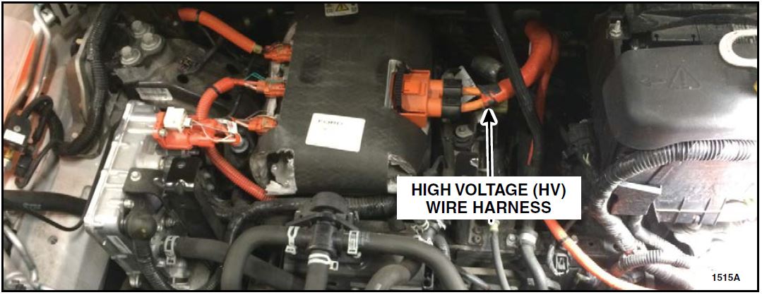
- Inspect the HV wire harness. See Figure 1a.
FIGURE 1a
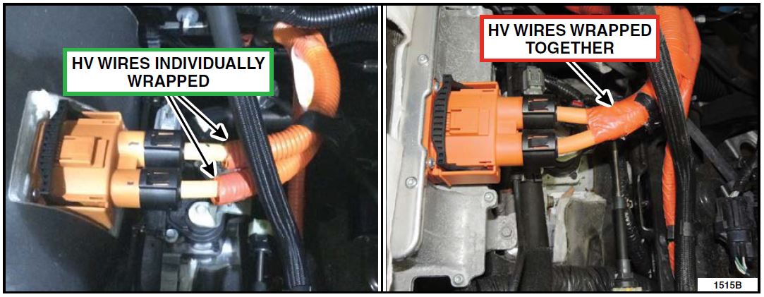
- Are the HV wires individually wrapped in convolute? See Figures 1b and 1c.
- Yes – HV wire harness update is not required. Proceed to Module Reprograming on Page 11.
- No – Proceed to Update High Voltage Wire Harness on Page 3.
FIGURE 1b FIGURE 1c
Update High Voltage Wire Harness
- Disconnect the HV battery service disconnect. Please follow the Workshop Manual (WSM) procedures in Section 414-03A.
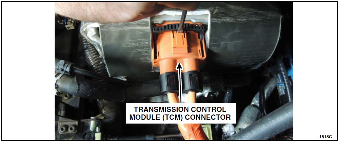
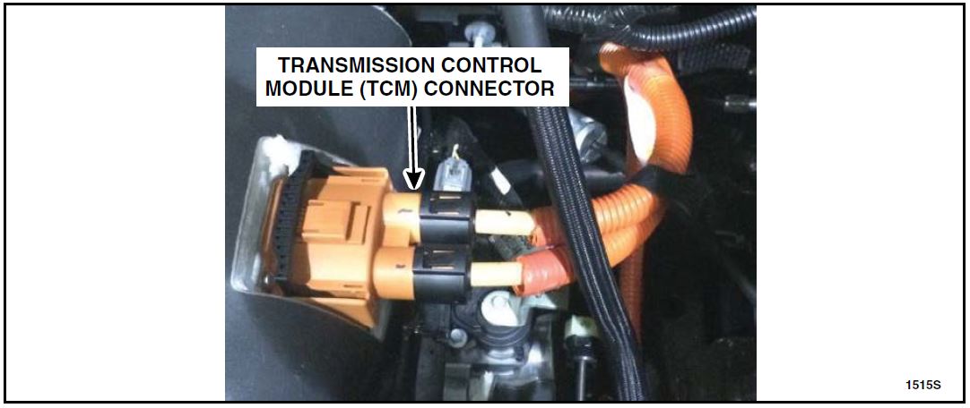
- Disconnect the Transmission Control Module (TCM) connector. See Figure 2.
FIGURE 2
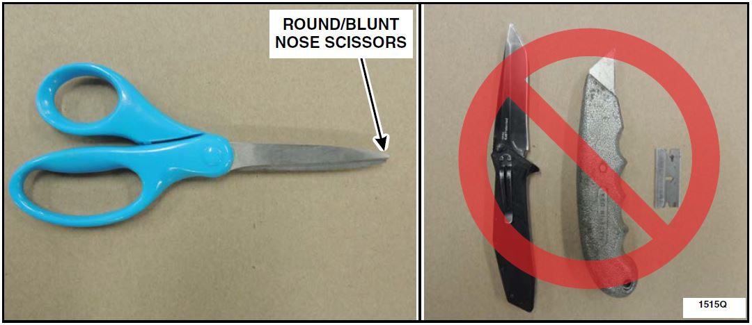
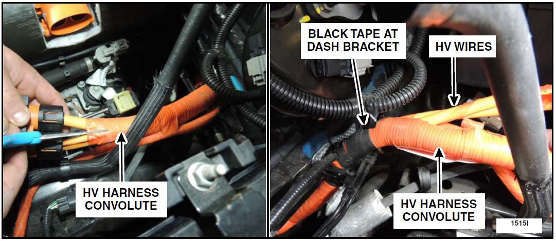
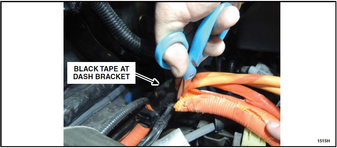
NOTE: Do not use a razor blade, utility knife or similar tool for cutting the convolute and tape. The HV wire harness can easily become damaged if round/blunt nose scissors are not used when performing this procedure. See Figure 3.
FIGURE 3
- Using a pair of round/blunt nose scissors, cut the single convolute between the wires down to the black tape at the dash bracket and discard the cut convolute. Peel back the convolute as you cut for better visibility. See Figures 4a, 4b and 4c.
FIGURE 4a FIGURE 4b
FIGURE 4c
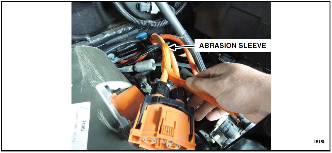
- Install the abrasion sleeves individually over each HV wire. See Figures 5 and 6.
FIGURE 5
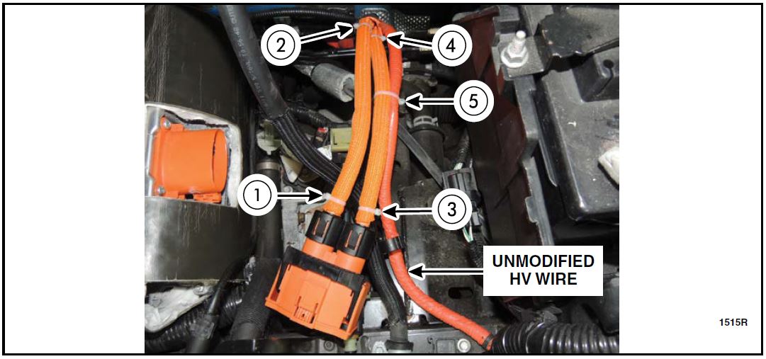
- Install the supplied tie-straps to the HV wire harness in the sequence shown. Tie-strap “5” secures the unmodified HV wire to the nearest modified HV wire. Install the tie-straps so the straps are facing away from each other. Cut off excess length of the tie-straps. See Figure 6.
NOTE: The unmodified HV wire must be secured to only one of the modified HV wires.
FIGURE 6
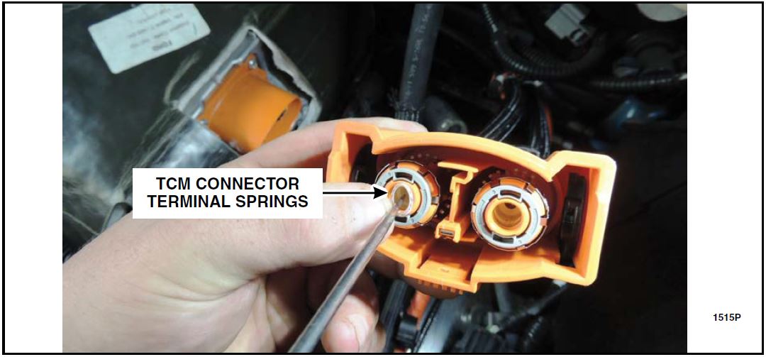
- Remove the four TCM connector terminal springs using a terminal release tool, pick or bent paper clip. Each TCM terminal contains two springs. See Figure 7.
NOTICE: Do not scratch or damage the terminal surface or spring grooves.
FIGURE 7
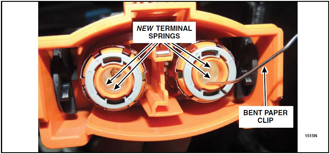
- Install the four new TCM connector terminal springs using a terminal release tool, pick or bent paper clip. Place the springs into their correct position and seat in the grooves. See Figure 8.
FIGURE 8
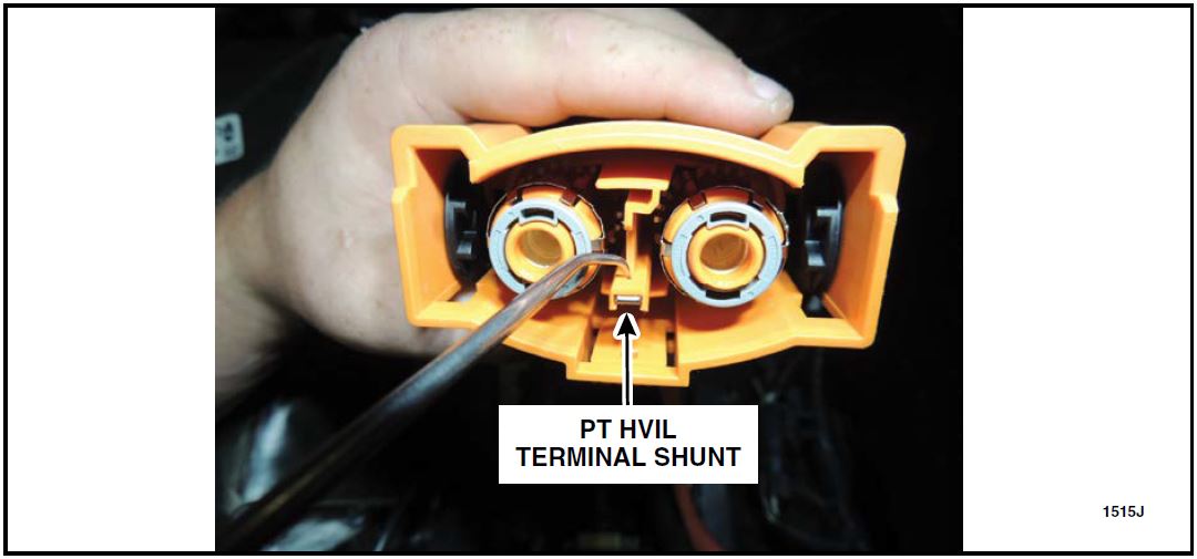
- Turn the TCM connector upside down and locate the Powertrain High Voltage Inter-Lock (PT HVIL) Terminal Shunt locking tab access hole. Using an angled pick, depress the tab while pulling the shunt out of the connector and discard the shunt. See Figure 9.
FIGURE 9
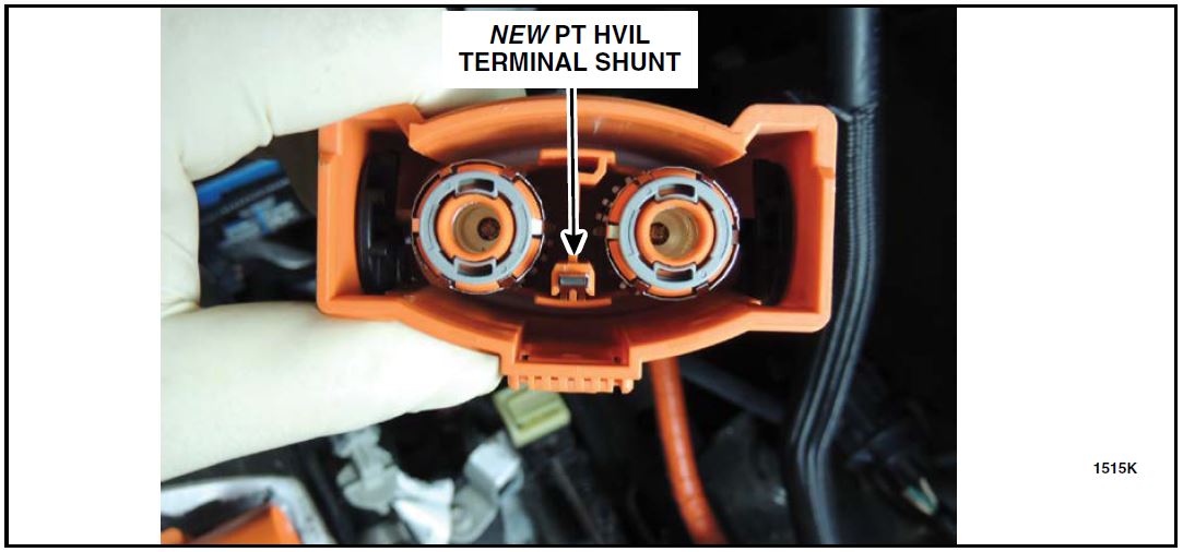
NOTICE: Use latex gloves for this portion of the repair. Be careful not to touch the gold surface of the new shunt.
NOTICE: Do not compress the new shunt when installing into the TCM connector.
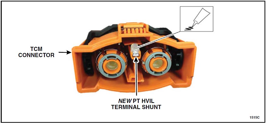
- Install the new PT HVIL Terminal Shunt by slowly sliding into the slotted opening until an audible “click” is heard and the shunt is locked in place. See Figure 10.
FIGURE 10
- Using a lint free cloth, lightly wipe all surfaces of the shunt after installation. Apply Motorcraft Electrical Grease XG-12 to the new PT HVIL Terminal Shunt. See Figure 11.
NOTE: Apply the grease to the PT HVIL Terminal Shunt only.
FIGURE 11
- Connect and disconnect the TCM connector. See Figure 2.
- Verify all components remain in the correct position. See Figures 8 and 10.
- Reconnect the TCM connector. See Figure 2.
- Install the engine cover and the two engine cover retainer pins.
- Connect the HV battery service disconnect. Please follow the WSM procedures in Section 414-03A.
- Proceed to Module Reprogramming on Page 11.
Vehicles Built On or After May 19, 2014
Clean and Apply Electrical Grease to the PT HVIL Terminal Shunt
- Disconnect the High Voltage (HV) battery service disconnect. Please follow the Workshop Manual (WSM) procedures in Section 414-03A.
- Remove the two engine cover retainer pins, then remove the engine cover.
- Disconnect the Transmission Control Module (TCM) connector. See Figure 12.
FIGURE 12
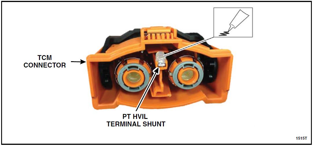
- Using a lint free cloth, lightly wipe all surfaces of the Powertrain High Voltage Inter-Lock (PT HVIL) Terminal Shunt. Apply Motorcraft Electrical Grease XG-12 to the (PT HVIL) Terminal Shunt. See Figure 13.
NOTE: Apply the grease to the PT HVIL Terminal Shunt only.
FIGURE 13
- Connect the TCM connector. See Figure 12.
- Install the engine cover and the two engine cover retainer pins.
- Connect the HV battery service disconnect. Please follow the WSM procedures in Section 414-03A.
- Proceed to Module Reprogramming on Page 11.
Module Reprogramming – All Vehicles
NOTE: Reprogram appropriate vehicle modules before performing diagnostics and clear all Diagnostic Trouble Codes (DTCs) after programming. For DTCs generated after reprogramming, follow normal diagnostic service procedures.
- Connect a battery charger to the 12V battery.
- Reprogram the Powertrain Control Module (PCM) using Integrated Diagnostic System (IDS) release 93.03 or higher.
NOTE: A coordinated reflash is required when reprogramming the PCM. When PCM reprogramming is initiated, the IDS will check for software updates on certain onboard modules (Anti-lock Brake System (ABS) module, Transmission Control Module (TCM), etc.). The IDS will automatically install updates in these modules if they are not at the latest level. If the coordinated reflash is interrupted, undesired vehicle operation may result.
NOTE: Calibration files may also be obtained at www.motorcraftservice.com.
NOTE: Follow the IDS on-screen instructions to complete the reprogramming procedure.
- Disconnect the battery charger from the 12V battery, once reprogramming has completed.
Important Information for Module Programming
NOTE: When programming or reprogramming a module, use the following basic checks to ensure programming completes without errors.
- Make sure the 12V battery is fully charged before carrying out the programming steps and connect IDS/scan tool to a power source.
- Inspect Vehicle Communication Module (VCM) and cables for any damage. Make sure scan tool connections are not interrupted during programming.
- A hardwired connection is strongly recommended.
- Turn off all unnecessary accessories (radio, heated/cooled seats, headlamps, interior lamps, HVAC system, etc.) and close doors.
- Disconnect/depower any aftermarket accessories (remote start, alarm, power inverter, CB radio, etc.).
- Follow all scan tool on-screen instructions carefully.
- Disable IDS/scan tool sleep mode, screensaver, hibernation modes.
- Create all sessions Key On Engine Off (KOEO). Starting the vehicle before creating a session will cause errors within the programming inhale process.
Recovering a module when programming has resulted in a blank module:
NEVER DELETE THE ORIGINAL SESSION!
a. Obtain the original IDS that was used when the programming error occurred during Module Reprogramming (MR) or Programmable Module Installation (PMI).
b. Disconnect the VCM from the Data Link Connector (DLC) and the IDS.
c. Reconnect the VCM to IDS and then connect to the DLC. Once reconnected, the VCM icon should appear in the corner of the IDS screen. If it does not, troubleshoot the IDS to VCM connection.
d. Locate the ORIGINAL vehicle session when programming failed. This should be the last session used in most cases. If not, use the session created on the date that the programming failed.
NOTE: If the original session is not listed in the previous session list, click the ”Recycle Bin” icon at the lower right of the previous session screen. This loads any deleted sessions and allows you to look through them. Double-click the session to restore it.
e. Once the session is loaded, the failed process should resume automatically.
f. If programming does not resume automatically, proceed to the Module Programming menu and select the previously attempted process, PMI or MR.
g. Follow all on-screen prompts/instructions.
h. The last screen on the IDS may list additional steps required to complete the programming process.
Make sure all applicable steps listed on the screen are followed in order.
January 2016
Customer Satisfaction Program 15B23
Programa de satisfacción del cliente 15B23
Mr. John Sample
123 Main Street
Anywhere, USA 12345
Your Vehicle Identification Number (VIN): 12345678901234567
At Ford Motor Company, we are committed not only to building high quality, dependable products, but also to building a community of happy, satisfied customers. To demonstrate that commitment, we are providing a no-charge Customer Satisfaction Program for your vehicle with the VIN shown above.
Why are you receiving this notice?
 “Stop Safely Now” | On your vehicle, a fault in the High Voltage wire harness may cause a “Stop Safely Now” message with a red triangle indicator to appear in the instrument cluster and the Malfunction Indicator Lamp (MIL) may also illuminate. Your vehicle will continue to function normally at speeds above 3 mph; however, you may begin to lose motive power as you bring your vehicle to a stop. If this condition occurs before your dealer visit, you can restart your vehicle by shifting it into Park, turning the vehicle off, and waiting two minutes. |
What will Ford and your dealer do? and your dealer do? | In the interest of customer satisfaction, Ford Motor Company has authorized your dealer to inspect and update the High Voltage wire harness as required and update the Powertrain Control Module (PCM) calibration free of charge (parts and labor) under the terms of this program. Motor Company has authorized your dealer to inspect and update the High Voltage wire harness as required and update the Powertrain Control Module (PCM) calibration free of charge (parts and labor) under the terms of this program.
This Customer Satisfaction Program will be in effect until December 31, 2016 regardless of mileage. Coverage is automatically transferred to subsequent owners. |
| How long will it take? | The time needed for this repair is less than one-half day. However, due to |
| service scheduling requirements, your dealer may need your vehicle for a longer period of time. In addition, your vehicle may require an inspection to determine if parts need to be ordered. | |
| What should you do? | Please call your dealer without delay and request a service date for Customer Satisfaction Program 15B23. Provide the dealer with the VIN of your vehicle. The VIN is printed near your name at the beginning of this letter.
If you do not already have a servicing dealer, you can access www.Fordowner.com for dealer addresses, maps, and driving instructions. Ford |
| Have you previously paid for this repair? | If you have previously paid for a repair that addresses the issue described in this letter, you still need to have this service action performed to ensure the correct parts and procedures were used.
If the previously paid for repair was performed before the date of this letter, you may be eligible for a refund. Refunds will only be provided for service related to Powertrain Control Module (PCM) Diagnostic Trouble Code (DTC) P0A0A-01 when the High Voltage Wire Harness was determined to be causing the concern. To verify eligibility and expedite reimbursement, give your paid original receipt to your dealer before August 1, 2016. |
| What if you no longer own this vehicle? | If you no longer own this vehicle, and have an address for the current owner, please forward this letter to the new owner.
You received this notice because our records, which are based primarily on state registration and title data, indicate that you are the current owner. |
| Can we assist you further? | If you have difficulties getting your vehicle repaired promptly and without charge, please contact your dealership’s Service Manager for assistance.
RETAIL OWNERS: If you still have concerns, please contact the Ford If you wish to contact us through the Internet, our address is: www.Fordowner.com. Si necesita ayuda o tiene alguna pregunta, por favor llame al Centro de Relación con Clientes al 1-866-436-7332 y presione 2 para Español. FLEET OWNERS: If you still have concerns, please contact the Fleet Customer Information Center at 1-800-34-FLEET, Option #3 and one of our representatives will be happy to assist you. Representatives are available Monday through Friday: 8:00AM – 8:00PM (Eastern Time). Or you may contact us through the Internet at www.fleet.ford.com. |
Thank you for your attention to this important matter.
Ford Customer Service Division
 Loading...
 Loading...
 Loading...
Service Information & Reprogramming
Software necessary to program electronic modules to the latest calibration level, perform module initialization (PATS), and set Programmable Parameters on Ford , Lincoln
 and Mercury
 vehicles.
Ford Module Programming (FMP) is a software application that allows subscribers to program electronic modules on Ford , Lincoln
 and Mercury
 vehicles. It can be used for:
- Reprogramming emission-related (OBDII) modules on some vehicles manufactured in 1995 and all vehicles manufactured from 1996 to the present
- Reprogramming or reconfiguring non-emission-related modules on many vehicles (UBP and MS-CAN not supported)
In addition, module initialization (PATS) functions such as Keycode Erase/Reprogram and PCM Parameter Reset can be done using this application.
J2534 Device ![]()
![]() using Ford Module Programming (FMP) can Reprogram and Configure most Modules.
using Ford Module Programming (FMP) can Reprogram and Configure most Modules.
Latest Calibration Information
Module Build Data (As-Built)
Use VIN to obtain As-Built data
