| “This site contains affiliate links for which OEMDTC may be compensated” |
| 6.7L ENGINE – NO CRANK/NO START AND/OR BATTERY DRAIN – EQUIPPED WITH DUAL FUEL TANKS – BUILT ON OR BEFORE 5/5/2014 |
FORD : : | 2015 F-450, F-550 |
2015 F- Super Duty 450/550 vehicles equipped with a 6.7L diesel engine, dual fuel tanks and built on or before 5/5/2014 may exhibit a discharged battery and a no crank/no start condition when the rear dual fuel tank selector switch is left in the on position.
These conditions may be attributed to low impedance in the dual tank switch system.
SERVICE PROCEDURE
- Disconnect the batteries.
- Recharge batteries as required.
- Remove the passenger right front cowl side trim panel.
- Remove G302 terminal screw and position aside.
- Disconnect connector C2280B from the body control module (BCM).
- Identify the gray/yellow (GY/YE) wire from relay kit. Strip 33 mm (1.25”) of insulation from the end of the wire.
- Identify the wire pin terminal from the wiring kit parts list and strip 33 mm (1.25”) of insulation from the end of the wire.
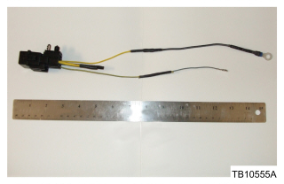
- Connect the relay kit GY/YE wire and pin terminal together. (Figure 1)
- For all connections use only the solder splicing method and protect the connections with heat shrink tubing. The heat shrink tubing supplied in the kit contains hot melt glue that creates a waterproof and airtight connection. Make sure the heat shrink tubing covers all exposed wires plus at least half inch at both ends. Refer to WD, Section 5-1.
- In the relay circuits kit, the yellow/green (YE/GN) and gray/blue (GY/BU) wires are not used. Heat shrink the unused circuits supplied in the relay kit. (Figure 1)
Figure 1
- Identify the YE wire from the relay kit. Strip 33 mm (1.25”) of insulation from the end of the wire.
- Identify black (BK) ground eyelet pin terminal 105460. Strip 33 mm (1.25”) of insulation away from ground wiring terminal.
- Connect relay kit YE wire and ground pin terminal 105460 together. (Figure 1)
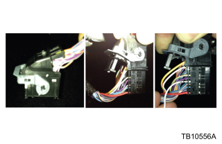
- On connector C2280B, slide back black cover of the connector and insert the GY/YE spliced pin terminal, from Step 7, into empty cavity pin 5 of connector C2280B. Secure the pin in the connector and close the cover of connector C2280B. Refer to WD, 13-1. (Figure 2)
Figure 2
- Reconnect C2280B to BCM.
- Reassemble G302 with relay kit ground eyelet and tighten screw to 12 Nm (106 lb-in).
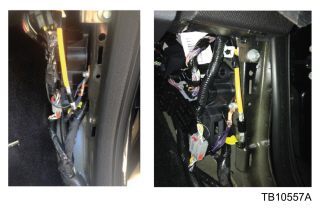
- Secure the relay kit in a vertical position to the existing radio antenna wiring harness tab. (Figure 3)
Figure 3
- Reinstall the passenger right front cowl side trim panel.
- Reconnect the batteries.
| AU5Z-14N089-FA | Relay Kit |
| DU2Z-14474-AA | Wire Terminal Kit |


