| “This site contains affiliate links for which OEMDTC may be compensated” |
| TSB 17-0013 | 6.7L – DUAL FUEL TANKS – HYDRAULIC BRAKES – BUZZ NOISE FROM TRANSMISSION AND/OR DISCHARGED BATTERIES – BUILT ON OR BEFORE 30-NOV-2016 |
| Publication Date: February 10, 2017 | |
FORD : : | 2016-2017 F-650, F-750 |
ISSUE:
Some 2016-2017 F-650/750 vehicles equipped with a 6.7L engine, dual fuel tanks, hydraulic brakes and built on or before 30-Nov-2016 may exhibit discharged batteries, with or without a slow/no crank condition, when the dual fuel tank selector switch is set to the right hand side fuel tank. The vehicle may also exhibit a buzzing noise from the transmission when the key is off and the dual fuel tank selector switch is set to the right hand side fuel tank. This may be due to the dual tank selector switch allowing an instrument panel cluster (IPC) sense voltage to back feed into the key power fuse panel circuits causing the transmission control module (TCM) to remain in the key on mode when the key is off.
ACTION:
Follow the Service Procedure steps to correct the condition.
SERVICE PROCEDURE
Adding the electrical load of a relay coil to the fuse panel circuit will draw the IPC sense voltage low enough to allow the TCM to properly transition to the key off mode.
- Cut the yellow/green (YE/GN) wire and both gray/blue (GY/BU) wires of the new relay kit to approximately 75 mm (3 inch) and heat shrink the ends, these circuits are not used. (Figure 1)
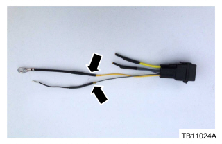
Figure 1 – 17-0013 - Using the solder splicing method, connect the gray/yellow (GY/YE) wire from the relay kit and one pin terminal from the wire-terminal kit together. The pin terminal can be cut to create a total wire length of approximately 250 mm (10 inch). Refer to Wiring diagram (WD), Section 5-5. (Figure 1)
- Connect the yellow (YE) wire from the relay kit and the ground eyelet pin terminal 105460 together using the solder splicing method. Refer to WD, Section 5-5. (Figure 1)
- Disconnect the batteries. Refer to Workshop Manual (WSM), Section 414-01.
- Charge batteries as required. Refer to WSM, Section 414-01.
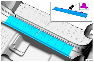
- Remove the right front door scuff plate. (Figure 2)

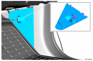
Figure 2 – 17-0013 - Remove the body control module (BCM) fuse access cover. (Figure 3)

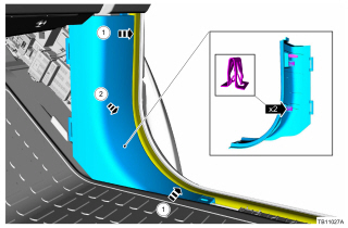
Figure 3 – 17-0013 - Remove the right side lower cowl trim panel. (Figure 4)

Figure 4 – 17-0013 - Disconnect C2280B from the BCM. Refer to WD, Section 11-4.
- Cut the strain relief wire tie strap from C2280B, release the connector cover tab and slide back the connector cover.
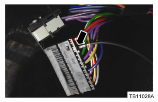
- Insert the terminal that was spliced to the relay kit into empty cavity 3 of C2280B. Secure the pin in the connector, close the cover and install a new strain relief wire tie strap. (Figure 5)

Figure 5 – 17-0013 - Reconnect C2280B to the BCM.
- Remove G302 terminal screw, install the ground eyelet from the relay kit and secure with a screw. Tighten the screw to 12 Nm (106 lb-in). Refer to Wiring Diagram (WD), Section 152-1.
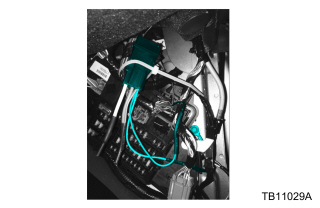
- Using a new wire tie strap, secure the relay kit in a vertical position to the vehicle’s harness. (Figure 6)

Figure 6 – 17-0013 - Reinstall the right side lower cowl trim panel, BCM fuse access cover and right front door scuff plate. (Figures 2 – 4)
- Reconnect the batteries. Refer to WSM, Section 414-01.
| Obtain Locally |
| Part Description |
| 200 mm (8 inch) Tie Strap |
| AU5Z-14N089-FA | Relay Kit |
| DU2Z-14474-AA | Wire – Terminal Kit |
| OPERATION | DESCRIPTION | TIME |
| 170013A | 2016-2017 F650/750: Modify The Relay Assembly And Install Following The Service Procedure (Do Not Use With Any Other Labor Operations) | 0.8 Hr. |
WARRANTY STATUS
Eligible Under Provisions Of New Vehicle Limited Warranty Coverage And Emissions Warranty Coverage.
Warranty/ESP coverage limits/policies/prior approvals are not altered by a TSB. Warranty/ESP coverage limits are determined by the identified causal part and verified using the OASIS part coverage tool.
DEALER CODING
| BASIC PART NO. | CONDITION CODE |
| 12A581 | 39 |
 Loading...


![Discharged Batteries, with or without a Slow/No Crank Condition - Buzzing Noise from Transmission - 2016-2017 Ford F-650, F-750 15 True MODS 1 Pack 5-Pin 12V Bosch Style Waterproof Relay Kit [Harness Socket] [12 AWG Hot Wires] [SPDT] [30/40 Amp] 12 Volt Automotive Marine Relays for Boats Auto Fan Cars](https://m.media-amazon.com/images/I/41kuW9VnZxL._SL75_.jpg)
