| “This site contains affiliate links for which OEMDTC may be compensated” |
NHTSA ID Number: 10149785
Manufacturer Communication Number: 17B25-S5
Summary
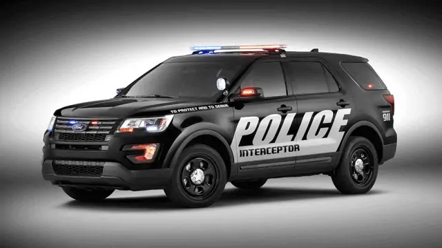
Certain 2013-2017 Model Year Police Interceptor Utility Vehicles – Exhaust Odor and Carbon Monoxide Complaints
5 Affected Products
Vehicles
November 13, 2017
TO: All U.S. Ford and Lincoln
 Dealers
SUBJECT: NEW VEHICLE DEMONSTRATION / DELIVERY HOLD –
Customer Satisfaction Program 17B25 – Supplement #5
Certain 2013-2017 Model Year Police Interceptor Utility Vehicles
Exhaust Odor and Carbon Monoxide Complaints
REF: Customer Satisfaction Program 17B25 – Supplement #4
Dated: October 25, 2017
Customer Satisfaction Program 17N03
Dated: October 25, 2017
REASON FOR THIS SUPPLEMENT
- Program Terms: The expiration date for this program has been extended through March 31, 2019.
PROGRAM TERMS
This program will be in effect through March 31, 2019. There is no mileage limit for this program.
URGENCY / EXPIRATION DATE
This Customer Satisfaction Program has an expiration date of March 31, 2019, to encourage dealers and customers to have this service performed as soon as possible.
We recommend dealers utilize their FSA VIN Lists name and address (available by October 6, 2017) to contact customers with affected vehicles.
AFFECTED VEHICLES
| Vehicle | Model Year | Assembly Plant | Build Dates |
| Police Interceptor Utility | 2013-2017 | Chicago | August 25, 2011 through Job Last 2017MY |
Affected vehicles built up to October 6, 2017 are identified in OASIS and FSA VIN Lists. Additional vehicles will be periodically added to this program until production ends for the 2017 model year.
REASON FOR THIS PROGRAM
When an up-fitter installs customized emergency lighting, radios and other equipment, they may damage vehicle sealing systems and/or drill holes into the rear of the vehicle. This creates an opening where exhaust could enter the cabin if the sealing system is not properly repaired and holes are not properly sealed. In addition, this customer satisfaction program provides unique upgrades to Police Interceptor Utility vehicles to address customer concerns with carbon monoxide.
SEE VIDEO & NEWS RELEASE: Unsealed Holes Contribute to Exhaust Concerns in Police Interceptor Utility
SERVICE ACTION
Click Here to view a video demonstration of key inspection and repair procedures.
For Police Interceptor Utility vehicles equipped, or formerly equipped with police/aftermarket up-fitter modifications, dealers are to inspect the rear of the vehicle and repair damage to body seals, grommets and liftgate spoiler sealing systems, seal the liftgate interior trim panel, install new muffler tips, seal certain body plugs in the floor pan, reprogram the Climate Control (HVAC) module, and check the Powertrain Control Module (PCM) for diagnostic trouble code (DTC) P0420 and/or P0430 following the technical instructions.
For Police Interceptor Utility vehicles not equipped with police/aftermarket up-fitter modifications, dealers are to install new muffler tips, seal certain body plugs in the floor pan, reprogram the HVAC module, and check the PCM for DTC P0420 and/or P0430 following the technical instructions.
This service must be performed on all affected vehicles at no charge to the vehicle owner.
Aftermarket lighting and/or equipment mounted to the liftgate spoiler can compromise vehicle sealing. Ford can only ensure proper sealing of the spoiler when aftermarket lighting and/or equipment are removed and the spoiler is resealed.
Before removing aftermarket lighting and/or equipment from the spoiler, contact the customer to obtain their approval to conduct this part of the service. If a customer elects to keep aftermarket lighting and/or equipment on the spoiler, proceed with the following actions:
- Document on the repair order that the service to reseal the spoiler and remove the aftermarket lighting and/or equipment from the spoiler was declined
- Print and provide the customer with the Customer Information Form – Liftgate Spoiler – Aftermarket Lighting and/or Equipment (Attachment V)
- Complete all other steps of this field service action
- Release the vehicle to the customer
OWNER NOTIFICATION MAILING SCHEDULE
Owner letters were mailed the week of September 25, 2017. Owners will be notified again the week of October 8, 2018, to inform them of the program extension. Dealers should repair any affected vehicles that arrive at their dealerships, whether or not the customer has received a letter.
New! ATTACHMENTS
Attachment I: Administrative Information
Attachment II: Labor Allowances and Parts Ordering Information
Attachment III: Technical Information
Attachment IV: Dealer Q & A
Attachment V: Customer Information Form – Liftgate Spoiler – Aftermarket Lighting and/or Equipment
Attachment VI: 6 Important Facts About Carbon Monoxide and Police Vehicles
Owner Notification Letter
QUESTIONS & ASSISTANCE
For questions and assistance, contact the Special Service Support Center (SSSC) via the SSSC Web Contact Site. The SSSC Web Contact Site can be accessed through the Professional Technician Society (PTS) website using the SSSC link listed at the bottom of the OASIS VIN report screen or listed under the SSSC tab.
Sincerely,
Michael A. Berardi
ATTACHMENT I
NEW VEHICLE DEMONSTRATION / DELIVERY HOLD –
Customer Satisfaction Program 17B25 – Supplement #5
Certain 2013-2017 Model Year Police Interceptor Utility Vehicles
Exhaust Odor and Carbon Monoxide Complaints
OASIS ACTIVATION
OASIS was activated on July 28, 2017, for vehicles built up to July 19, 2017, and has been updated to include affected vehicles up to September 12, 2017. Additional 2017MY vehicles will be periodically added to this program until production ends for the model year.
FSA VIN LISTS ACTIVATION
FSA VIN Lists will be available through https://web.fsavinlists.dealerconnection.com on September 13, 2017. Owner names and addresses will be available by October 6, 2017.
NOTE: Your FSA VIN Lists may contain owner names and addresses obtained from motor vehicle registration records. The use of such motor vehicle registration data for any purpose other than in connection with this program is a violation of law in several states, provinces, and countries. Accordingly, you must limit the use of this listing to the follow-up necessary to complete this service action.
SOLD VEHICLES
- Owners of affected vehicles will be directed to dealers for repairs.
- Immediately contact any of your affected customers whose vehicles are not on your VIN list but are identified in OASIS. Give the customer a copy of the Owner Notification Letter (when available) and schedule a service date.
- Correct other affected vehicles identified in OASIS which are brought to your dealership.
- Dealers are to prioritize repairs of customer vehicles over repairs of new and used vehicle inventory.
STOCK VEHICLES
- Correct all affected units in your new vehicle inventory before delivery.
- Use OASIS to identify any affected vehicles in your used vehicle inventory.
TITLE BRANDED / SALVAGED VEHICLES
Affected title branded and salvaged vehicles are eligible for this service action.
ADDITIONAL REPAIR (LABOR TIME AND/OR PARTS)
Additional repairs identified as necessary to complete the FSA should be managed as follows:
- For vehicles within new vehicle bumper-to-bumper warranty coverage, follow existing warranty and policy guidelines for related damage claims. No SSSC approval is required for these vehicles:
- Ford
 vehicles – 3 years or 36,000 miles
- Ford
- For vehicles outside new vehicle bumper-to-bumper warranty coverage, submit an Approval Request to the SSSC Web Contact Site prior to completing the repair.
OWNER REFUNDS
- Ford
 Motor Company is offering a refund for owner-paid repairs covered by this program if the repair was performed before the date of the Owner Notification Letter. This refund offer expires March 31, 2018.
 - Refunds will only be provided for the cost associated with the inspection and repair of vehicles with exhaust odor and carbon monoxide complaints using TSB 16-0166 or 17-0044, and exhaust catalyst replacement for DTC P0420 and/or P0430.
RENTAL VEHICLES
Rental vehicles are not approved for this program.
CLAIMS PREPARATION AND SUBMISSION
- Enter claims using Direct Warranty Entry (DWE) or One Warranty Solution (OWS).
- DWE: refer to ACESII manual for claims preparation and submission information.
- OWS: when entering claims in DMS software, select claim type 31: Field Service Action. The FSA number 17B25 is the sub code.
- Additional labor and/or parts must be claimed as related damage on a separate repair line from the FSA.
- Submit refunds on a separate repair line.
- Program Code: 17B25 – Misc. Expense: ADMIN
- Misc. Expense: REFUND – Misc. Expense: 0.2 Hrs.
- Multiple refunds should be submitted on one repair line and the invoice details for each repair should be detailed in the comments section of the claim.
- Sublet repairs must be claimed using labor operations listed in this bulletin. Do not claim as Outside Labor (OSL). Refer to Warranty & Policy Manual for additional information.
- Provision for Locally Obtained Supplies: Includes automotive body seam sealer, anti-corrosion coating, Loctite 414 or 495, and High Temperature Paint.
- Program Code: 17B25 o Misc Expense: OTHER o Amount: Actual cost up to $25.00
- PROGRAM TERMS: This program will be in effect through March 31, 2019. There is no mileage limit for this program.
ATTACHMENT II
NEW VEHICLE DEMONSTRATION / DELIVERY HOLD –
Customer Satisfaction Program 17B25 – Supplement #5
Certain 2013-2017 Model Year Police Interceptor Utility Vehicles
Exhaust Odor and Carbon Monoxide Complaints
LABOR ALLOWANCES – All Vehicles (Use One)
| Description | Labor Operation | Labor Time |
In-stock/unsold/undelivered vehicle (Modified or Not Modified)
| 17B25B repairs before September 21, 2017 | 1.0 Hour |
| 17B25BB repairs on/after September 21, 2017 | 1.1 Hours | |
Customer/sold vehicle
| 17B25C repairs before September 21, 2017 | 1.1 Hours |
| 17B25CC repairs on/after September 21, 2017 | 1.2 Hours |
LABOR ALLOWANCES – As Required
| Description | Labor Operation | Labor Time | |
|---|---|---|---|
| Additional time to allow for subletting a portion of the repair, such as installing muffler tips (up to 0.3 Hours) | Use in combination with 17B25B/BB or 17B25C/CC | MT17B25 | Up to 1.3 Hours |
| Seal grommets, body plugs and holes with body seam sealer and mastic patch as required (up to 1.0 Hours) | Use in combination with 17B25C or 17B25CC only | ||
| Remove liftgate spoiler and replace seals and fasteners | 17B25D | 0.4 Hours | |
| Replace Air Extractor (one or both) | 17B25E | 1.0 Hours | |
| Replace Exhaust Catalyst – 3.7L Right Hand | 17B25F | 1.5 Hours | |
| Replace Exhaust Catalyst – 3.7L Left Hand | 17B25G | 1.0 Hours | |
| Replace Exhaust Catalysts – 3.7L Both | 17B25H | 2.1 Hours | |
| Replace Exhaust Catalyst – 3.5L Right | 17B25J | 0.7 Hours | |
| Replace Exhaust Catalyst – 3.5L Left Hand | 17B25K | 0.7 Hours | |
| Replace Exhaust Catalysts – 3.5L Both | 17B25L | 1.2 Hours | |
NOTE: To obtain reimbursement for subletting a portion of the repair on claims paid before November 13, 2017, submit an on-line appeal by December 15, 2017. Refer to the Warranty & Policy Manual for additional information.
PARTS REQUIREMENTS / ORDERING INFORMATION
| Description | Order Quantity | Claim Quantity | Part Number |
| Liftgate Trim Panel Sealing Kit | 1 | 1 | BB5Z-7841617-A |
| Muffler Tips – 3.7L Engine (All – 95% of program population) | 2 | 2 | DB5Z-5202-A |
| Muffler Tips – 3.5L GTDI Engine (2016-2017MY – 4% of program population) | 2 | 2 | FB5Z-5202-A |
| Muffler Tips – 3.5L GTDI Engine (2013-2015MY – 1% of program population) | 2 | 2 | FB5Z-5202-B |
| Foil-Backed Mastic Patch (for underbody plugs) | 2 | 2 | CK4Z-13014-B |
| Motorcraft Instant Gel Adhesive (or equivalent, including but not limited to Loctite 414 or 495) | As Required | MISC.
OTHER | TA-19-C |
| Motorcraft Seam Sealer (or equivalent, including but not limited to Lord Fusor 802HD, 804HD, 805HD or 806HD and 3M 08367 or 08405) | TA-2-B | ||
| Motorcraft Anti-Corrosion Coating (or equivalent) | PM-13-A | ||
| High-Temperature Paint | Obtain Locally | ||
| Liftgate Drain Valve | As Required | 4M8Z-54280B62-A | |
| Foil-Backed Mastic Patch (general sealing repairs) | As Required | 4L3Z-18203A16-AA | |
| Air Extractor | As Required | BB5Z-61280B62-B | |
| Liftgate Weather Seal (search by application) | As Required | – 78404A06 – | |
| Exhaust Catalyst (search by application) | As Required | Refer to Catalog | |
| Exhaust Fasteners and Gaskets (search by application) | As Required | Refer to Catalog | |
| Liftgate Spoiler Sealing Kit | As Required | HB5Z-78442K03-A | |
The DOR/COR number for this program is 51095.
Order your parts requirements through normal order processing channels. To guarantee the shortest delivery time, an emergency order for parts must be placed.
DEALER PRICE
For latest prices, refer to DOES II.
PARTS RETENTION AND RETURN
Follow the provisions of the Warranty and Policy Manual, Section 1 – WARRANTY PARTS RETENTION AND RETURN POLICIES.
EXCESS STOCK RETURN
Excess stock returned for credit must have been purchased from Ford Customer Service Division in accordance with Policy Procedure Bulletin 4000.
ATTACHMENT III
CERTAIN 2013-2017 MODEL YEAR POLICE INTERCEPTOR UTILITY VEHICLES — EXHAUST ODOR AND CARBON MONOXIDE COMPLAINTS
OVERVIEW
When an up-fitter installs customized emergency lighting, radios and other equipment, they may damage vehicle sealing systems and/or drill holes into the rear of the vehicle. This creates an opening where exhaust could enter the cabin if the sealing system is not properly repaired and holes are not properly sealed. This procedure provides information to identify and repair vehicle-sealing concerns that have been caused by these installations. Be aware that this technical information does not capture all possible sealing concerns caused by non-Ford equipment installations due to the variability that exists with after market equipment and installation practices. Dealer technicians should thoroughly inspect vehicles and correct all potential leak paths caused by after market up-fitter equipment using robust sealing methods.
Before removing aftermarket lighting and/or equipment from the liftgate spoiler, verify that Service Department Management obtained customer approval to conduct that part of the service customer elected to keep aftermarket lighting and/or equipment on the spoiler, proceed with the following actions:
- Complete all other steps of this field service action EXCEPT the Liftgate Spoiler Sealing
- Document on the repair order that the service to reseal the spoiler and remove the aftermarket lighting and/or equipment from the spoiler was declined.
- Print and provide the customer with the Customer Information Form – Liftgate Spoiler – Aftermarket Lighting and/or Equipment (Attachment V).
- Release the vehicle to the customer.
SERVICE PROCEDURE
NOTE: To view a video demonstration of key inspection and repair procedures, click the video icon.
- Inspect the rear half of the vehicle for police or aftermarket up-fitter equipment such as: interior or exterior lighting, radio/audio/video equipment, or up-fitter wiring that crosses from the interior to the exterior of the vehicle (inspect liftgate opening).
NOTE: Roof-mounted antennas, lights and other equipment that has been properly sealed for water intrusion will not allow exhaust odor to enter the vehicle. If the vehicle has roof-mounted equipment present, and there is no evidence of water leaks in the vehicle, no further inspection or repairs are necessary for that equipment.
NOTE: It is not necessary to inspect police or aftermarket up-fitter equipment installed in the front half of the vehicle.
- Has the vehicle been modified with aftermarket equipment as described?
- No – Begin procedure at Liftgate Trim Panel Sealing on Page 12
- Yes – Proceed to the Modified Vehicle Inspection and Sealing.
Modified Vehicle Inspection and Sealing
Air Extractor Replacement Recommended Tool List:
| 1/4″ Drive Ratchet (Power Tool & Hand Tool) |
| 1/4″ Drive Torque Wrench |
| 1/4″ Drive Extension (6 in 152 mm) |
| 1/4″ Drive 5.5mm Shallow Socket |
| 1/4″ Drive 8mm Shallow Socket |
| Trim Tool |
| Pocket Screwdriver |
| Phillips Screwdriver |
- With the vehicle in NEUTRAL, position it on a hoist. Please follow the Workshop Manual (WSM) procedures in Section 100-02.
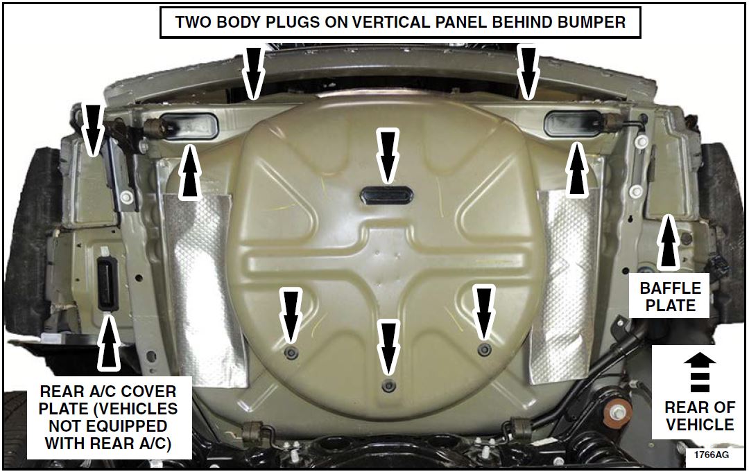
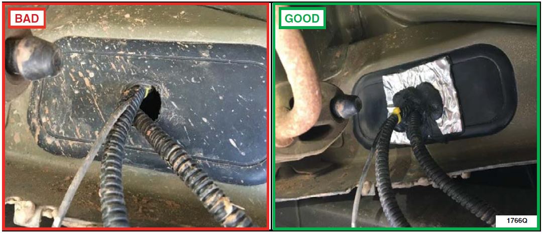
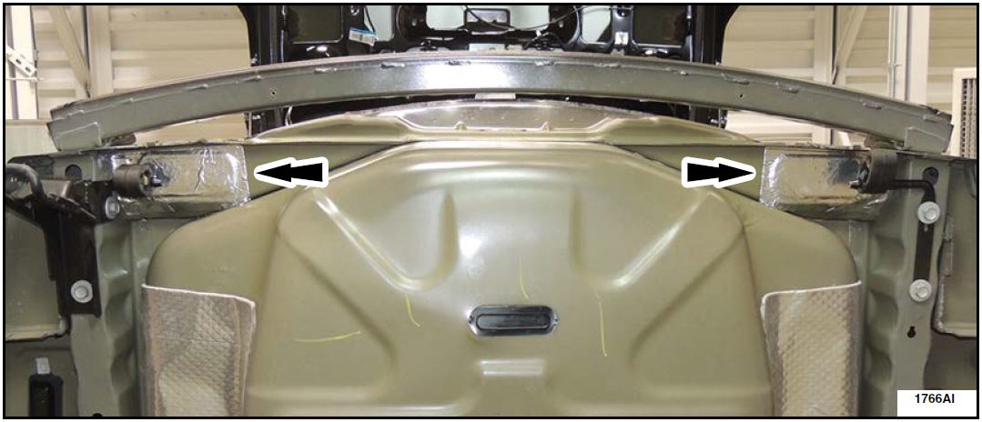
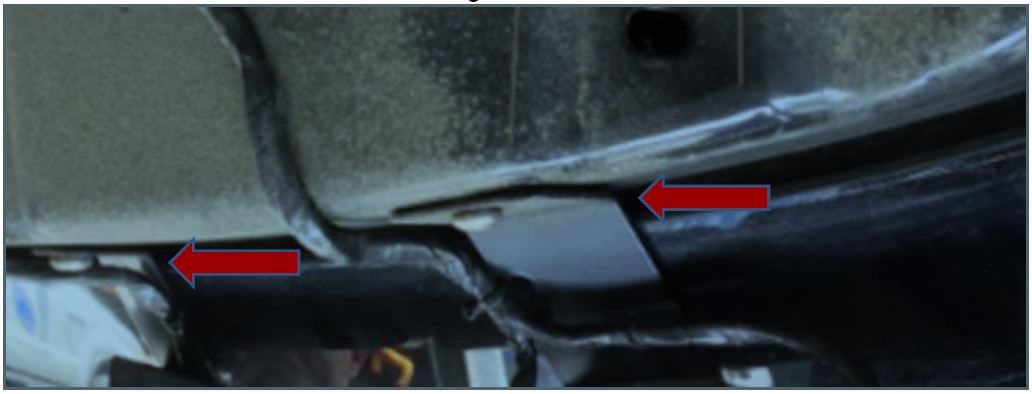
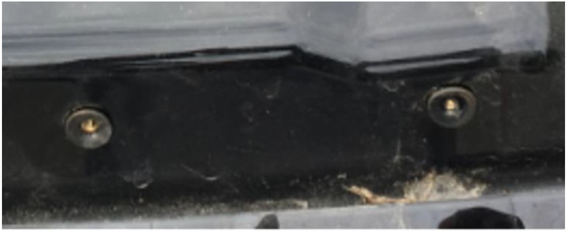
- Inspect the rear underbody for damaged or missing body plugs, punctured/damaged floor pan sheet metal and baffle plates, damaged wiring harness grommets, aftermarket fasteners, and pass throughs (holes) created for aftermarket wiring/equipment. See Figures 1, 2a and 2b.
- Seal all aftermarket wiring and equipment pass throughs using Motorcraft TA-2 seam sealer or equivalent, and Foil-Backed Mastic Patch as needed.
NOTE: Do not use silicones, RTVs or caulks during this repair
FIGURE 1
FIGURE 2a FIGURE 2b
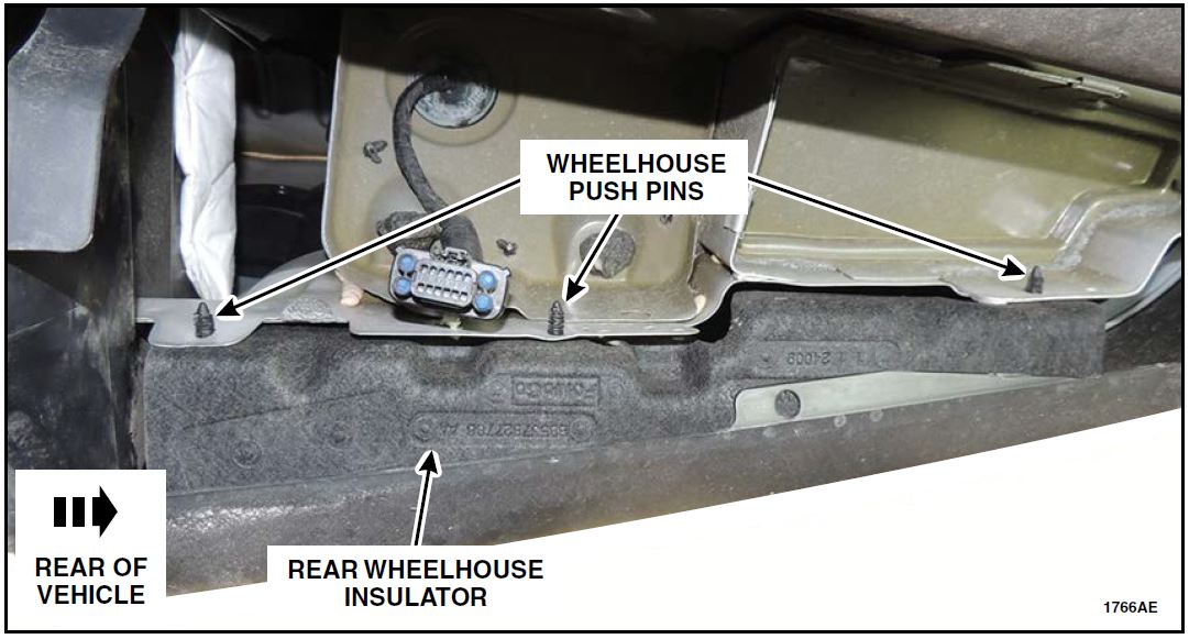
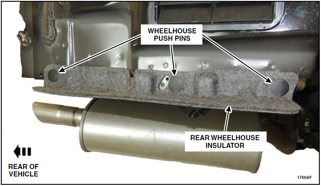
- Remove the three push-pins securing the LH and RH rear wheelhouse insulators, and remove the insulators. See Figure 3.
FIGURE 3
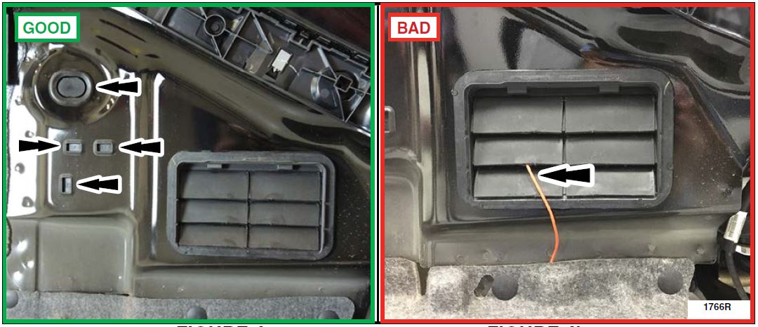
- Using a telescoping mirror and flashlight, inspect the 4 body plugs and air extractor through the wheelhouse openings on each side of the vehicle to determine if aftermarket wiring has been routed through these components. Reroute aftermarket wiring as needed. See Figures 4a and 4b.
- Replace body plugs or air extractors if any damage is present. Rear bumper cover removal is required to replace the air extractor. Please follow the WSM procedures in Section 501-19.
FIGURE 4a FIGURE 4b
- Reinstall the wheelhouse insulators. The wheelhouse push pins can be reinstalled by removing the lower inner fender well fasteners to gain access to the fasteners. See Figure 5.
FIGURE 5
- Remove the LH and RH rear tail lamp assemblies. Please follow the WSM procedures in Section 417-01.
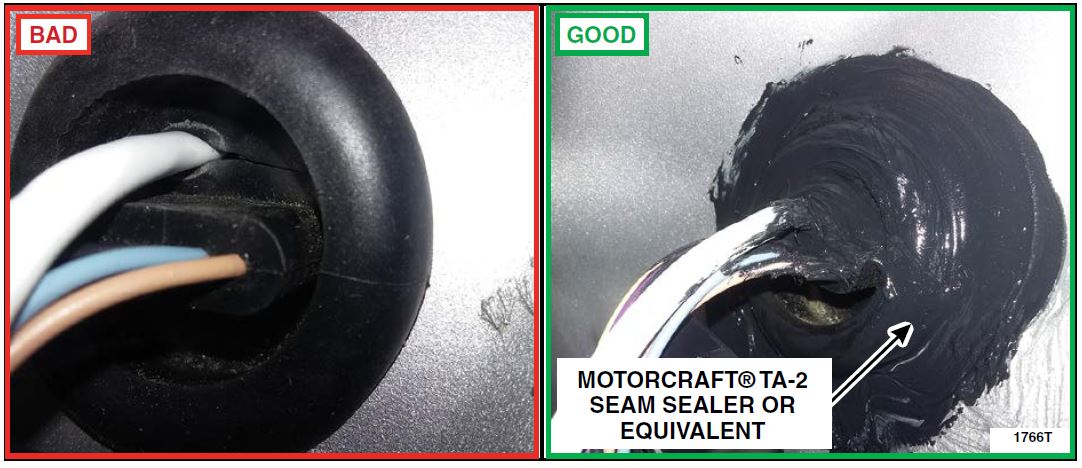
- Inspect the sheet metal, wiring harness grommets and factory equipped pass throughs for damage or holes created when installing aftermarket wiring and equipment. See Figure 6a. Seal all holes in the sheet metal and wiring harness grommets with Motorcraft TA-2 seam sealer or equivalent.
See Figure 6b.
FIGURE 6a FIGURE 6b
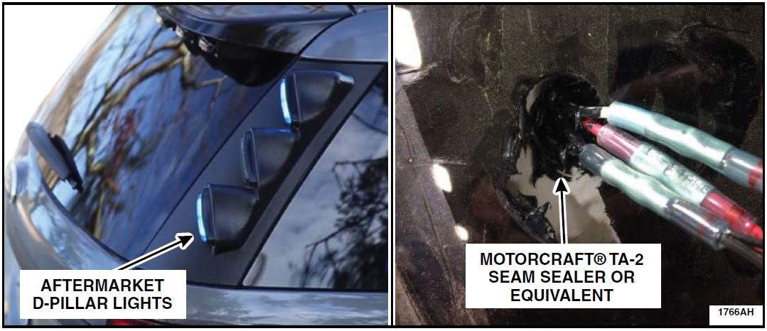
- For vehicles equipped with aftermarket lights on the D-pillars, seal all holes in the sheet metal and
wiring harness grommets used as wiring pass throughs with Motorcraft TA-2 seam sealer or
equivalent. See Figures 7a and 7b.
FIGURE 7a FIGURE 7b
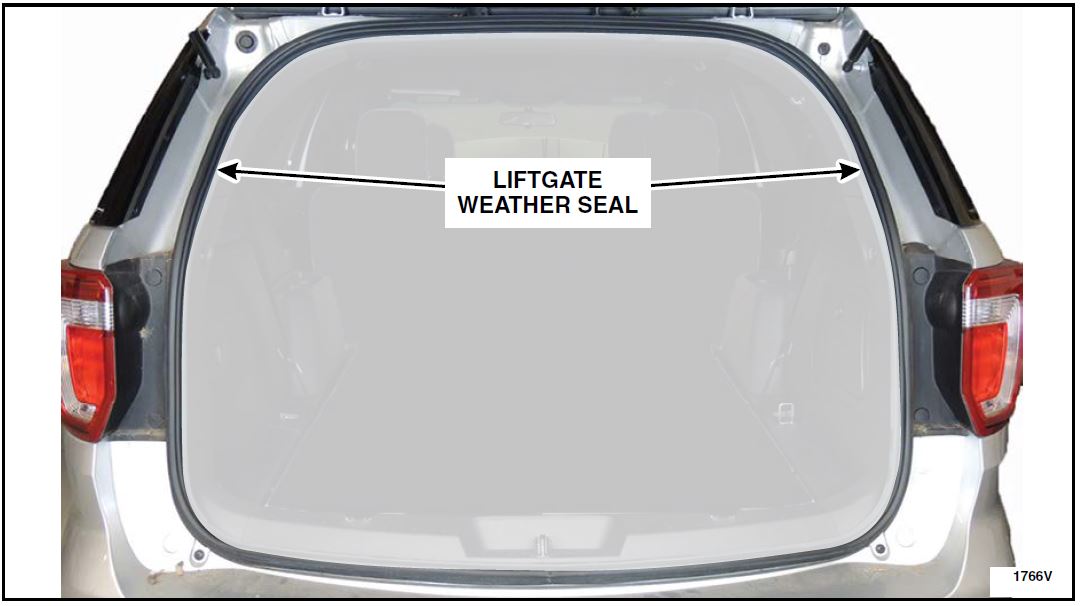
- Inspect the liftgate weather seal for damage and proper fitment to the vehicle. Replace the liftgate weatherseal if required. See Figure 8.
FIGURE 8
- Reinstall the LH and RH rear lamp assemblies. Please follow the WSM procedures in Section 417-01.
NOTE: When installing the rear lamp assemblies, ensure the liftgate weather seal is not disturbed and remains in the correct position.
Liftgate Spoiler Inspection
NOTE: Aftermarket lighting and/or equipment mounted to the liftgate spoiler can compromise vehicle sealing and create a leak path for exhaust to enter the vehicle. Ford recommends removal of any aftermarket lighting and/or equipment mounted to the spoiler to prevent a potential path for exhaust to enter the vehicle. Any removed equipment must be returned to the customer.
NOTE: If the customer declines to allow removal of aftermarket lighting and/or equipment from the liftgate spoiler, have the customer sign a copy of the Customer Release Form – Liftgate Spoiler Aftermarket Lighting and/or Equipment (See Attachment V). Retain the signed document in your service records.
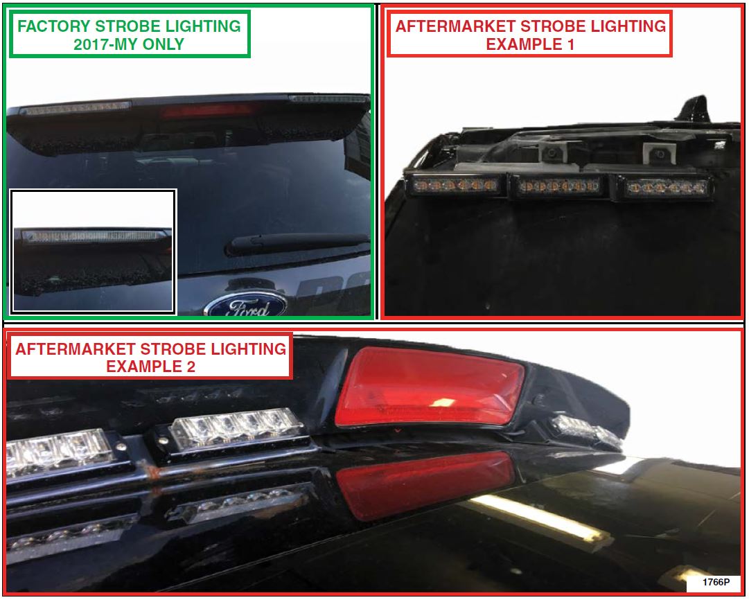
NOTE: Appearance may vary by lighting manufacturer.
IMPORTANT: Before removing aftermarket lighting and/or equipment from the liftgate spoiler, verify that the Service Department Management obtained customer approval to conduct this part of the service.
- Inspect the rear spoiler for any of the following:
- Is there aftermarket lighting or other equipment mounted to the spoiler? See Figure 9.
- Has the spoiler or vehicle been painted?
NOTE: All Police Interceptor Utility Spoilers are painted black from the factory.
FIGURE 9
Liftgate Spoiler Sealing
| 1/4″ Drive Ratchet (Power Tool & Hand Tool) |
| 1/4″ Drive 6 in (152 mm) Extension |
| 1/4″ Drive 7mm Shallow Socket |
| 1/4″ Drive Torque Wrench |
| 3/8″ Drive Ratchet (Power Tool & Hand Tool) |
| 3/8″ Drive 6 in (152 mm) Extension |
| 3/8″ Drive 13mm Twelve Point Socket |
| 3/8″ Drive Torque Wrench |
| Flat Faced Sheet Metal Hammer |
| Applicator Brush (Anti Corrosion Application) |
FIGURE 10
NOTE: Remove and do not reinstall any aftermarket lighting or other accessories mounted to the liftgate spoiler.
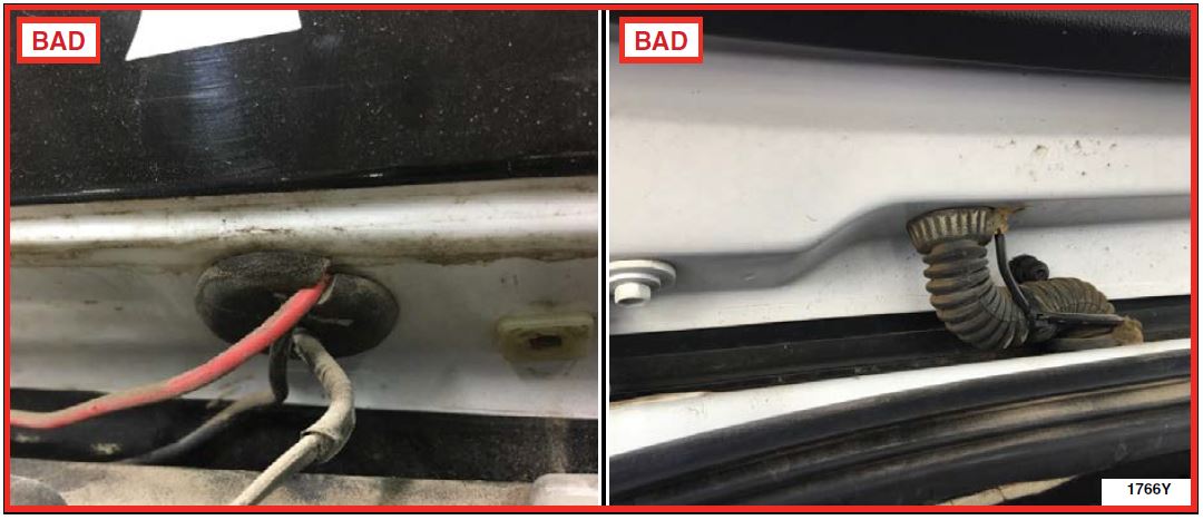
- Inspect for any aftermarket wiring pass throughs/holes that could affect the sealing ability of the spoiler. See Figures 11a and 11b.
FIGURE 11a FIGURE 11b
- Seal any leak paths created by the aftermarket wiring pass throughs/holes in the spoiler area with
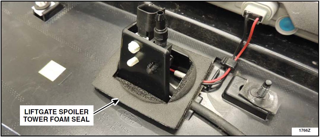
Motorcraft TA-2 seam sealer or equivalent. - Remove the liftgate spoiler tower foam seal. See Figure 12.
FIGURE 12
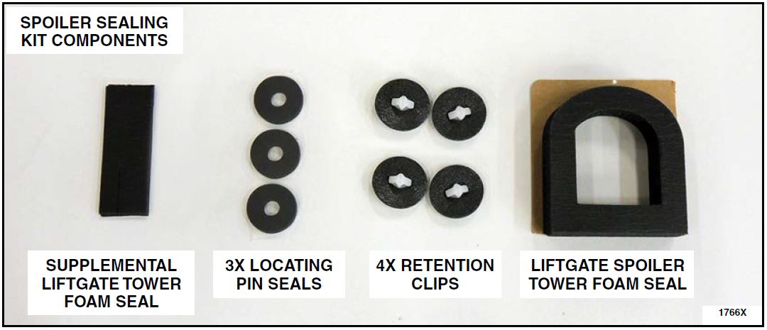
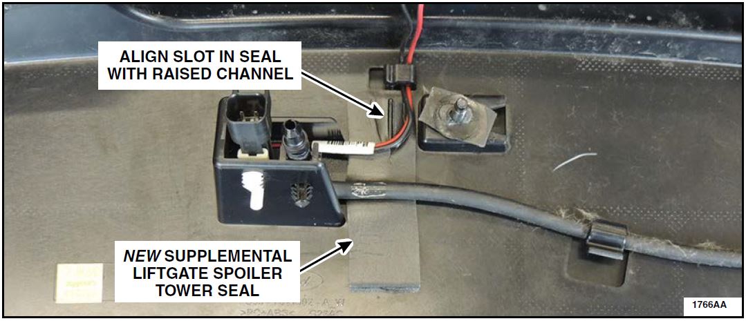
- Install a new supplemental liftgate spoiler tower seal underneath the wiring and washer line. Make sure the slot in the seal is aligned with the raised channel on the spoiler. See Figure 13.
FIGURE 13
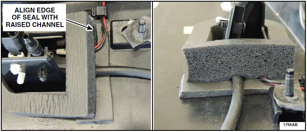
- Install a new liftgate spoiler tower seal. The flat edge of the seal must be aligned with the raised channel on the spoiler. See Figures 14a and 14b.
NOTE: Make sure the wiring and washer line are properly routed under the seal.
NOTE: Make sure the tower seal is installed as flat as possible, using even pressure around the perimeter to ensure a smooth wrinkle free seal.
FIGURE 14a FIGURE 14b
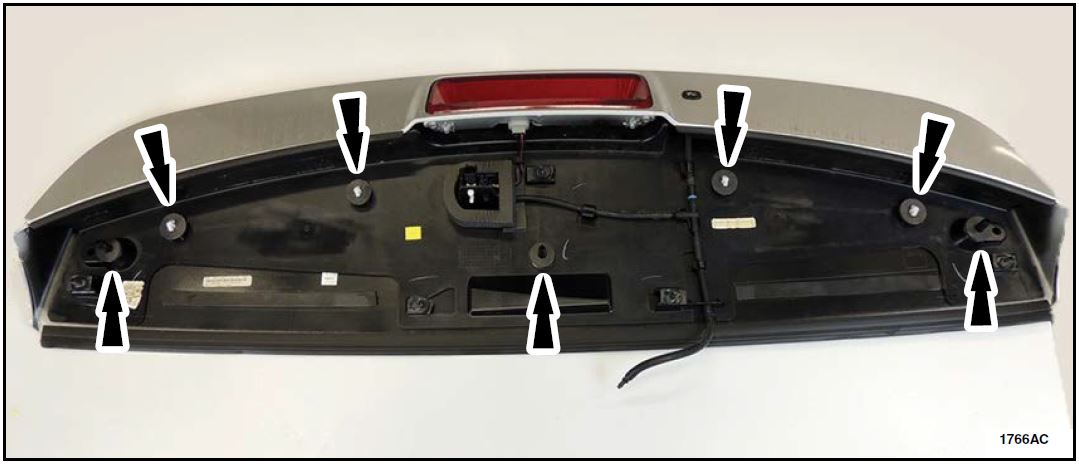
- Install four new retention clips and three locating pin seals. See Figure 15.
FIGURE 15
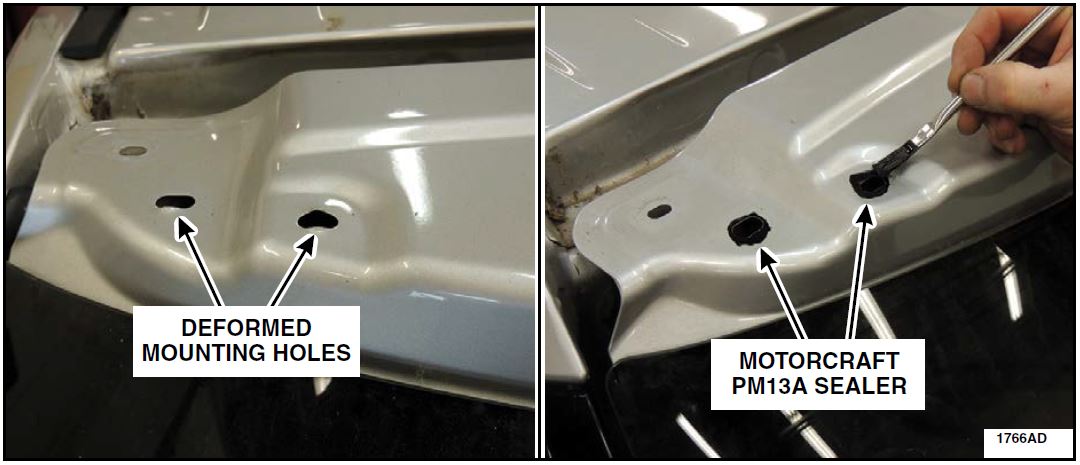
- Using a flat faced hammer, carefully straighten any deformed spoiler retaining clip mounting holes and apply Motorcraft PM13A sealer. See Figure 16.
FIGURE 16
- Leaving the liftgate trim panel, aftermarket light bar, and other accessories removed, install the liftgate spoiler. Please follow the WSM procedures in Section 501-08. Proceed to the Liftgate Trim Panel Sealing Procedure.
Liftgate Trim Panel Sealing
| 1/4″ Drive Ratchet (Power Tool & Hand Tool) |
| 1/4″ Drive 6 in (152 mm) Extension |
| 1/4″ Drive 8mm Shallow Socket |
| Trim Tool |
| Pencil |
FIGURE 17
- Using isopropyl alcohol and a clean cloth, clean the liftgate glass along the edge of the liftgate interior trim panel.
- Use a pencil on the rear glass to trace along the edge of the liftgate trim panel. This pencil line will be used in Step 10.
- Remove the liftgate trim panel. Please follow the WSM procedures in Section 501-05.
- Inspect the liftgate trim panel clips for any damage to the clips or clip mounting towers. Replace any clips that are found to be damaged or deformed. If a clip mounting tower is found to be damaged, replace the trim panel.
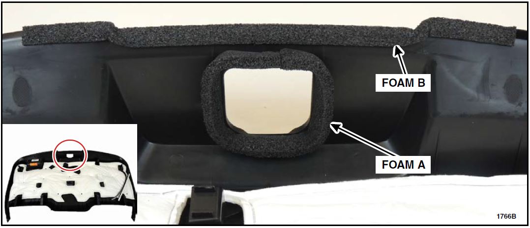
- Using isopropyl alcohol and a clean cloth, clean the liftgate trim panel where foam A and B will be installed. See Figure 18.
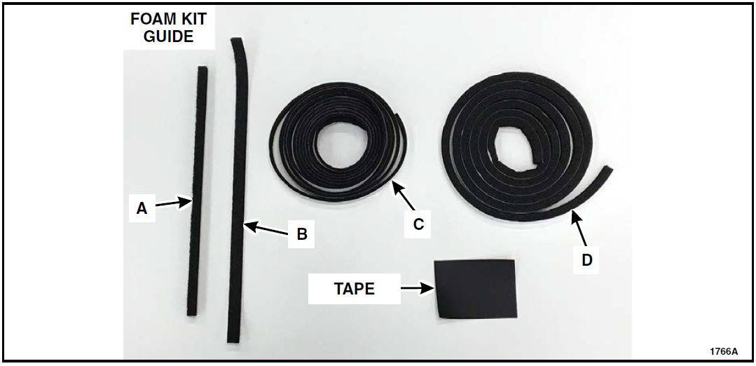
- Install foam A and B on the liftgate trim panel. See Figure 18.
FIGURE 18
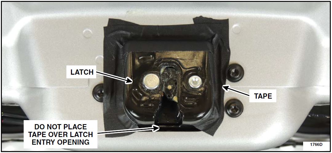
- Using isopropyl alcohol and a clean cloth, clean the area around the liftgate latch. Install the tape pieces around three (3) sides of the liftgate latch. See Figure 19.
FIGURE 19
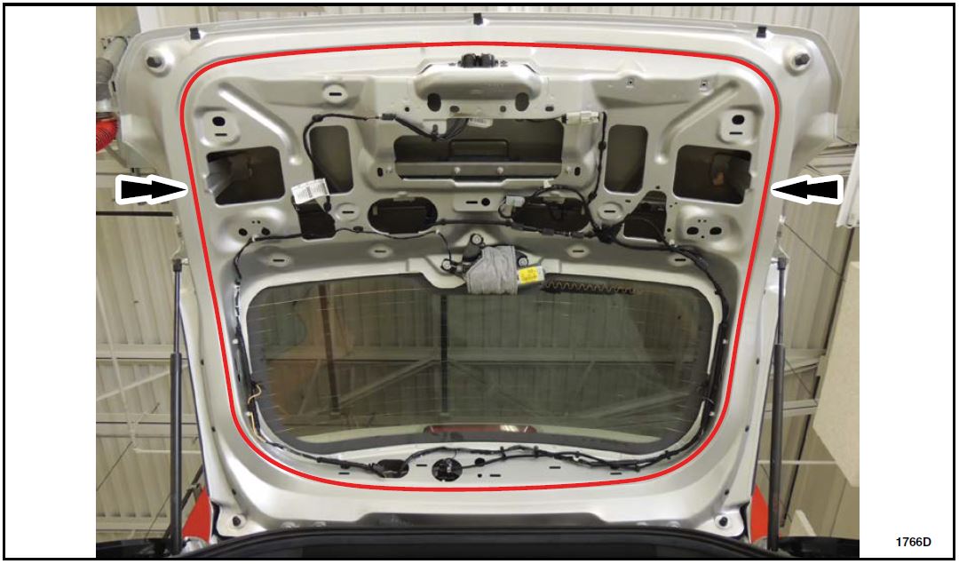
- Using isopropyl alcohol and a clean cloth, clean the liftgate sheet metal surface in the area highlighted. See Figure 20.
FIGURE 20
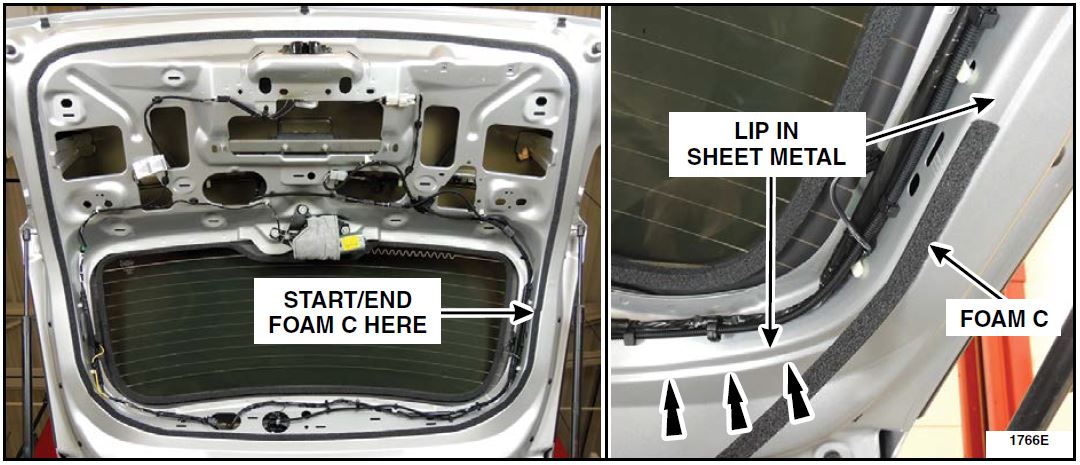
- Install foam piece C. The foam seal should be placed against the outer edge lip of the sheet metal to liftgate trim panel surface area. See Figures 21a and 21b
FIGURE 21a FIGURE 21b
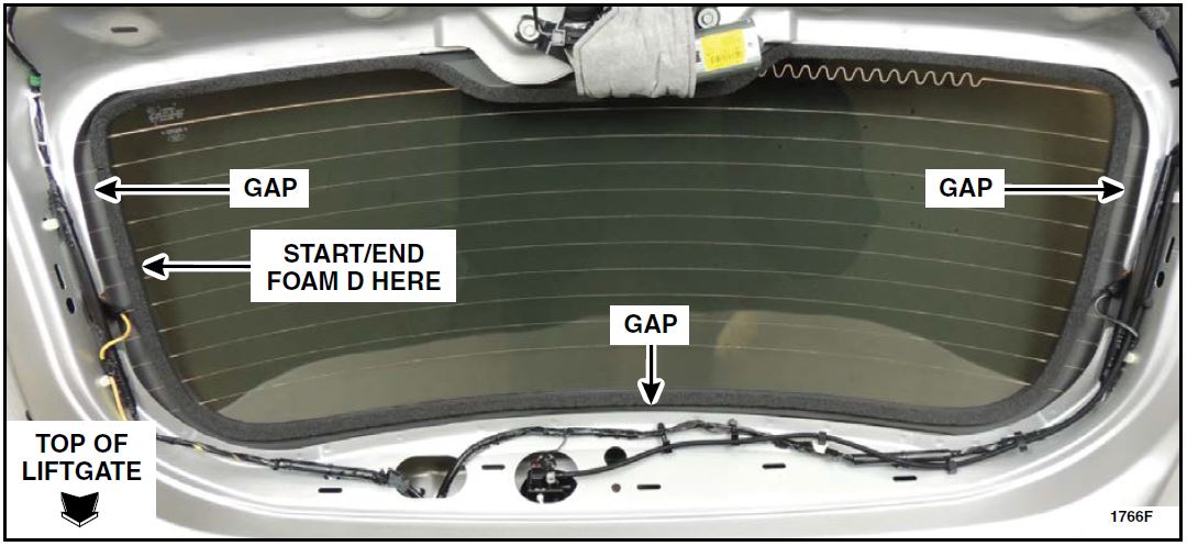
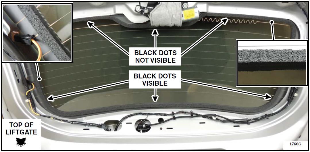
- Install foam piece D. See Figures 22 and 23.
- The foam should be centered over the pencil line from Step 2 to properly contact the liftgate trim panel.
- The top and sides of the foam seal must rest on the black silkscreen portion of the liftgate glass with the black dots still visible. See Figures 22 and 23.
- The bottom of the foam seal should cover up the black silkscreen dots on the liftgate glass. See Figures 22 and 23.
NOTE: There will be a gap between the foam seal and the top and sides of the liftgate body when foam D is installed properly.
FIGURE 22
FIGURE 23
- Inspect the liftgate trim panel for lights, pass throughs/holes and/or aftermarket equipment that could compromise the seal of the liftgate trim panel. Seal any breaches of the liftgate trim panel using mastic patch, left over foam tape, Dow Corning 7091 Adhesive/Sealant, or other robust sealing methods.
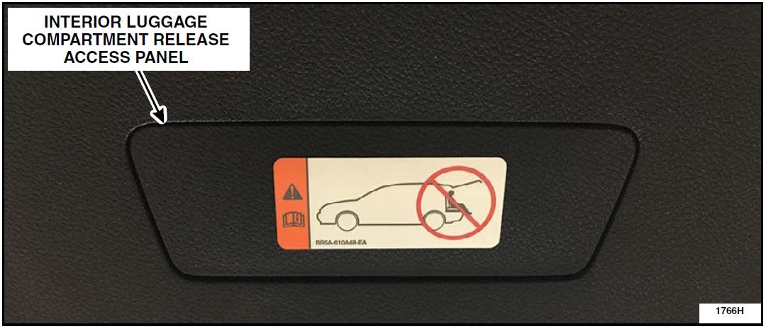
- Ensure the interior luggage compartment release access panel is properly installed in the lower liftgate trim panel. See Figure 24.
FIGURE 24
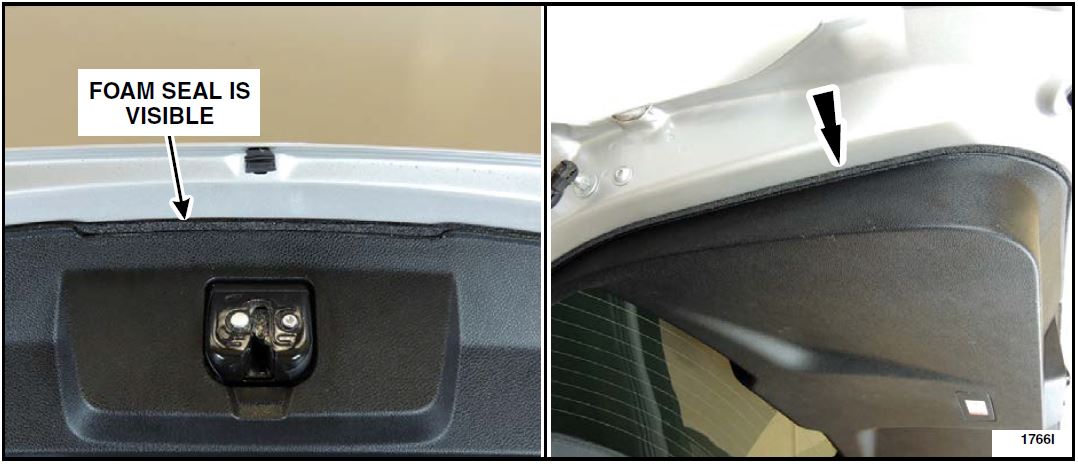
- Install the liftgate trim panel. Please follow the WSM procedures in Section 501-05. See Figures 25a and 25b.
NOTE: The clips where the upper and lower liftgate trim panels are joined are easily damaged on installation. Use care when installing the upper liftgate trim panel.
FIGURE 25a FIGURE 25b
Liftgate Drain Valve Inspection
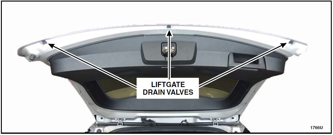
- With the liftgate open, remove all liftgate drain valves. 2013-2015 model year vehicles are equipped with two valves, 2016-2017 model year vehicles are equipped with three valves. See Figure 26.
FIGURE 26
- Clean the liftgate drain valves and the liftgate where the drains are fitted using isopropyl alcohol. Replace all drain valves that are damaged or missing.
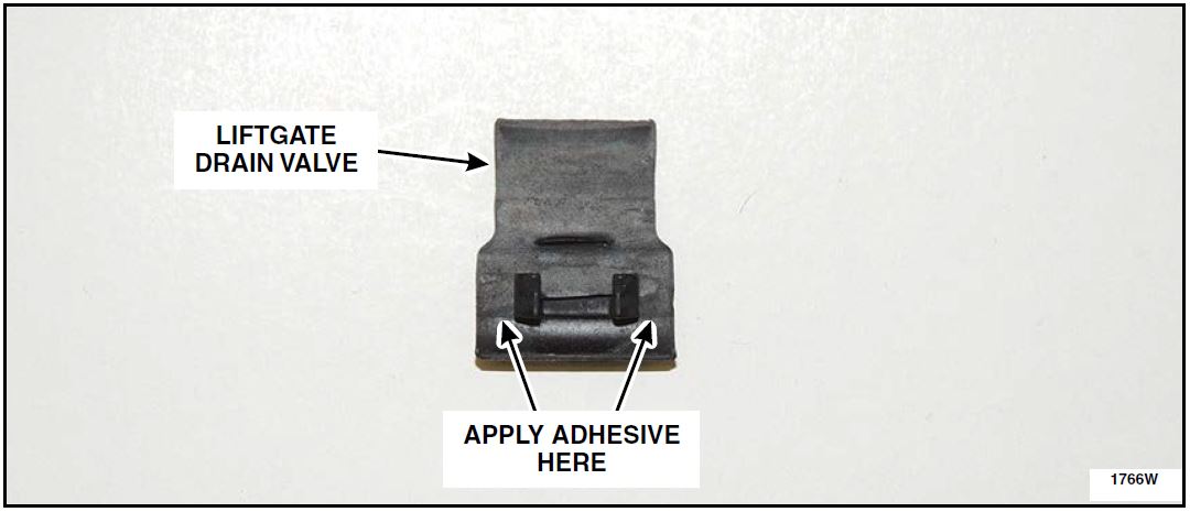
- Apply a drop of Motorcraft Instant Gel Adhesive TA-19-C or equivalent on each side of the liftgate drain valve attaching clip. Install the liftgate drain valves and hold the part in place for the period of time listed in the instructions on the package to allow the adhesive time to set. See Figure 27.
FIGURE 27
Exhaust Tip Replacement
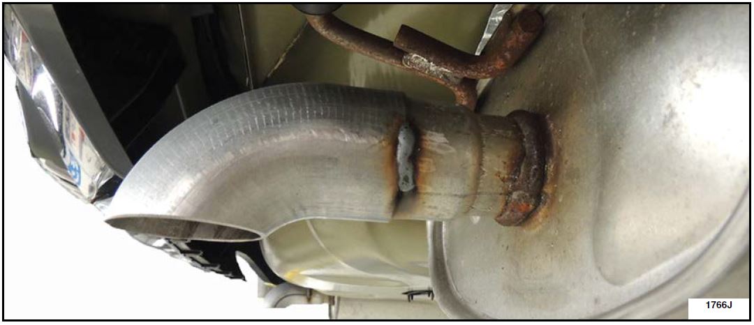
NOTE: The following procedure modifies the appearance of the vehicle by replacing the straight facing exhaust tips with downward facing exhaust tips. See Figure 28.
Recommended Tool List:
FIGURE 28
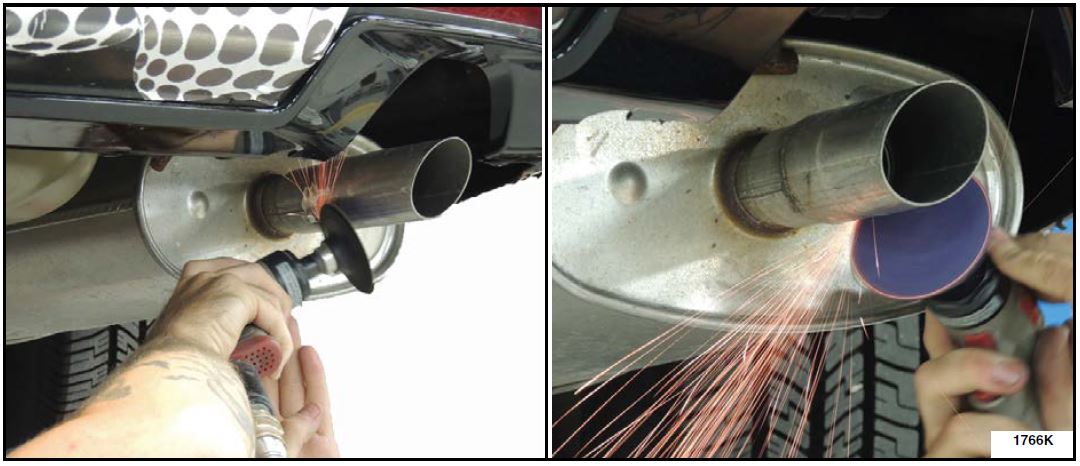
- Using a pneumatic handheld grinder and an abrasive disc, remove the exhaust tip welds on both sides and remove both exhaust tips. See Figures 29a and 29b.
FIGURE 29a FIGURE 29b
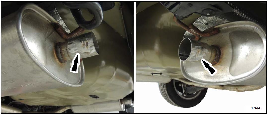
- Remove the remaining weld material on the mufflers with an abrasive disc until there is a smooth surface. See Figure 30.
FIGURE 30
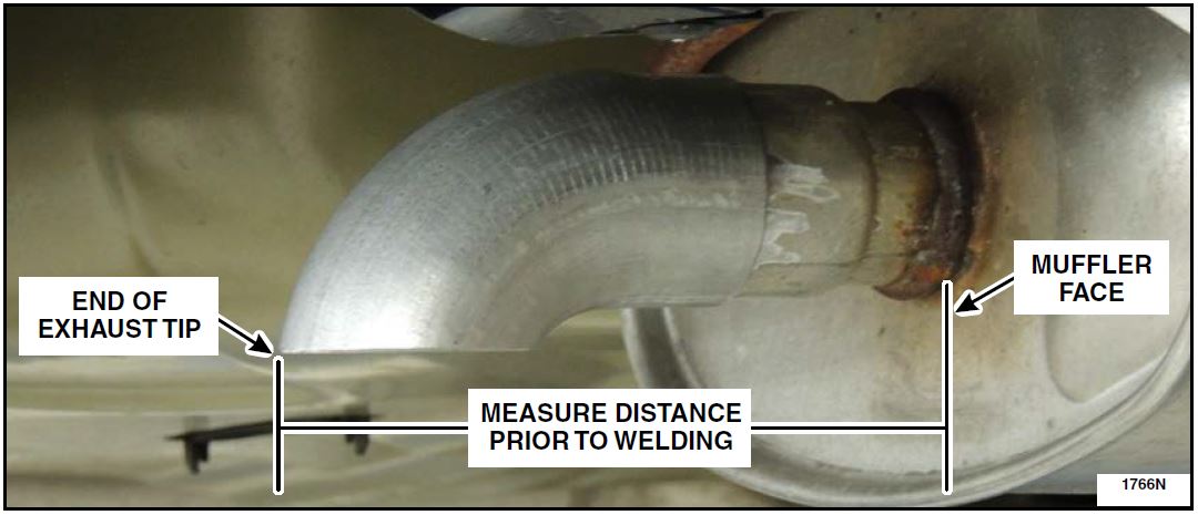
- Install the new exhaust tips. Use a tape measure or ruler to position the exhaust tip prior to welding.
See Figure 31.- 2013-2015 vehicles with 3.5L GTDI engine 7 5/8 in (193 mm).
- 2016-2017 vehicles with 3.5L GTDI engine 8 1/16 in (206 mm).
- All vehicles with 3.7L engine 6 7/8 in (174 mm).
FIGURE 31
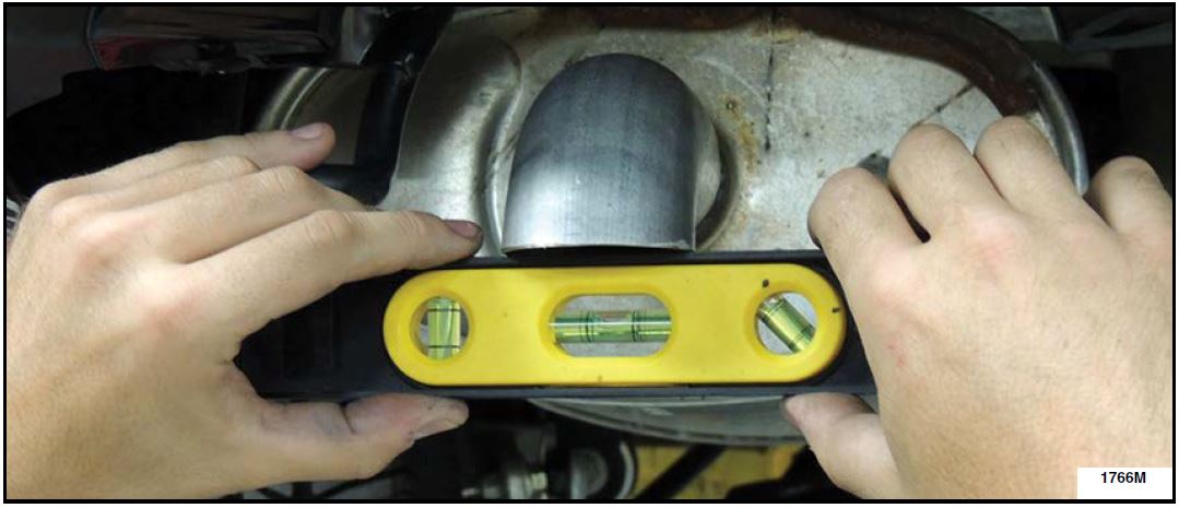
- Level the exhaust tips and clamp in position as required. See Figure 32.
FIGURE 32
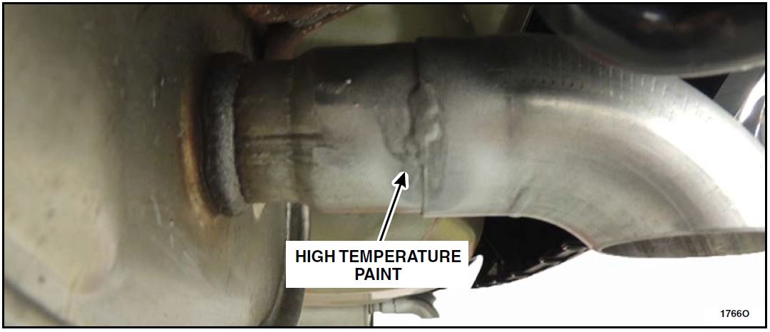
- Apply 1 in (25 mm) long weld beads along both sides of each exhaust tip using 308L or 409SS MIG welding wire. See Figure 33.
NOTE: If tips are welded using wire other than 308L or 409SS MIG welding wire, the welds must be protected from corrosion with two coats of high-temperature exterior paint rated at 500°F (260°C) or higher.
FIGURE 33
- Clean the body plugs and surrounding sheet metal, then apply the mastic patches to the underbody plugs as shown in Figure 34.
NOTE: Make sure each patch completely covers the body plug.
NOTE: Apply firm pressure when applying the mastic patch to the underbody plugs and surrounding sheet metal to ensure proper adhesion.
FIGURE 34
Check For Catalyst Efficiency DTCs
Recommended Tool List (3.5L GTDI Engines):
| 3/8″ Drive Impact Gun |
| 3/8″ Drive Ratchet |
| 3/8″ Drive 10mm Impact Socket |
| 3/8″ Drive 15mm Deep Impact Socket |
| 3/8″ Drive Impact Universal Swivel Joint |
| 3/8″ Drive 3 in (76 mm) & 11 in (279 mm) Impact Extensions |
| 3/8″ Drive Torque Wrench |
| 1/2″ Drive Impact Gun (RH Converter Only) |
| 1/2″ Drive 19mm Impact Socket (RH Converter Only) |
| Stud Remover / Installer |
| Trim Tool |
| Exhaust Gas Oxygen Sensor Socket 303-476 (LH Converter Only) |
Recommended Tool List (3.7L TiVCT Engines):
| 1/4″ Drive Ratchet (Power Tool) |
| 1/4″ Drive Flex Head Ratchet |
| 1/4″ Drive Shallow 10mm Socket |
| 1/4″ Drive 12 in (305 mm) Extension |
| 1/4″ Drive Torque Wrench |
| 3/8″ Drive Impact Gun |
| 3/8″ Drive Ratchet |
| 3/8″ Drive 13mm Deep Swivel Impact Socket |
| 3/8″ Drive 15mm Deep Swivel Impact Socket |
| 3/8″ Drive 7 in (178 mm) & 12 in (305 mm) Impact Extensions |
| 3/8″ Drive Torque Wrench |
| Long 10mm Ratchet Wrench |
| Stud Remover / Installer |
| Long Screwdriver (RH Converter Only) |
| Paint Stick (RH Converter Only) |
| Exhaust Gas Oxygen Sensor Socket 303-476 (RH Converter Only) |
NOTE: For stock/unsold vehicles, proceed to HVAC Module Reprogramming. It is not necessary to check for catalyst efficiency DTCs on stock/unsold vehicles.
- Perform a KOEO self-test on the PCM. Is DTC P0420 and/or P0430 present (including pending DTCs).
- Yes – Replace the catalyst as required. Please follow the WSM procedures in Section 309-00.
Proceed to the HVAC module reprogramming procedure. - No – Proceed to the HVAC module reprogramming procedure.
- Yes – Replace the catalyst as required. Please follow the WSM procedures in Section 309-00.
HVAC Module Reprogramming
- Reprogram the HVAC module using Integrated Diagnostic Software (IDS) release 106.07 or higher. Important Information for Module Programming
NOTE: When programming or reprogramming a module, use the following basic checks to ensure programming completes without errors.
- Make sure the 12V battery is fully charged before carrying out the programming steps and connect IDS/scan tool to a power source.
- Inspect Vehicle Communication Module (VCM) and cables for any damage. Make sure scan tool connections are not interrupted during programming.
- A hardwired connection is strongly recommended.
- Turn off all unnecessary accessories (radio, heated/cooled seats, headlamps, interior lamps, HVAC system, etc.) and close doors.
- Disconnect/depower any aftermarket accessories (remote start, alarm, power inverter, CB radio, etc.).
- Follow all scan tool on-screen instructions carefully.
- Disable IDS/scan tool sleep mode, screensaver, hibernation modes.
- Create all sessions key on engine off (KOEO). Starting the vehicle before creating a session will cause errors within the programming inhale process.
Recovering a module when programming has resulted in a blank module:
NEVER DELETE THE ORIGINAL SESSION!
a. Obtain the original IDS that was used when the programming error occurred during module reprogramming (MR) or programmable module installation (PMI).
b. Disconnect the VCM from the data link connector (DLC) and the IDS.
c. Reconnect the VCM to IDS and then connect to the DLC. Once reconnected, the VCM icon should appear in the corner of the IDS screen. If it does not, troubleshoot the IDS to VCM connection.
d. Locate the original vehicle session when programming failed. This should be the last session used in most cases. If not, use the session created on the date that the programming failed.
NOTE: If the original session is not listed in the previous session list, click the Recycle Bin icon at the lower right of the previous session screen. This loads any deleted sessions and allows you to look through them. Double-click the session to restore it.
e. Once the session is loaded, the failed process should resume automatically.
f. If programming does not resume automatically, proceed to the Module Programming menu and select the previously attempted process, PMI or MR.
g. Follow all on-screen prompts/instructions.
h. The last screen on the IDS may list additional steps required to complete the programming process.
Make sure all applicable steps listed on the screen are followed in order.
ATTACHMENT IV
NEW VEHICLE DEMONSTRATION / DELIVERY HOLD –
Customer Satisfaction Program 17B25 – Supplement #4
Certain 2013-2017 Model Year Police Interceptor Utility Vehicles
Exhaust Odor and Carbon Monoxide Complaints
KEY MESSAGES FOR DEALERS / Q&A
Safety is our top priority. To address police customers who drive modified vehicles in unique ways, we are covering the costs of specific repairs in every Police Interceptor Utility that may have exhaust odor and carbon monoxide concerns, regardless of modifications made after leaving Ford’s factory.
Key Messages
- Ford Motor Company engineering teams continue working with law enforcement agencies in their communities to investigate and address carbon monoxide concerns in some Ford Police Interceptor Utilities.
- Ford dealers will check and seal the rear of the vehicle where exhaust can enter, update the air conditioning to bring in more fresh air during heavy acceleration typical of police driving, check for engine codes that could indicate a damaged exhaust manifold and add downward facing exhaust tips that further direct exhaust away from the vehicle.
- We continue to investigate. We have not found levels of carbon monoxide in non-Police Ford Explorers that present a risk to safety by exceeding the thresholds of normal exposure in everyday life.
- We have tested Police Interceptor Utilities with exhaust odor concerns, finding variable levels of carbon monoxide, depending on how well the rear of the vehicle was sealed after installation of aftermarket police equipment.
- Unsealed holes can allow exhaust gases to enter the vehicle during aggressive acceleration and high speed driving unique to police use.
- If a customer believes their vehicle may be experiencing an issue, they should bring it to a Ford dealer for inspection. Customers also can call a dedicated hotline at 888-260-5575.
| Q | How do you know there are no carbon monoxide issues with regular Explorers? |
| A | We continue to investigate. We have not found levels of carbon monoxide in non-Police Ford Explorers that present a risk to safety by exceeding the thresholds of normal exposure in everyday life. |
| Q | How many vehicles has Ford fixed so far? |
| A | Ford has worked side-by-side with more than a dozen police agencies nationwide to inspect and repair more than 50 vehicles in cities and towns, such as Auburn, Massachusetts and Galveston, Texas |
| Q | Are you considering a recall? |
| A | Our decisions are driven by the data available. When the data indicates a safety recall is needed, we move quickly on behalf of our customers. |
| Q | What repairs will dealers make? |
| A | Ford dealers will check and seal the rear of the vehicle where exhaust can enter, update the air conditioning to bring in more fresh air during heavy acceleration typical of police driving and check for PCM codes that could indicate an exhaust catalyst efficiency concern. |
| Q | What is your response to complaints from police on cracked exhaust manifolds that may be causing carbon monoxide concerns? |
| A | All of our testing to date has not shown cracked exhaust manifolds contributing to the carbon monoxide levels in Police Interceptor Utilities. We are continuing to investigate. |
| Q | Will you replace cracked exhaust manifolds? |
| A | If PCM codes indicate an exhaust catalyst efficiency concern is present in the vehicle, we will replace that exhaust catalyst/manifold assembly under our program. |
| Q | Does Ford recommend police departments put in carbon monoxide detectors in their vehicles? Will Ford pay for them? |
| A | We encourage our police customers to bring their vehicle to their local Ford dealer. |
| Q | How long does this program run? |
| A | For vehicles covered by this program, coverage will remain in effect until September 30, 2018. |
| Q | Will Ford reimburse for repairs/TSB work already done? |
| A | Yes. If a police customer or consumer already had repairs for the specific repairs under this concern, Ford will reimburse the customer for those costs. Refer to Attachment I in the dealer bulletin for details. |
| Q | Why is Ford recommending removal of aftermarket lighting and/or equipment from the liftgate spoiler? |
| A | During our investigation, Ford found a wide assortment of aftermarket lighting and/or equipment products and installation practices. Ford can only ensure proper sealing of the spoiler when aftermarket lighting and/or equipment are removed and the spoiler is resealed. |
| Q | Is Ford recommending that no aftermarket lighting and/or equipment can be attached to the liftgate spoiler? |
| A | Ford strongly recommends that fleets work with their installers and/or equipment suppliers to ensure that both the equipment and installation practices are robust and do not compromise vehicle sealing. Refer to the Customer Information Form for additional details. |
| Q | What should a Ford dealer do if a fleet declines the service to remove the aftermarket lighting and/or equipment from the spoiler, and reseal the spoiler? |
| A | Dealers should complete all other steps of the field service action, document on the repair order that the spoiler sealing service was declined, print and provide the customer with the Customer Information Form (see bulletin attachments), and release the vehicle to the customer. |
| Q | Is Ford paying to replace aftermarket lighting and/or equipment if removed from the spoiler? |
| A | No. Replacement aftermarket lighting and/or equipment is not part of 17B25. |
| Q | Can Ford recommend a brand and model of aftermarket lighting and/or equipment that allows for proper sealing when mounted to the spoiler? |
| A | Currently, the only Ford approved spoiler lighting solution is the Ford Rear Spoiler Traffic Warning Lights option (96T), which is compatible with 2017 Police Interceptor Utilities. Police equipment suppliers are working to develop solutions for existing spoiler mounted lighting and/or equipment products. |
17B25 – Customer Information Form
Liftgate Spoiler – Aftermarket Lighting and/or Equipment
Your vehicle is equipped with aftermarket lighting and/or equipment mounted to the liftgate spoiler that may prevent proper sealing. You have instructed the Dealer not to remove this equipment.
There is a wide assortment of aftermarket lighting and/or equipment products in the marketplace. In addition, installation practices vary greatly. Because of this variation, Ford cannot ensure proper sealing of the spoiler to the vehicle without removing the lights and/or equipment. Ford recommends that you work with your installer and/or equipment supplier to ensure proper sealing of the spoiler.
NOTE: Police equipment suppliers are working to develop solutions for existing spoiler mounted lighting and/or equipment products.
Examples of Liftgate Spoiler Aftermarket Lighting and/or Equipment and Installation Concerns:
- Brackets positioned between the spoiler and the liftgate (See Figure 1)
- Lighting and/or equipment that forces the spoiler out of position creates a gap between the spoiler and the liftgate (See Figure 2)
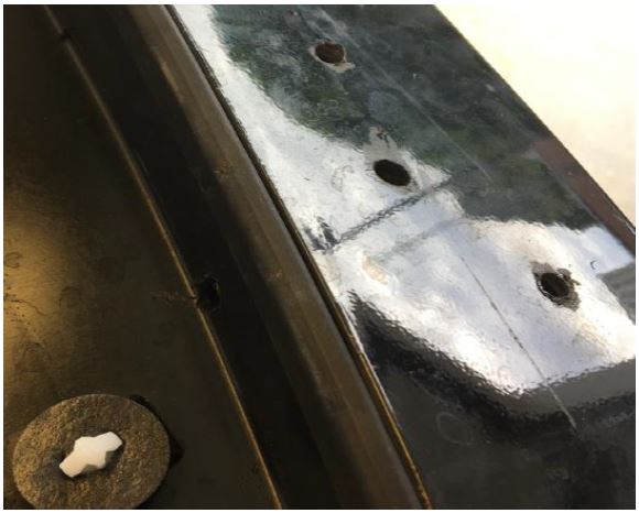
- Unsealed holes drilled in the spoiler or liftgate (See Figures 3 and 4)
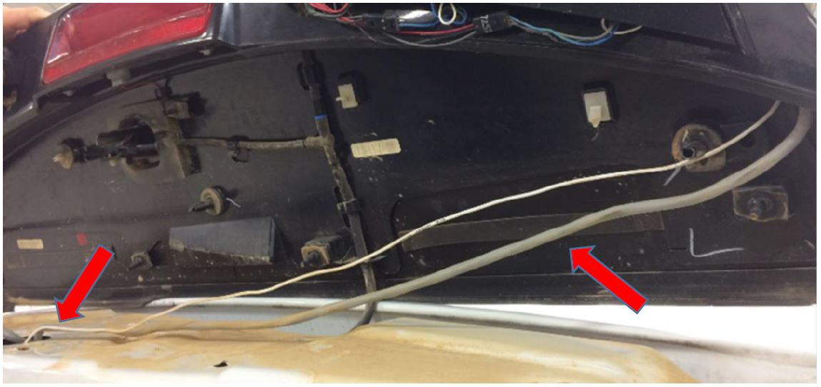
- Wiring for lighting and/or equipment routed from the spoiler to the vehicle in a manner that damages the seals between the spoiler and the vehicle (See Figures 5 and 6)
- When the spoiler is removed to install aftermarket lights and/or equipment, the spoiler attachment clips and seals may be damaged. If the spoiler was removed from the vehicle, the spoiler attachment clips and seals should be replaced. Use part number HB5Z-78442K03-A
Figure 1
Figure 2
Figure 3
Figure 4
Figure 5
ATTACHMENT VI
NEW VEHICLE DEMONSTRATION / DELIVERY HOLD –
Customer Satisfaction Program 17B25 – Supplement #4
Certain 2013-2017 Model Year Police Interceptor Utility Vehicles
Exhaust Odor and Carbon Monoxide Complaints
6 Important Facts About Carbon Monoxide and Police Vehicles
In response to police departments raising concerns about the possible presence of carbon monoxide (CO) in some Ford Police Interceptor Utilities, Ford Motor Company has prepared the following fact sheet to provide our customers with important information about CO, workplace safety and how to appropriately check for CO.
- CO is measured in two ways: In the air, it is measured in parts per million (ppm) or in the blood, it is measured as the percentage of hemoglobin bound to CO (or carboxyhemoglobin [COHb]).
- The U.S. Department of Labor Occupational Safety and Health Administration (OSHA) sets a standard for the Workplace of 50 ppm average over 8 hours.
- Instantaneous peak readings showing CO levels in parts per million at a single point in time do not provide an accurate depiction of an individual’s dose.
- In general, noticeable symptoms of CO exposure (shortness of breath with moderate exertion or possible headache) among healthy adults occur after several hours breathing average CO levels of 100 ppm; more severe symptoms among health adults are generally associated with prolonged exposure to >100 ppm.
- CO readings should only be performed with a scientifically calibrated detector, such as the RAE Systems ToxiRae PRO CO Monitor, Otis Tocsin OI-315 or Industrial Scientific Tango TX1.
- CO monitor readings can be affected by interference from police radios, radar guns or exposure to in-car chemicals, such as vapors from cleaners, solvents, air fresheners and other chemicals that could cause false readings. Additionally, monitors should not be left in a parked vehicle in warm or cold weather.
# # #
September 2017
Customer Satisfaction Program 17B25
Programa de satisfacción del cliente 17B25
Mr. John Sample
123 Main Street
Anywhere, USA 12345
Your Vehicle Identification Number (VIN): 12345678901234567
At Ford Motor Company, we are committed not only to building high quality, dependable products, but also to building a community of happy, satisfied customers. To demonstrate that commitment, we are providing a no-charge Customer Satisfaction Program for your vehicle with the VIN shown above.
| Why are you receiving this notice? | Ford Motor Company has discovered holes and unsealed spaces in the back of some Police Interceptor Utility vehicles that had police or other emergency equipment installed after leaving Ford’s factory.
When a police or fire department routinely installs customized emergency lighting, radios and other equipment, they drill mounting and wiring access holes into the rear of the vehicle. |
| What is the effect? | If equipment installation requires drilling new holes and/or routing wires, and the modifications are not properly sealed, it creates an opening where exhaust could enter the cabin. |
| What will Ford and your dealer do? | Ford Motor Company has authorized your dealer to inspect and repair body seals, grommets and liftgate spoiler sealing systems, seal the lift gate interior trim panel, install new muffler tips, reprogram the ventilation (HVAC) module, and check the Powertrain Control Module (PCM) for certain diagnostic trouble codes, free of charge (parts and labor) under the terms of this program.
This Customer Satisfaction Program will be in effect until September 30, 2018 regardless of mileage. Coverage is automatically transferred to subsequent owners. |
| How long will it take? | The time needed for this repair is less than one-half day. However, due to service scheduling requirements, your dealer may need your vehicle for a longer period of time. In addition, your vehicle will require an inspection to determine if parts need to be ordered |
| What should you do? | Please call your dealer without delay and request a service date for Customer Satisfaction Program 17B25. Provide the dealer with the VIN of your vehicle. The VIN is printed near your name at the beginning of this letter.
If you do not already have a servicing dealer, you can access www.Fordowner.com for dealer addresses, maps, and driving instructions. Ford Motor Company wants you to have this service action completed on your vehicle. The vehicle owner is responsible for making arrangements to have the work completed. NOTE: You can receive information about Recalls and Customer Satisfaction Programs through our FordPass App. The app can be downloaded through the App Store or Google Play. In addition there are other features such as reserving and paying for parking in certain locations and controlling certain functions on your vehicle (lock or unlock doors, remote start) if it is equipped to allow control. |
| Have you previously paid for this repair? | If you have previously paid for a repair that addresses the issue described in this letter, you still need to have this service action performed to ensure the correct procedures were used.
If the previously paid for repair was performed before the date of this letter, you may be eligible for a refund. Refunds will only be provided for the cost associated with the inspection and repair of vehicles with exhaust odor and carbon monoxide complaints using TSB 16-0166 or 17-0044. To verify eligibility and expedite reimbursement, give your paid original receipt to your dealer before March 31, 2018. To avoid delays, do not send receipts to Ford Motor Company. |
| What if you no longer own this vehicle? | If you no longer own this vehicle, and have an address for the current owner, please forward this letter to the new owner.
You received this notice because our records, which are based primarily on state registration and title data, indicate that you are the current owner. |
| Can we assist you further? | If you have difficulties getting your vehicle repaired promptly and without charge, please contact your dealership’s Service Manager for assistance.
RETAIL OWNERS: If you have questions or concerns, please contact our Ford Customer Relationship Center at 1-866-436-7332 and one of our representatives will be happy to assist you. If you wish to contact us through the Internet, our address is: www.Fordowner.com. For the hearing impaired call 1-800-232-5952 (TDD). Representatives are available Monday through Friday: 8:00AM – 8:00PM (Eastern Time). FLEET OWNERS: If you have questions or concerns, please contact our Fleet Customer Information Center at 1-800-34-FLEET, choose Option #3, and one of our representatives will be happy to assist you. If you wish to contact us through the Internet, our address is: www.fleet.ford.com. Representatives are available Monday through Friday: 8:00AM – 8:00PM(Eastern Time). |
| Para asistencia en Español | Visite nuestro sitio web para ver este anuncio en Español al siguiente dirección: https://es.owner.ford.com/recall .
Si necesita ayuda o tiene alguna pregunta, por favor llame al Centro de Relación con Clientes al 1-866-436-7332 y presione 2 para Español. |
Thank you for your attention to this important matter.
Ford Customer Service Division
Customer Satisfaction Program 17B25 – Supplement #5
September 26, 2018
 Loading...
Customer Satisfaction Program 17B25 – Supplement #4
November 13, 2017
nhtsa.gov/recalls?nhtsaId=10127430
 Loading...
Customer Satisfaction Program 17B25 – Supplement #3
October 25, 2017
 Loading...
Customer Satisfaction Program 17B25 – Supplement #1
September 21, 2017
 Loading...
Customer Satisfaction Program 17B25
September 13, 2017
 Loading...
Advance Notice – Customer Satisfaction Program 17B25
July 28, 2017
 Loading...
Reprogramming
Service Information & Reprogramming
Module Reprogramming
| Diagnostic Software | Interface Device | Complete Vehicle Diagnostics | Module Programming | ||
| 1996-2017 Model Year |
2018-Present Model Year |
1996-2017 Model Year |
2018-Present Model Year |
||
| IDS/FDRS | VCM, VCM II , VCMM , VCMM |
X | X | X | X |
| FJDS/FDRS | Compatible J2534 Devices (Including VCM II  and VCMM) and VCMM) |
X | X | X | |
Detailed system requirements, installation, and support information for each product is located under the diagnostics tool support tab for each product.
Integrated Diagnostic Software (IDS) / Ford Diagnosis & Repair System (FDRS)
For use with VCM I, VCM II , VMM and VCMM hardware devices only. The complete factory Ford Motor Company vehicle diagnostic tool that provides complete dealership level vehicle diagnostic coverage for all 1996 to present Ford, Lincoln and Mercury
 vehicles. The IDS software includes time based access to the IDS software, software updates and calibration files.
Ford J2534 Diagnostic Software (FJDS) / Ford Diagnosis & Repair System (FDRS)
For use with compatible J2534 hardware devices. FJDS software provides Ford Module Programming functionality that covers 1996 to present Ford, Lincoln and Mercury module reprogramming functions, plus complete dealership level vehicle diagnostic software for all 2018 to present Ford and Lincoln vehicles. The FJDS software license includes time based access to the FJDS software, software updates and calibration files.
| CarDAQ-Plus 3 All Makes J2534 Reprogramming Tool | |
| CarDAQ-Plus 2 Diagnostic Code Reader and J2534 Programming Tool | |
| CarDAQ-Plus | |
| CarDAQ-M | |
| VSI J2534 ECU Reprogrammer | |
Latest Calibration Information
Module Build Data (As-Built)
Use VIN to obtain As-Built data
- J2534 Pass-Thru Programmer: TOPDON RLink J2534 is an advanced diagnostic and reprogramming tool that support all J2534 protocols, as well as D-PDU, CAN-FD and DoIP, ensuring compatibility with a wide range of modern vehicles. It offers extensive versatility with support for over 17 major automotive brands, including Chrysler, Ford, GM, Nissan, Toyota, Honda, Subaru, Land Rover/Jaguar, Volvo, Wuling, Volkswagen, Mercedes-Benz, and BMW, and so on, enjoy dealership-level functions at your fingertips
- All-in-One OEM Diagnostics: This J2534 ECU programming tool elevates your automotive repair capabilities to new heights by delivering complete OEM diagnosis. Boasting comprehensive full-system diagnostics, intuitive repair guides, advanced ECU programming and coding, common reset services, a vast library of repair information and more, this all-in-one solution empowers technicians to effortlessly tackle complex vehicle issues with ease
- Proven Performance You Can Trust: Backed by over 10000 real vehicle tests and benefit from a wealth of practical experience, this OEM reprogramming tool guarantees stable and exceptional performance. Supported by TOPDON's dedicated technical experts with in-depth knowledge of both auto repair and J2534 Pass-Thru programming, the RLink J2534 provides prompt and professional assistance, ensuring a smooth setup and reliable compatibility
- Integrated Excellence, Always Up-to-Date: Featuring the exclusive RLink Platform to provide a streamlined experience with one-click driver installation and management, ensuring flawless integration with your OE software, maintaining the original performance quality. The built-in operation guide makes mastering OE software quick and easy, so you can get started right away. Plus, with lifetime free updates, your diagnostics will stay current with the latest drivers and innovations
- Efficiency Meets Versatility: Engineered to support three CAN channels simultaneously - CAN FD and CAN-CC included, giving you the edge in fast troubleshooting. To perfectly synchronized with the OE software, please diagnose with active subscriptions and make sure your computer system is running a compatible 64-bit Windows version (7, 8, 10 or later) to fully leverage the power of RLink J2534. *We don't provide extra OE software
- 【J2534 PROTOCOL WITH SMARTLINKC】 LAUNCH X431 PRO3S+ ELITE scan tool with newly upgraded smartlinkC V2.0. The SmartLinkC is a communication interface supporting J2534 specifications. Of course, it also can be used as a J2534 PassThru device, working together with the PC installed with the OEM diagnostic software to perform the J2534 protocol.J2534 protocol is the only solution for problems ranging from driveability and loss of power to poor fuel economy.
- 【INTELLIGENT TOPOLOGY MAP TO FASTER FULL SYSTEMS DIAGNOSIS】 X431 PRO3S+ELITE bidirectional scan tool with new-added intuitive topology mapping. Harnesses intuitive topology mapping for comprehensive visualization of the vehicle all system. It shows all available control units in different colors, the numbers of system, the scanned system, and the scan results, bringing maximum convenience & superfast speed for you to do swift diagnosis & high-level repairs.
- 【TOP HARDWARE CONFIGURATION, UPGRADED OF LAUNCH X431 PRO3S+】 LAUNCH X431 PRO3S+ELITE diagnostic scanner possess with Android 10.0 OS; CPU 4-Core Processor, 2.0 GHz. Greatly increased the speed of running multiple task. 2.4GHz/5GHz; 6300mAh/7.6V stronger battery capacity; 10.1 Inch Touchscreen with 8MP camera; AUTO VIN; 4GB+64GB storage memory; 20X faster transmission rate, save more vehicle documents and customer data; Supports 25+ Software Languages, such as EN, DE, FR, SP nd JP and so on.
- 【3000+ ACTIVE TEST/BI-DIRECTIONAL CONTROL LAUNCH SCANNER】 LAUNCH X431 PRO3S+ELITE HD automotive scanner is a cost-effective bidirectional scanner that deserves owned by every repairing DIYers and mechanics. You can easily send command signal at fingertips from the scanner to various module actuators to test component integrity and functionality in minutes or even seconds to tell if replacement or repair is needed.
- 【COMPLETE 60+ HOT RESETS, CALIBRATION, INITIALIZATION, RELEARN】 LAUNCH X431 PRO3S+ELITE SmartLinkC escaner automotriz professional enjoys 60+ special service, such as Oil Reset, ABS brake bleed, EPB, SAS, BMS, Suspension, Injector reset, Power Balance, Turbo Calibration, VGT, Transmission Adaption, Throttle Adaptation, matching and etc. rigorous on-site testing has been performed to ensure 100% availability.
- 🌐【Works with Autel Elite II Elite MS908 MS908S Pro II MS908CV II MK908P MK908 Pro II】Autel J2534 work with these tools to program ECUs on specific BM.W/ BE.NZ for specific functions. ★★NOTE: J2534 CANNOT directly work with these single devices. After you received the J2534, you HAVE TO send us both the S/N(12 digits) of your scanner MS908S(etc.) and J2534. So, technically, Autel engineers can help you bind J2534 with your devices. If need any supports, contact us via: 🚘auteldirect @ outlook. com🚘.
- 🌐【SAE J2534-1 & J2534-2 Standards】Autel MaxiFlash Elite J2534 is a fully compliant SAE J2534-1 & SAE J2534-2 (March 2006) device, which performs standard PassThru J2534 functionality: Compatible with for Toyota Techstream, Volvo VIDA, Honda HDS, Jaguar-Land Rover IDS and BM.W 3G for OEM diagnostics. Autel MaxiFlash J2534 is also specially designed to provide users with P-C communication and ECU reprogramming capabilities on any modern vehicle diagnostic bus, reliability and flexibility.
- 🌐【High-speed Transmission Speed】Autel MaxiFlash Elite Reprogramming Device J2534 supports simultaneous communication definition in J2534-1, running 3 protocols at the same time, which greatly improves reprogramming and diagnostic speed. Embedded with the ARM9 Dual-core processor (clocked up to 500MHz), which further boosts the communicating speed to save more times and win more business.
- 🌐【Multiple Devices Connected with P-C】Autel MaxiFlash Elite J2534 also supports multiple device connections to the P-C, which can operate diagnostic and reprogramming functions on more than one vehicle at the same time. Autel MaxiFlash Elite J2534 built-in wireless and data storage, which can update via Internet. It also ensures quickly reprogramming even the newest controllers.
- 🌐【Extensive Compatibility】Autel MaxiFlash J2534 is compatible with Toyota Techstream, Volvo VIDA, Honda HDS, Jaguar-Land Rover IDS and BM.W 3G for OEM diagnostics. To check compatibility, please contact 🚘auteldirect @ outlook . com🚘 directly for satisfaction-guaranteed support!
- ALL OF THE J2534 PROTOCOLS - This single unit has all of the protocols you need for your OEM J2534 reprogramming and diagnostics including the latest in DoIP and CanFD
- J2534 TECHNICAL SUPPORT - FREE for the life of the tool. Staffed by technicians who understand vehicle repair and J2534 Pass‑thru
- TOOLBOX WITH OEM APPLICATION DESCRIPTIONS - educational video tutorials and real-time news – Giving you the confidence and up-to-date knowledge to get the job done
- J2534 v05.00 API - The newest version of J2534 to give you the latest in pass-thru technology
- FUTURE PROOF WITH 4 CAN CHANNELS - Going beyond the 3 required by select Chrysler/FCA models, CarDAQ-Plus 3 also provides a 4th to meet the needs of future OEM applications
- CUSTOM-DESIGNED FOR USE WITH FORSCAN: Works with all FORScan compatible vehicles and is recommended by the FORScan Team
- DEALERSHIP-LEVEL DIAGNOSTICS: OBDLink EX supports all Ford protocols, modules, and advanced features of FORScan
- ELECTRONIC SWITCH allows FORScan to access all CAN buses simultaneously and enables advanced functions not possible with “toggle switch” adapters
- MAXIMUM THROUGHPUT -- up to 20 times faster than “toggle switch” adapters
- ROCK-SOLID CONNECTION avoids data corruption and dropped packets
- [J2534 COMPLIANT] - The Mastertech II is a J2534-1 and J2534-2 compliant VCI for OEM reprogramming and diagnostic applications
- [FULLY VALIDATED BY TOP 6 OEMS] - Mastertech II has been fully validated to operate with the top 6 OEM reprogramming applications: GM, Ford, FCA, Nissan/Infinity, Honda/Acura, and Toyota/Lexus
- [PRE-CONFIGURED] - The pre-configured wireless and wired connections make it quick and easy to connect to a vehicle from your PC (requires PC compliant with OE specifications and software)
- [RIGHT TO REPAIR] - Supports 'Right to Repair' (R2R) initiatives
- [COMPREHENSIVE KIT] - Kit includes: VCI, WiFi adapters (wireless PC to VCI), J1962 Cable (connect to vehicle), USB cable (connect to PC for firmware updates and setup), and Quick Start Guide
Last update on 2025-05-10 / Affiliate links / Images from Amazon Product Advertising API
This product presentation was made with AAWP plugin.
