| “This site contains affiliate links for which OEMDTC may be compensated” |
November 19, 2013
TO: All U.S.Ford and Lincoln
 Dealers
SUBJECT: DEMONSTRATION / DELIVERY HOLD – Customer Satisfaction Program 13B11
Certain 2014 Model Year F-Super Duty 2-Wheel Drive 137” Wheelbase Vehicles
6R140 Automatic Transmission Lubricant Passage Repair
PROGRAM TERMS
This program will be in effect through May 31, 2014. There is no mileage limit for this program.
URGENCY / EXPIRATION DATE
This Customer Satisfaction Program has an expiration date of May 31, 2014 to encourage dealers and customers to have this service performed as soon as possible.
We recommend dealers utilize their FSA VIN list name and address (available on November 25, 2013) to contact customers with affected vehicles. This will help minimize the number of vehicles that exhibit symptoms of noise and vibration and may require a more extensive repair.
AFFECTED VEHICLES
Certain 2014 model year F-Super Duty 2-wheel drive 137” wheelbase vehicles with an Automatic
Transmission built at the Kentucky Truck Assembly Plant from July 15, 2013 through October 16, 2013. Affected vehicles are identified in OASIS. In addition, for a list of vehicles assigned to your dealership, visit https://web.fsavinlists.dealerconnection.com. This information will be available on November 19, 2013.
REASON FOR THIS PROGRAM
In the affected vehicles, a passage in the transmission case that directs transmission fluid to the bushing for the driveshaft slip yoke was not manufactured correctly. A lack of fluid at the driveshaft slip yoke bushing will result in noise, vibration, and premature wear of the extension housing bushing and driveshaft slip yoke.
SERVICE ACTION
Before demonstrating or delivering any of the vehicles involved in this program, dealers are to repair the transmission as directed in the technical information, Attachment III. This service must be performed on all affected vehicles at no charge to the vehicle owner.
OWNER NOTIFICATION MAILING SCHEDULE
Owner Letters are expected to be mailed the week of December 2, 2013. Dealers should repair any affected vehicles that arrive at their dealerships, whether or not the customer has received a letter.
ATTACHMENTS
Attachment I: Administrative Information
Attachment II: Labor Allowances and Parts Ordering Information
Attachment III: Technical Information
Owner Notification Letter
QUESTIONS & ASSISTANCE
Special Service Support Center (Dealer Assistance Only) 1-800-325-5621
Sincerely,
Michael A. Berardi
ATTACHMENT I
DEMONSTRATION / DELIVERY HOLD – Customer Satisfaction Program 13B11
Certain 2014 Model Year F-Super Duty 2-Wheel Drive 137” Wheelbase Vehicles
6R140 Automatic Transmission Lubricant Passage Repair
OASIS ACTIVATED?
Yes, OASIS will be activated on November 19,2013.
FSA VIN LIST ACTIVATED?
Yes, FSA VIN list will be available through https://web.fsavinlists.dealerconnection.com on November 19, 2013. Owner names and addresses will be available by November 25, 2013.
NOTE: Your FSA VIN list may contain owner names and addresses obtained from motor vehicle registration records. The use of such motor vehicle registration data for any purpose other than in connection with this program is a violation of law in several states, provinces, and countries. Accordingly, you must limit the use of this listing to the follow-up necessary to complete this service action.
STOCK VEHICLES
- Correct all affected units in your new vehicle inventory before delivery.
SOLD VEHICLES
- Owners of affected vehicles will be directed to dealers for repairs.
- Immediately contact any of your affected customers whose vehicles are not on your VIN list but are identified in OASIS. Give the customer a copy of the Owner Notification Letter (when available) and schedule a service date.
- Correct other affected vehicles identified in OASIS which are brought to your dealership.
TITLE BRANDED / SALVAGED VEHICLES
Affected title branded and salvaged vehicles are eligible for this service action.
RELATED DAMAGE
If a related damage condition exists that you believe to be caused by the covered condition, call the Special Service Support Center to request approval prior to the repair of any related damage. Requests for approval after completion of the repair will not be granted. Ford Motor Company reserves the right to deny coverage for related damage in cases where the vehicle owner has not had this service action performed on a timely basis.
ADDITIONAL LABOR TIME
- If a condition exists that requires additional labor to complete the repair, call the Special Service Support Center to request approval prior to performing any additional labor. Requests for approval after completion of the repair will not be granted.
- If you encounter aftermarket equipment or modifications to the vehicle which might prevent the repair of the covered condition, call the Special Service Support Center.
OWNER REFUNDS
Refunds are not authorized for this program.
RENTAL VEHICLES
With proper parts ordering and service appointment scheduling, rental vehicles should not be required. However, if you have a unique circumstance which may require a rental vehicle, please contact the Special Service Support Center at 1-800-325-5621.
CLAIMS PREPARATION AND SUBMISSION
- Enter claims using Direct Warranty Entry (DWE).
- Refer to ACESII manual for claims preparation and submission information.
- Related damage must be claimed on a repair line that is separate from the repair line on which the FSA is claimed. Related damage requires prior approval from the Special Service Support Center.
- “MT” labor should be submitted on a separate repair line with the related damage flag checked. “MT” labor requires prior approval from the Special Service Support Center.
- PROGRAM TERMS: This program will be in effect through May 31, 2014. There is no mileage limit for this program.
- Provision for Locally Procured and Partial Use Supplies:
Submit on the same repair line as the repair.
- Program Code: 13B11
- Expense: OTHER
- Expense: Claim Actual Cost up to $5.00
ATTACHMENT II
DEMONSTRATION / DELIVERY HOLD – Customer Satisfaction Program 13B11
Certain 2014 Model Year F-Super Duty 2-Wheel Drive 137” Wheelbase Vehicles
6R140 Automatic Transmission Lubricant Passage Repair
LABOR ALLOWANCES
| Description | Labor Operation | Labor Time | Part Requirements |
| Gasoline engine vehicle with 20 km (12 mi) or less –
Disassemble and repair transmission lube feed hole. a/ | 13B11B | 2.9 Hours | See Part Tables A and B |
| Gasoline engine vehicle with 21 km (13 mi) or more – Disassemble and repair transmission lube feed hole. Replace driveshaft slip yoke, u-joint and extension housing. a/ | 13B11C | 3.2 Hours | See Part Tables A, B and C |
| Diesel engine vehicle with 20 km (12 mi) or less –
Disassemble and repair transmission lube feed hole. a/ | 13B11D | 2.4 Hours | See Part Table A |
| Diesel engine vehicle with 21 km (13 mi) or more –
Disassemble and repair transmission lube feed hole. Replace driveshaft slip yoke, u-joint and extension housing. a/ | 13B11E | 2.7 Hours | See Part Tables A and C |
a/ Includes time to fabricate drill depth tool as described in Attachment III, Technical Information.
PARTS REQUIREMENTS / ORDERING INFORMATION
Refer to the “Part Requirements” column in the Labor Allowance table on Page 1 of this attachment to determine which parts to order.
Parts Table “A” (Required for All Vehicles)
| Part Number | Description | Order Quantity |
| BC3Z-7G199-E | Slip Yoke Bushing Feed Seal | 1 |
| BC3Z-7A098-B | Filter Assembly | 1 |
N811880-S100 | Driveshaft Bolt (4 per pkg. / 4 bolts required) | 1 pkg. |
| 391558-S102 | Isolator to Transmission Bolt | 2 |
| W709771-S440 | Isolator to Crossmember Nut | 2 |
| W707246-S440 | Crossmember to Frame Nut (4 per pkg. / 6 nuts required) | 2 pkg. |
| XT-10-QLVC | Oil – Automatic Transmission (Qt.) | 12 |
| XL-16 | 6R ATF Additive | 1 |
| PM-4-A | Motorcraft Metal Brake Parts Cleaner | 1 |
Parts Table “B” (Required for Gasoline Engine Vehicles Only)
| Part Number | Description | Order Quantity |
| W520514-S440 | Y-pipe Nuts | 4 |
W714717-S439 | Y-pipe Bolts (4 per pkg. / 2 bolts required) | 1 pkg. |
Parts Table “C” (Required for Vehicles with 21 km (13 Miles) or More)
Note: Order parts for SRW or DRW as required.
| Part Number | Description | Order Quantity |
| BC3Z-7A039-A | Extension Housing Assembly – SRW and DRW Models | 1 |
| BC3Z-4841-B | Drive Shaft Yoke – SRW | 1 (as required) |
| BC3Z-4635-B | Universal Joint Repair Kit – SRW | 1 (as required) |
| BC3Z-4841-A | Drive Shaft Yoke – DRW | 1 (as required) |
| F81Z-4635-CB | Universal Joint Repair Kit – DRW | 1 (as required) |
The DOR/COR number for this recall is 50524.
Order your parts requirements through normal order processing channels.
Questions regarding parts should be directed to the Special Service Support Center (1-800-3255621) or E-mailed to: Ford @Renkim.com.
DEALER PRICE
For latest prices, refer to DOES II.
PARTS RETENTION AND RETURN
Follow the provisions of the Warranty and Policy Manual, Section 1 “WARRANTY PARTS RETENTION AND RETURN POLICIES.”
EXCESS STOCK RETURN
Excess stock returned for credit must have been purchased from Ford Customer Service Division in accordance with Policy Procedure Bulletin 4000.
ATTACHMENT III
CERTAIN 2014 MODEL YEAR 2-WHEEL DRIVE 137” WHEELBASE F-SUPER DUTY VEHICLES — 6R140 AUTOMATIC TRANSMISSION LUBRICANT PASSAGE REPAIR
OVERVIEW
In all of the affected vehicles, a passage in the transmission case that directs transmission fluid to the bushing for the driveshaft slip yoke was not completed. A lack of fl uid at the driveshaft slip yoke bushing will result in noise, vibration, and premature wear of the extension housing bushing and driveshaft slip yoke.
SERVICE PROCEDURE
- With the vehicle in NEUTRAL, position it on a hoist. For additional information, refer to Workshop Manual (WSM) Section 100-02.
- Temporarily support the transmission with a suitable heavy duty transmission jack.
- Place the jack so the fl uid pan does not support the weight of the transmission.
- NOTE: If the extension housing does not require replacement, inspect the O-ring seal and replace only if damaged.
Remove the transmission extension housing. For additional information, refer to WSM Section 307-01B.
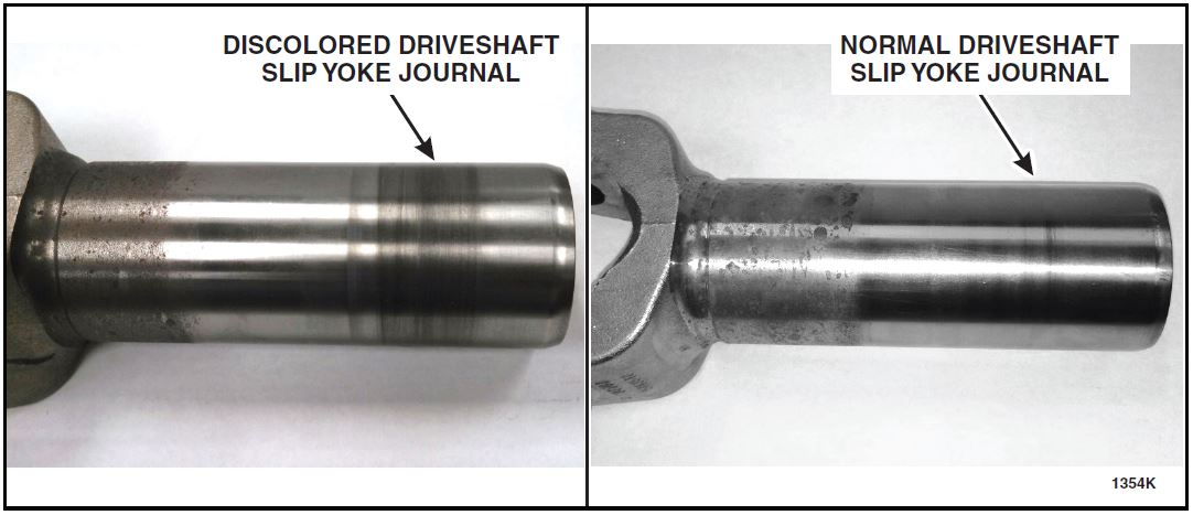
- If vehicle mileage is 20 km (12 mi) or less, visually inspect the driveshaft slip yoke journal for
discoloration and/or bushing material transfer. See Figure 1. - If Vehicle mileage is 21 km (13 mi) or more, or if discoloration and/or bushing material transfer is evident, discard the extension housing and replace the driveshaft slip yoke and universal joint. For additional information, refer to WSM Section 205-01. Once completed, proceed to Step 4.
FIGURE 1
- NOTICE: When supporting the transmission output shaft, use a rubber pad or block of wood to prevent damage to the shaft.
Support the rear of the transmission output shaft with a jack stand and remove the transmission jack that was positioned in Step 2.
- On vehicles equipped with a gasoline engine, remove the exhaust Y-Pipe. For additional information, refer to WSM Section 309-00.
- Remove the fl uid pan, gasket, and fi lter. For additional information refer to WSM Section 307-01B.
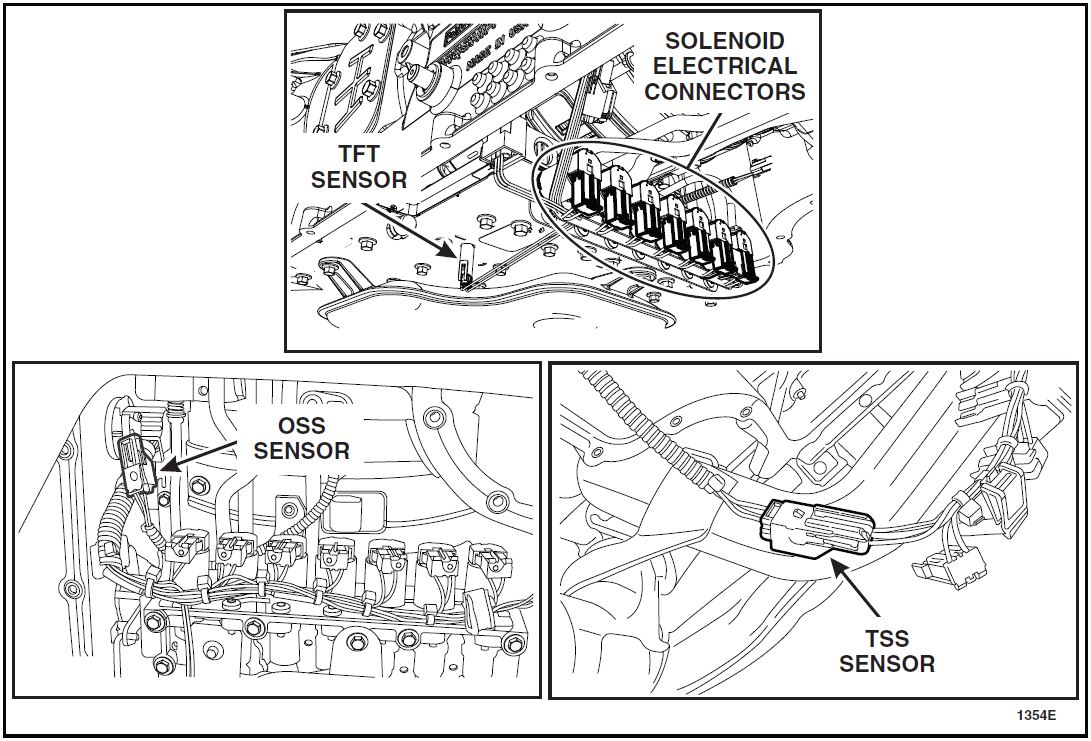
- Disconnect the seven solenoid electrical connectors, Transmission Fluid Temperature (TFT) Sensor, Output Shaft Speed (OSS) sensor, and Turbine Shaft Speed (TSS) sensor. Position the wiring harness aside. See Figure 2.
FIGURE 2
- NOTICE: Do not bend the manual valve rod clip when removing the manual valve rod. If the manual valve rod clip is bent back to remove the manual valve rod instead of sliding it off, the manual valve rod clip will become permanently distorted causing total loss of transmission control or transmission failure. If the manual valve rod clip is bent, install a new manual valve rod clip.
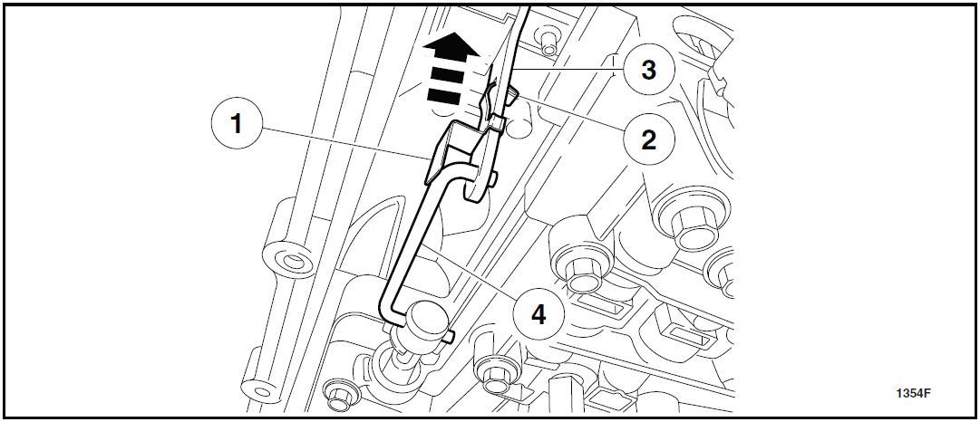
Remove the manual valve rod. Pull the manual valve rod clip tab out of the Transmission Range (TR) sensor, slide the manual valve rod clip off of the manual valve rod and remove the manual valve rod from the TR sensor and the manual valve. See Figure 3.
1. Manual valve rod clip
2. Manual valve rod clip tab
3. TR sensor
4. Manual valve rod
FIGURE 3
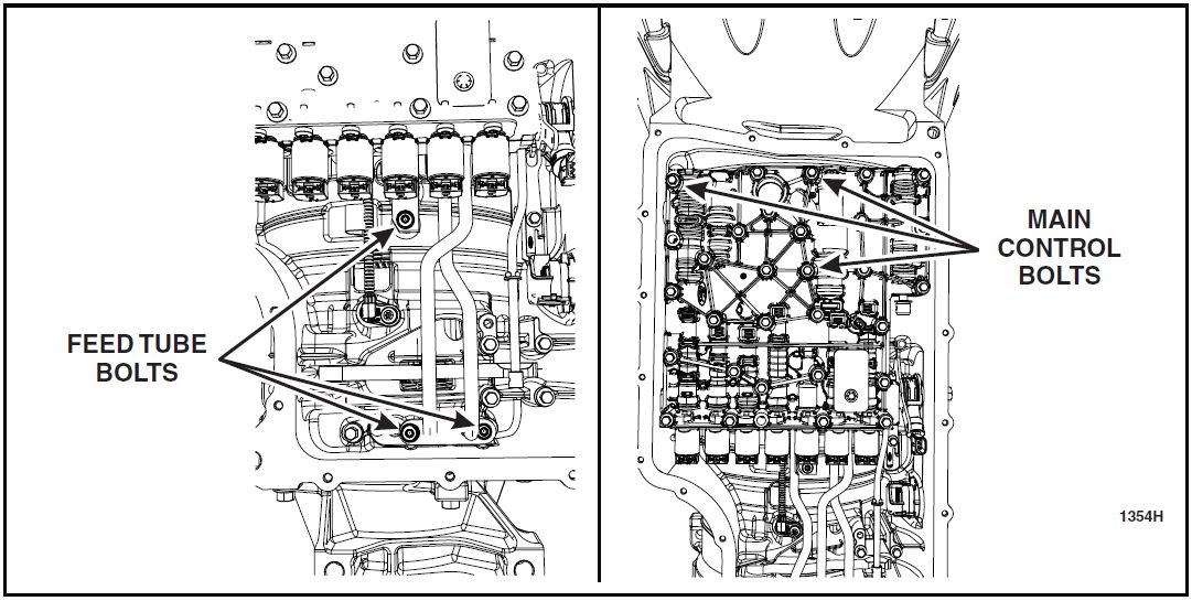
- Remove the 3 feed tube bolts, 3 main control bolts and remove the main control and feed tube assembly. See Figure 4.
FIGURE 4
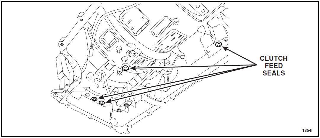
- NOTICE: Note the ports where the feed seals are removed from. Failure to install the feed seals in the ports they were removed from can result in pressure loss and transmission failure.
Remove the 4 clutch feed seals. See Figure 5.
FIGURE 5
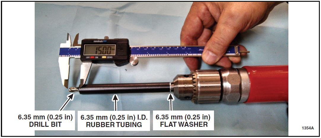
- NOTE: Materials needed for drill stop:
Set up drill stop to drill 15 mm (0.6 in) depth using a fl at washer and rubber tubing. See Figure 6.
a. Chuck bit securely
b. Slide fl at washer onto drill bit against drill chuck.
c. Push rubber tubing onto drill bit.
d. Measure 15 mm (0.6 in) from the tip of the drill bit and mark rubber tubing.
e. Remove the rubber tubing from the drill bit and cut to length.
f. Reinstall the rubber tubing and verify 15 mm (0.6 in) of the drill bit is exposed.
FIGURE 6
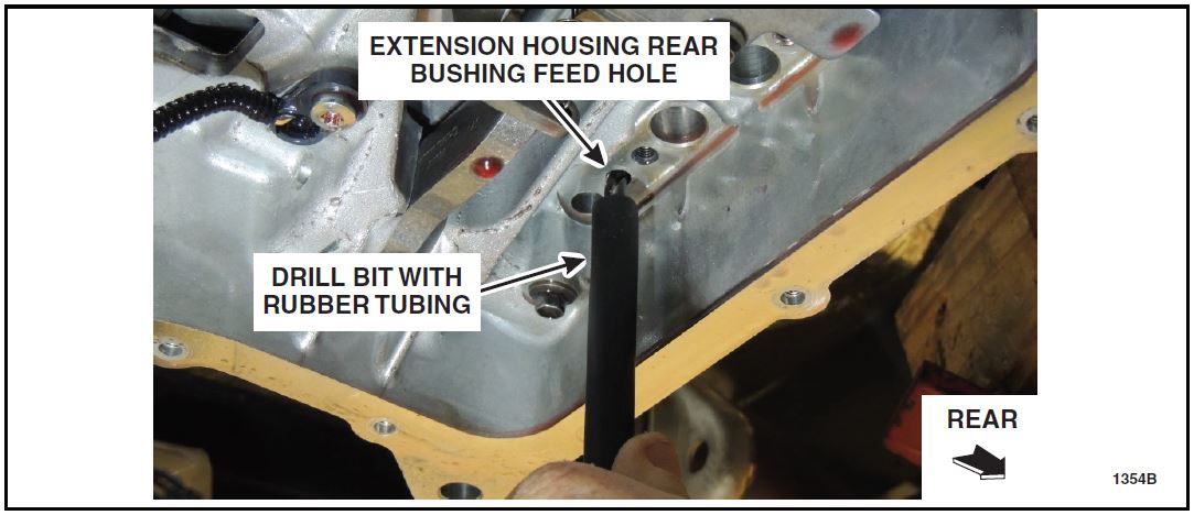
- Locate and begin drilling the case to extension housing rear bushing feed hole until the rubber tube contacts the case. Remove and clear any debris from the tool and repeat the drilling process to confirm the passage to the extension housing bushing has been opened. Note that the passage to the bushing is smaller than the 6.35 mm (0.25 in) hole feeding it. See Figure 7.
FIGURE 7
NOTICE: Compressed air and/or aerosol solvent should ONLY be introduced through the rear of the transmission fluid feed and return passages when cleaning out debris.
Damage will occur if passages are flushed from the main control side.
- Blow compressed air from the rear of the transmission case ONLY to clear the passage.
- If the passage IS clear, continue to Step 14.
- If the passage IS NOT clear, verify that 15 mm (0.6 in) of the drill stop is set correctly and repeat Step 12.
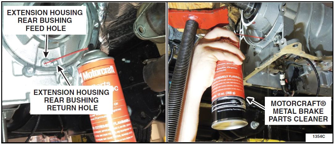
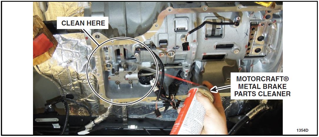
- Flush the feed and return passages from the rear of the transmission case ONLY using Motorcraft Metal Brake Parts Cleaner PM-4-A. Use compressed air to aid in clearing any remaining contamination or debris. See Figure 8.
FIGURE 8
- Flush the inside of the transmission case near the drilling area to clear any remaining debris using Motorcraft Brake Parts Cleaner PM-4-A. Do not spray directly into the drilled passage from this direction. See Figure 9.
FIGURE 9
- Lubricate the clutch feed seals and install them in the transmission. See Figure 5.
- NOTE: The three long bolts secure the valve body and the three short bolts secure the feed tubes.
Position the main control in place and install the 3 main control bolts and the 3 feed tube bolts.
See Figure 4.
- Tighten bolts to 11 Nm (97 lb-in).
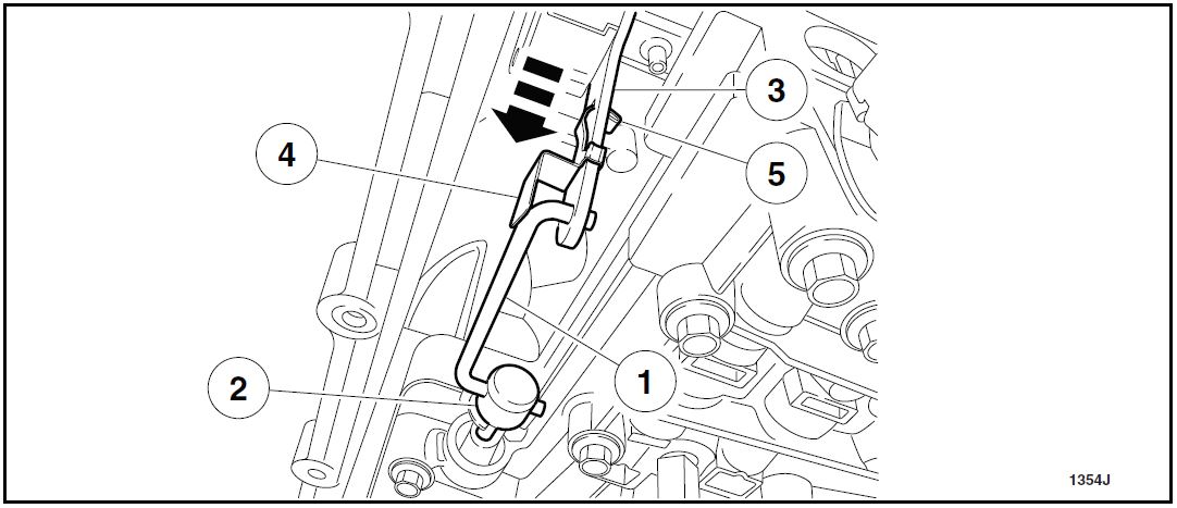
- NOTICE: Do not bend the manual valve rod clip when removing the manual valve rod. If the manual valve rod clip is bent back to remove the manual valve rod instead of sliding it off, the manual valve rod clip will become permanently distorted causing total loss of transmission control or transmission failure. If the manual valve rod clip is bent, install a new manual valve rod clip.
Install the manual valve rod in the manual valve and the TR sensor and move the manual valve rod clip over the manual valve rod until the manual valve rod clip tab goes through the TR sensor to hold the manual valve rod in place. See Figure 10.
1. Manual valve rod
2. Manual valve
3. TR sensor
4. Manual valve rod clip
5. Manual valve rod clip tab
FIGURE 10
- Position the wiring harness in place and connect the seven solenoid electrical connectors, Transmission Fluid Temperature (TFT) Sensor, Output Shaft Speed (OSS) sensor, and Turbine Shaft Speed (TSS) sensor. See Figure 2.
- NOTE: Before installing the transmission pan, add XL-16 ATF Additive directly into the pan.
NOTE: Do not perform the transmission fluid fill procedure at this time.
Install the fluid pan, gasket, and filter. For additional information refer to WSM Section 307-01B.
- On vehicles equipped with a gasoline engine, install the exhaust Y-Pipe. For additional information, refer to WSM Section 309-00.
- Temporarily support the transmission with a suitable heavy duty transmission jack.
- Place the jack so the fl uid pan does not support the weight of the transmission.
- Remove the jack stand that was positioned in Step 4.
- NOTE: If the extension housing does not require replacement, inspect the O-ring seal and replace only if damaged.
Install the transmission extension housing, cross member, and driveshaft. For additional information, refer to WSM Section 307-01B.
- Remove the transmission jack.
- Perform transmission fluid fill procedure. For additional information refer to WSM Section 307-01B.
- Return the vehicle to the customer.
December 2013
Customer Satisfaction Program 13B11
Programa de Satisfacción del Cliente 13B11
Mr. John Sample
123 Main Street
Anywhere, USA 12345
Your Vehicle Identification Number: 12345678901234567
At Ford Motor Company, it has been our goal for more than 100 years to provide customers with high-quality, dependable products. In order to maintain these standards, Ford
 Motor Company is providing a no-charge Customer Satisfaction Program (Program Number 13B11) for your vehicle, with the Vehicle Identification Number shown above.
| What is the issue? | On your vehicle, a passage in the transmission case that provides lubrication to the driveshaft slip yoke bushing may not be present. A lack of fluid at the driveshaft slip yoke bushing will result in noise, vibration, and premature wear of the extension housing bushing and driveshaft slip yoke. |
What will Ford and your dealer do? and your dealer do? | In the interest of customer satisfaction, Ford Motor Company has authorized your dealer to repair your transmission free of charge (parts and labor) under the terms of this program. Motor Company has authorized your dealer to repair your transmission free of charge (parts and labor) under the terms of this program.
This Customer Satisfaction Program will be in effect until May 31, 2014 regardless of mileage. Coverage is automatically transferred to subsequent owners. |
| How long will it take? | The time needed for this repair is less than one-half day. However, due to service scheduling requirements, your dealer may need your vehicle for a longer period of time. |
| What should you do? | Please call your dealer without delay and request a service date for
Customer Satisfaction Program 13B11. Provide the dealer with the Vehicle Identification Number (VIN) of your vehicle. The VIN is printed near your name at the beginning of this letter. If you do not already have a servicing dealer, you can access www.Fordowner.com for dealer addresses, maps, and driving instructions. Ford |
| What if you no longer own this vehicle? | If you no longer own this vehicle, and have an address for the current owner, please forward this letter to the new owner.
You received this notice because our records, which are based primarily on state registration and title data, indicate that you are the current owner. |
| Can we assist you further? | If you have difficulties getting your vehicle repaired promptly and without charge, please contact your dealership’s Service Manager for assistance.
RETAIL OWNERS: If you still have concerns, please contact the Ford Motor Company Customer Relationship Center at 1-866-436-7332 and one of our representatives will be happy to assist you. For the hearing impaired call 1-800-232-5952 (TDD). Representatives are available Monday through Friday: 8:00AM – 5:00PM (Your Local Time). If you wish to contact us through the Internet, our address is: www.Fordowner.com. Si necesita ayuda o tiene alguna pregunta, por favor llame al Centro de Relación con Clientes al 1-866-436-7332 y presione 2 para Español. FLEET OWNERS: If you still have concerns, please contact the Fleet Customer Information Center at 1-800-34-FLEET, Option #3 and one of our representatives will be happy to assist you. Representatives are available Monday through Friday: 8:00AM – 5:00PM (Your Local Time). Or you may contact us through the Internet at www.fleet.ford.com. |
Thank you for your attention to this important matter.
Ford Customer Service Division
 Loading...
