| “This site contains affiliate links for which OEMDTC may be compensated” |
June 17, 2013
TO: All U.S.Ford and Lincoln Dealers
SUBJECT: DELIVERY HOLD – Customer Satisfaction Program 13B02 – Supplement #1
Certain 2013 Model Year Fusion Vehicles Equipped with a Moon Roof
Headliner Wrinkles
REF: DELIVERY HOLD – Customer Satisfaction Program 13B02
Headliner Wrinkles dated April 2, 2013
New! REASON FOR THIS SUPPLEMENT
- The Technical Instructions in Attachment III have been modified to further optimize the repair procedure. (Note: This procedure is unique from the Workshop Manual procedure)
- Based upon the amount of related damage dealers are encountering while performing this repair (e.g., trim panels damaged during removal and trim retention clips remaining in the sheetmetal), the guidelines for claiming related damage have been revised as follows:
- Dealers are authorized to claim replacement of trim panels damaged during removal as Related Damage without contacting the Special Service Support Center for authorization.
- Dealers are authorized to claim up to an additional 0.5 hour in related damage labor for the removal of trim panel clips from the sheetmetal without contacting the Special Service Support Center for authorization.
- The Labor Operations and Claiming Instructions in Attachment II have been revised accordingly.
PROGRAM TERMS
This program will be in effect through April 30, 2014. There is no mileage limit for this program.
AFFECTED VEHICLES
Certain 2013 model year moon roof equipped Fusion vehicles built at the Hermosillo Assembly Plant from February 7, 2012 through November 1, 2012. Affected vehicles are identified in OASIS. In addition, for a list of vehicles assigned to your dealership, visit https://web.fsavinlists.dealerconnection.com. This information was available on April 2, 2013.
REASON FOR THIS PROGRAM
Differing rates of thermal expansion exist between the headliner substrate, glue, and other components bonded to the backside of the headliner, which can result in a wrinkle condition around the moon roof opening. Note that the wrinkle condition is accentuated by high and low ambient temperature cycles.
SERVICE ACTION
Before delivering any of the vehicles involved in this program, dealers are to replace or modify the headliner based upon the following criteria:
- For vehicles built on or before October 10, 2012, the headliner must be replaced.
- For vehicles built on or after October 11, 2012, dealers must inspect the headliner for the presence of wrinkles around the moon roof opening (see Attachment III).
- If wrinkles are present, the headliner must be replaced.
- If wrinkles are not present, the headliner must be modified to prevent wrinkles from occurring in the future. The modification involves lowering the headliner and cutting reliefs into the blocks and supports glued to the backside of the headliner. The relief cuts allow the components to expand and contract without wrinkling the headliner material.
NOTE: Headliners are extraordinarily large and, as a result, shipping time to dealers may be longer than usual. Please take the extended shipping time into consideration when scheduling service appointments.
OWNER NOTIFICATION MAILING SCHEDULE
Owner Letters were mailed in April, 2013. Dealers should repair any affected vehicles that arrive at their dealerships, whether or not the customer has received a letter.
New! ATTACHMENTS
Attachment I: Administrative Information
Attachment II: Labor Allowances and Parts Ordering Information
Attachment III: Technical Information
Owner Notification Letter
QUESTIONS & ASSISTANCE
Special Service Support Center (Dealer Assistance Only)……..1-800-325-5621
Special Service Support Center (Parts Ordering)…….1-800-207-2444
Sincerely,
Michael A. Berardi
ATTACHMENT I
DELIVERY HOLD – Customer Satisfaction Program 13B02 – Supplement #1
Certain 2013 Model Year Fusion Vehicles Equipped with a Moon Roof
Headliner Wrinkles
OASIS ACTIVATED?
Yes, OASIS was activated on April 2, 2013.
New! FSA VIN LIST ACTIVATED?
Yes, FSA VIN list was available through https://web.fsavinlists.dealerconnection.com on April 2, 2013. Owner names and addresses will be available in June, 2013.
NOTE: Your FSA VIN list may contain owner names and addresses obtained from motor vehicle registration records. The use of such motor vehicle registration data for any purpose other than in connection with this program is a violation of law in several states, provinces, and countries. Accordingly, you must limit the use of this listing to the follow-up necessary to complete this service action.
STOCK VEHICLES
- Correct all affected units in your new vehicle inventory before delivery.
- Use OASIS to identify any affected vehicles in your used vehicle inventory.
SOLD VEHICLES
- Owners of affected vehicles will be directed to dealers for repairs.
- Immediately contact any of your affected customers whose vehicles are not on your VIN list but are identified in OASIS. Give the customer a copy of the Owner Notification Letter (when available) and schedule a service date.
- Correct other affected vehicles identified in OASIS which are brought to your dealership.
TITLE BRANDED / SALVAGED VEHICLES
Affected title branded and salvaged vehicles are eligible for this service action.
New! RELATED DAMAGE
Dealers are authorized to: o Claim the replacement of trim panels damaged during removal as Related Damage without contacting the Special Service Support Center for authorization.
- Claim up to an additional 0.5 hour in related damage labor time for the removal of trim panel clips from the sheetmetal without contacting the Special Service Support Center for authorization.
If a related damage condition exists as a result of performing this repair that exceeds the amounts stated above, call the Special Service Support Center to request approval prior to repairing the incremental damage. Requests for approval after completion of the repair will not be granted.
ADDITIONAL LABOR TIME
If you encounter aftermarket equipment or modifications to the vehicle which might prevent the repair of the covered condition, call the Special Service Support Center.
OWNER REFUNDS
Refunds are not authorized for this program.
RENTAL VEHICLES
The use of rental vehicles is not authorized for this program.
New! CLAIMS PREPARATION AND SUBMISSION
- Enter claims using Direct Warranty Entry (DWE).
- Refer to ACESII manual for claims preparation and submission information.
- Related damage must be claimed as “MT13B02” on a repair line that is separate from the repair line on which the FSA is claimed with the Related Damage flag checked. Prior approval is not required unless the related damage exceeds 0.5 hours labor. Related damage in excess of this amount requires prior approval from the Special Service Support Center.
- PROGRAM TERMS: This program will be in effect through April 30, 2014. There is no mileage limit for this program.
- Provision for Locally Procured 3M Super-Fast Repair Adhesive 04747: Includes specified adhesive. Submit on the same repair line as the repair.
- Program Code: 13B02
- Expense: OTHER
- Expense: Claim Actual Cost up to $30.00
- Provision for Special Tool – Locally Procured Dremel Bit: A special Tungsten Carbide cutter bit is required for performing the headliner modification. Dealers will be reimbursed for the cost of one Dremel 9903 Tungsten Carbide Bit. For reimbursement, the actual cost of the bit tool must be submitted on one of the initial claims for this FSA.
- Program Code: 13B02
- Expense: TOOL
- Expense: Claim Actual Cost up to $20.00
NOTE: One Tungsten Carbide Bit (Cutter) per dealer can be claimed.
ATTACHMENT II
DELIVERY HOLD – Customer Satisfaction Program 13B02 – Supplement #1
Certain 2013 Model Year Fusion Vehicles Equipped with a Moon Roof
Headliner Wrinkles
New! LABOR ALLOWANCES
| Description | Labor Operation | Labor Time* |
| Replace Headliner (Vehicles built on or before 10/10/12) Includes time to transfer headliner components. | 13B02B | 3.6 Hour(s) |
| Inspect and Replace Headliner (Vehicles built on or after
10/11/12) Includes time to transfer headliner components. | 13B02C | 3.6 Hour(s) |
| Inspect and Modify Headliner (Vehicles built on or after 10/11/12) | 13B02D | 2.6 Hour(s) |
* Labor times have been updated based upon the optimized repair procedure – See Attachment III
PARTS REQUIREMENTS / ORDERING INFORMATION
| Part Number | Description | Quantity |
| DS7Z-5451916-BA | Headliner-Light Dune | 1 |
| DS7Z-5451916-BB | Headliner-Light Grey | 1 |
| DS7Z-5451916-HA | Headliner-Light Dune (Electrified vehicles) | 1 |
| DS7Z-5451916-HB | Headliner-Light Grey (Electrified vehicles) | 1 |
| 04747 | 3M Super-Fast Repair Adhesive, 04747 | 1 (Obtain Locally) |
The DOR/COR number for this recall is 50501.
To manage availability of the parts listed above, dealers must contact the Special Service Support Center Parts Order Line at 1-800-207-2444.
When calling to place an order for a headliner, please be prepared to provide dealer P&A code, VIN, and RO #.
Dealers will be notified via a DOES II communication if circumstances warrant a change in part supply strategy and when open ordering resumes.
REQUIRED SPECIAL TOOLS
To perform the headliner modification, a special Dremel 9903 Tungsten Carbide Bit (Cutter) is required, for reimbursement, see Claims Preparation and Submission in Attachment I.
DEALER PRICE
For latest prices, refer to DOES II.
PARTS RETENTION AND RETURN
Affected parts are subject to random selection for return to the Ford Warranty Parts Analysis Center (WPAC). Refer to your daily PEARS (Parts Entry and Return System) register for part disposition and return instructions.
Follow the provisions of the Warranty and Policy Manual for “Parts Retention and Return Procedures.”
EXCESS STOCK RETURN
Excess stock returned for credit must have been purchased from Ford Customer Service Division in accordance with Policy Procedure Bulletin 4000.
ATTACHMENT III
CERTAIN 2013 MODEL YEAR FUSION VEHICLES EQUIPPED WITH A MOON ROOF
— HEADLINER WRINKLES
OVERVIEW
Before delivering any of the vehicles involved in this program, dealers are to replace or modify the headliner for wrinkles based upon the following criteria:
- For vehicles built on or before October 10, 2012, the headliner must be replaced.
- For vehicles built on or after October 11, 2012, dealers must inspect the headliner for the presence of wrinkles around the moon roof opening to determine if the headliner must be modified or replaced.
INSPECTION
For vehicles built on or after October 11, 2012, dealers must inspect the headliner for the presence of wrinkles around the moon roof opening to determine if the headliner must be modified or replaced.
See Figure 1.
- If wrinkles are present, the headliner must be replaced.
- If wrinkles are not present, the headliner must be modified to prevent wrinkles from occurring in the future. The modification involves lowering the headliner and cutting reliefs into the blocks and supports glued to the backside of the headliner. The reliefs allow the components to expand and contract and at different rates without wrinkling the headliner material.

FIGURE 1
SERVICE PROCEDURE
NOTE: The headliner Removal and Installation procedure has been optimized within this supplement for improved serviceability, reduced potential for interior trim damage, and clarification of the optimal seat position for ease of headliner removal and installation.
NOTE: When removing trim panels, the retaining clips may remain engaged in the vehicle sheet metal.
Using a pair of needle nose pliers, compress the inner tabs of the clip and pull back to remove.
If there is no damage to the trim panel or clip, reinstall the clip onto the trim panel. See Figure 2.

FIGURE 2
Removal
Vehicles Equipped with Rain Sensitive Wipers and/or Auto Dimming Mirror
- Disconnect the battery ground cable. For additional information, refer to Workshop Manual (WSM) Section 414-01.
- Remove the glove compartment. For additional information, refer WSM Section 501-12.
- Disconnect the rain sensor and/or auto dimming mirror electrical connectors. See Figure 3.
NOTE: Rain sensor electrical connector shown, auto dimming mirror electrical connector similar.

FIGURE 3
All Vehicles
- NOTE: If the vehicle is equipped with rain sensitive wipers and/or auto dimming mirror the RH Instrument Panel (IP) side trim panel will have been removed previously.
Remove the RH and LH IP side trim panels. See Figure 4.
NOTE: RH side shown, LH side similar.

FIGURE 4
- Remove the RH and LH lower A-pillar trim panels. See Figure 5.
NOTE: RH side shown, LH side similar.

FIGURE 5
- Partially remove the upper RH and LH A-pillar trim panels leaving the forward clip engaged. Secure the trim panels to the windshield with tape. See Figure 6.
NOTE: Tape A-pillar trim panel to the windshield as indicated in Figure 6 to reduce the stress in the area around the forward clip attachment.
NOTE: RH side shown, LH side similar.

FIGURE 6
NOTE: Note the position of the vehicle seats, so that they can be returned to the customers original position once the repair is complete.
- NOTE: Only connect the negative battery cable to temporarily restore vehicle power, do not re-install battery hold down or torque the battery cable at this time.
Connect the battery ground cable. - Position the RH and LH front seats to their full forward position.
- Disconnect the battery ground cable.
- Remove the RH and LH front and rear door opening sill plates.
- Remove the RH and LH lower B-pillar trim panels.
- Remove the safety belt D-ring cover and bolt from the RH and LH upper B-pillar. See Figure 7.
Position the safety belts away from the upper B-pillars.
NOTE: RH side shown, LH side similar.

FIGURE 7
- Remove the bolts and the RH and LH upper B-pillar trim panels. See Figure 8.
NOTE: RH side shown, LH side similar.

FIGURE 8
- Fold the RH and LH rear seat back down.
- Position the rear safety belt away from the RH and LH lower C-pillar trim panels. Starting from the top, pull to release the clips and remove the RH and LH lower C-pillar trim panels.
NOTICE: Do not separate the RH and LH D-pillar trim panels from the upper C-pillar trim panels. They should be removed as an assembly to prevent damage to the retaining clips.
- Remove the RH and LH upper C-pillar and D-pillar trim panels together. See Figure 9 and 10.
- Position the safety belt out of the opening in the RH and LH upper C-pillar trim panels.
- Remove the RH and LH upper C-pillar and D-pillar trim panels by pulling to release the retaining clips.
NOTE: The upper C-pillar and D-pillar trim panels are difficult to remove. Using a trim removal tool like the one shown in Figure 10 to release the clips will aid in the removal process.
NOTE: RH side shown, LH side similar.

FIGURE 9

FIGURE 10
- NOTE: Only connect the negative battery cable to temporarily restore vehicle power, do not re-install battery hold down or torque the battery cable at this time.
Connect the battery ground cable.
- NOTE: Both front seats must be positioned to the full rearward and reclined position or you will not be able to remove the headliner through the passenger front door.
Position the RH and LH rear seat backs up, and then the RH and LH front seats to the full rearward and reclined position.
- Disconnect the negative battery cable.
NOTE: Steps 20-28 are only required if the headliner is being removed for replacement. If replacement is not required, skip to step 29 on Page 12.
- NOTE: The BCM removal and installation procedure has been updated in the Workshop Manual.
Remove the Body Control Module (BCM). For additional information, refer to WSM Section 419-10.
- NOTE: The use of an 18 inch, 1/4 drive extension between the steering column opening trim panel and lower steering column shroud will aid in the removal of the BCM mounting bracket nuts.
See Figure 11.
Position aside the BCM mounting bracket by removing the three bracket nuts. Only position aside far enough to access the electrical connector behind the bracket. See Figure 11.

FIGURE 11
- Disconnect the headliner electrical connector (closest to the LH front door opening) behind the BCM mounting bracket. See Figure 12.

FIGURE 12
- Remove the floor console. For additional information, refer to WSM Section 501-12.
Vehicles With Manual Transmission
- Remove the shift cables from the gearshift lever. See Figure 13.

FIGURE 13
- Remove the four bolts and the gearshift lever. See Figure 14.

FIGURE 14
Vehicles With Automatic Transmission
- Disconnect the selector lever cable end from the selector lever. See Figure 15.

FIGURE 15
- Remove the bolt from the selector lever cable retaining bracket. Remove the bracket and position the selector lever cable aside. See Figure 16.

FIGURE 16
- Disconnect the selector lever electrical connector. Remove the four bolts and remove the selector lever. See Figure 17.

FIGURE 17
All Vehicles
- If equipped, remove the rear view mirror trim. See Figure 18.

FIGURE 18
- If equipped, disconnect the rain sensor and/or auto dimming mirror electrical connectors behind the rear view mirror.
- Remove the RH and LH sunshade (visor) from the vehicle.
- Remove the clip cover and remove the clip. Disconnect the electrical connector from the RH and LH sunshades.
- Remove the RH and LH sunshade hooks.
- Remove the screw from each hook and remove the RH and LH hooks.
- Remove the four assist handles.
- Using a small non-marring plastic trim tool, expose the fasteners by removing the fastener covers. Remove the fasteners from each handle and remove all handles.
- Disconnect the five headliner wire harness to body retainers along the LH A-pillar. If equipped, disconnect the five rain sensor and/or auto dimming mirror wire harness to body retainers from the RH A-pillar. See Figure 19. Carefully route both wire harnesses up through the instrument panel.
NOTE: LH side shown, RH side similar.

FIGURE 19
- Lower the headliner by pulling downward to release the nine magnets and two guide pins. If headliner replacement is not required, proceed to “Headliner Modification Procedure” on Page 16.
Headliner Replacement
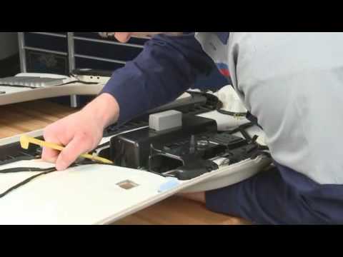
- With the help of an assistant, remove the headliner through the front passenger side door.
See Figure 20. Click here for headliner removal instruction video (removal shown, installation similar).

FIGURE 20
- NOTICE: Special care needs to be taken while removing the overhead console. The rear attachment retaining tabs are extremely fragile. See Figure 21a and 21b.
Click here for overhead console removal instruction video.
Remove the overhead console from the headliner. See Figure 21a and 21b (headliner cutaway view shown for clarity).
- Disengage the rear overhead console attachments by pushing up on the console from the interior side while holding the headliner bracket in place. Slowly press the retaining tab inboard to release.
- Support the overhead console from the interior side and use a set of pliers to release the middle retaining tabs.
- Pry down gently to free the overhead console. Rotate the rear of the console downward to access the electrical connectors.
- Disconnect and remove the overhead console.

FIGURE 21a

FIGURE 21b
NOTE: The 3M Super-Fast Repair Adhesive (04747) will set in 20 seconds. Continually make sure that the wire harness is routed correctly when applying adhesive. The use of masking tape to temporarily hold the harness in position while applying the adhesive will aid in proper installation of the wire harness.
- Transfer the wire harness in the following sequence:
- Using a suitable marking tool, mark the new headliner with the routing and exit points of the wire harness from the original headliner.
- Carefully remove the wire harness from the original headliner.
- Position the wire harness onto the new headliner and check that the harness has enough length to make all connections.
- Apply the 3M Super-Fast Repair Adhesive (04747) in the same location as the factory installed adhesive along the full length of the wire harness-to-headliner.
- Transfer the rear interior lamp, Radio Transceiver Module (RTM) and brackets to the new headliner. See Figure 22.

FIGURE 22
- Install the overhead console into the new headliner:
- Connect the overhead console electrical connectors.
- Insert the front portion of the overhead console first and then bring the rear of the console flush with the headliner.
- Push evenly on both sides of the console to engage the console clips. Engage the middle console clips, followed by the front clips, and lastly the rear clips.
Headliner Modification Procedure
NOTE: If the headliner is being replaced, skip to “Headliner Installation” on Page 17, no modification is necessary.
NOTE: Modification of the headliner reinforcements will prevent wrinkles by allowing greater flexibility of the substrate material.
- Mark cut locations on the headliner reinforcement material. See Figure 23.

FIGURE 23
NOTICE: When cutting headliner reinforcements, care must be taken not to cut any deeper than the reinforcement material. Cutting deeper than the reinforcement material can result in damage to the headliner. Holding the DREMEL cutting tool at a 45 degree angle will help ensure a smoother cut and reduce the risk of cutting deeper than necessary.
- Using a DREMEL tool with bit (part # 9903), cut the plastic reinforcements following the previously marked locations. See Figure 24.
 FIGURE 24
- Using a shop vacuum, clean the vehicle of any debris created during headliner modification.
Headliner Installation
NOTE: Step 1 is only required if the headliner has been removed for replacement.
- With the help of an assistant, install the headliner through the front passenger side door, reversing direction from the removal instruction video. See Figure 20.
- Raise the headliner and engage the nine magnets and two guide pins.
- Carefully route the headliner and rain sensor/auto dimming mirror wire harnesses down through the instrument panel. Connect the five headliner wire harness to body retainers along the LH A-pillar. If equipped, connect the five rain sensor and/or auto dimming mirror wire harness to body retainers to the RH A-pillar. See Figure 19.
- Install all four assist handles.
- Install the RH and LH sunshade hooks.
- Tighten fasteners.
- Install the RH and LH sunshades.
- Connect the electrical connector. Install the clip and clip cover.
- If equipped, connect the rain sensor and/or auto dimming mirror electrical connectors behind the rear view mirror.
- If equipped, install the rear view mirror trim. See Figure 18.
NOTE: Steps 9-17 are only required if the headliner has been removed for replacement. If replacement was not required, proceed to Step 18 below.
Vehicles With Automatic Transmission
- Install the selector lever and tighten the four bolts. Connect the selector lever electrical connector. See Figure 17.
- Tighten selector lever bolts to 9 Nm (80 lb-in).
- Reposition the selector lever cable and install the retaining bracket. See Figure 16.
- Tighten cable retaining bracket bolt to 7 Nm (62 lb-in).
- Connect the selector lever cable end from the selector lever. See Figure 15.
Vehicles With Manual Transmission
- Install the gearshift lever and tighten the four bolts. See Figure 14.
- Tighten gearshift lever bolts to 9 Nm (80 lb-in).
- Install the shift cables onto the gearshift lever. See Figure 13.
All Vehicles
- Install the floor console. For additional information, refer to WSM Section 501-12.
- Connect the headliner electrical connector behind the BCM mounting bracket location.
See Figure 12. - Reposition the BCM mounting bracket. Install and tighten the three bracket nuts. See Figure 11.
- Install the Body Control Module (BCM). For additional information, refer to WSM Section 419-10.
- NOTE: Only connect the negative battery cable to temporarily restore vehicle power, do not re-install battery hold down or torque the battery cable at this time.
Connect the battery ground cable.
- Position the RH and LH front seats to the full forward and upright position, and position the RH and LH rear seat back downward.
- Disconnect the battery ground cable.
- Install the RH and LH upper C-pillar and D-pillar trim panels. See Figure 9 and 10.
- Reposition the safety belts into the opening in the C-pillar upper trim panels.
- Install the RH and LH lower C-pillar trim panels and engage the clips.
- Reposition the safety belts back to the lower C-pillar trim panels.
- Position the RH and LH rear seat back up.
- Install the RH and LH upper B-pillar trim panels and install the bolts. See Figure 8.
- Tighten upper B-pillar trim panel bolts to 9 Nm (80 lb-in).
- Reposition the RH and LH safety belts to the upper B-pillars and install the D-ring bolts.
See Figure 7.- Tighten D-ring bolts to 40 Nm (30 lb-ft) and install the safety belt D-ring covers.
- Install the RH and LH lower B-pillar trim panels.
- Install the RH and LH front and rear door opening sill plates.
- Connect the battery ground cable. For additional information, refer to Workshop Manual (WSM)
Section 414-01. - Position the vehicle seats back to the customers original position.
- Remove the tape and position back the RH and LH upper A-pillar trim panels. See Figure 6.
- Install the RH and LH lower A-pillar trim panels. See Figure 5.
Vehicles Equipped with Rain Sensitive Wipers and/or Auto Dimming Mirror
- Connect the rain sensor and/or auto dimming mirror electrical connectors. See Figure 3.
- Install the glove compartment. For additional information, refer to WSM Section 501-12.
All Vehicles
- Install the RH and LH IP side trim panels. See Figure 4.
- Return the vehicle to the customer.
April 2013
Customer Satisfaction Program 13B02
Mr. John Sample
123 Main Street
Anywhere, USA 12345
Your Vehicle Identification Number: 12345678901234567
We hope you are enjoying the many great attributes of your new 2013 Fusion! At Ford Motor Company, it has been our goal for more than 100 years to provide our customers with products they fully enjoy. In order to maintain these standards, Ford Motor Company is providing a no-charge Customer Satisfaction Program (Program Number 13B02) for your vehicle, with the Vehicle Identification Number shown above.
| What needs to be updated? | It may be possible that wrinkles could develop on the interior headliner of your vehicle around the moon roof opening. |
| What will Ford and your dealer do? | In the interest of customer satisfaction, Ford Motor Company has authorized your dealer to inspect the headliner in your vehicle and either replace or modify it based upon the results of the inspection. This service will be performed free of charge (parts and labor) under the terms of this program.
This Customer Satisfaction Program will be in effect until April 30, 2014 regardless of mileage. Coverage is automatically transferred to subsequent owners. |
| How long will it take? | The time needed for this repair is less than one-half day. However, due to service scheduling requirements, your dealer may need your vehicle for a longer period of time. Calling your dealer in advance will help ensure that parts are available when you arrive. Please note that, depending on the date that your vehicle was produced, your dealer may need to inspect the headliner in your vehicle before parts can be ordered. |
| What should you do? | Please call your dealer without delay and request a service date for Customer Satisfaction Program 13B02. Simply provide the dealer with the Vehicle Identification Number (VIN) of your vehicle and they will prepare for the updates you need. The VIN is printed near your name at the beginning of this letter.
If you do not already have a servicing dealer, you can access www.Fordowner.com for dealer addresses, maps, and driving instructions. |
| What if you no longer own this vehicle? | If you no longer own this vehicle, and have an address for the current owner, please forward this letter to the new owner.
You received this notice because our records, which are based primarily on state registration and title data, indicate that you are the current owner. |
| Can we assist you further? | If you have difficulties getting your vehicle repaired promptly and without charge, please contact your dealership’s Service Manager for assistance.
RETAIL OWNERS: If you still have concerns, please contact the Ford Motor Company Customer Relationship Center at 1-866-436-7332 and one of our representatives will be happy to assist you. For the hearing impaired call 1-800-232-5952 (TDD). Representatives are available Monday through Friday: 8:00AM – 5:00PM (Your Local Time). If you wish to contact us through the Internet, our address is: www.Fordowner.com. FLEET OWNERS: If you still have concerns, please contact the Fleet Customer Information Center at 1-800-34-FLEET, Option #3 and one of our representatives will be happy to assist you. Representatives are available Monday through Friday: 8:00AM – 5:00PM (Your Local Time). Or you may contact us through the Internet at www.fleet.ford.com. |
Thank you for your attention to this important matter.
Ford Customer Service Division
 Loading...
