| “This site contains affiliate links for which OEMDTC may be compensated” |
| EXHAUST LEAK – CRACKED OR SEPARATED RIGHT SIDE EXHAUST PIPE – 3.8L AND 3.9L ENGINES |
FORD :
:

1999-2004 Mustang LX vehicles, equipped with a 3.8L or 3.9L engine may exhibit an exhaust leak.
This may be due to a cracked or fractured right side exhaust pipe, just forward of the first catalytic converter. This crack may be due to condensation dripping onto the pipe.
ACTION:
To service, order and install the appropriate Service Kit based on transmission type. The Kit contains a new inlet pipe, condensation shield and exhaust hanger.
SERVICE PROCEDURE
NOTE: ALL WELDS IN THIS REPAIR MUST BE MADE WITH 409 STAINLESS STEEL. OUTSOURCE WELDING AS NEEDED.
- Open hood and disconnect the battery cable.
- Raise the vehicle.
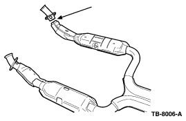
- Inspect the right side inlet pipe for a crack or separation just forward of the first catalyst (Figure 1).
- If the pipe is cracked, but is still in direct alignment with the rest of the pipe (has not shifted), go to the steps labeled “DIRECT ALIGNMENT”.
- If the pipe is misaligned or damaged, go to steps labeled “PIPE MISALIGNED OR DAMAGED”.
Figure 1
DIRECT ALIGNMENT
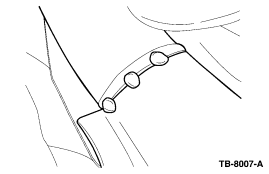
- Tack weld the inlet pipe to the catalyst in three (3) places (Figure 2).
Figure 2
- Remove the catalyst assembly from the vehicle.
- Remove the oxygen sensor near the area to be welded.
- Wire brush the end of the converter to prepare for the weld.
- Complete the weld with 409 stainless wire material.
- Proceed to the INSTALLATION OF THE AIR CONDITIONER DRIP SHIELD.
INSTALLATION OF THE AIR CONDITIONER DRIP SHIELD
- Loosen the bottom of the right front fender splash shield by removing the three (3) lower pushpin fasteners.
- FOR CONVERTIBLES ONLY; Remove the front attachment for the right side X-brace.
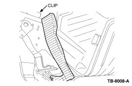
- Locate the air conditioner condensate discharge tube and install the air conditioner drip shield over it, by installing the clip on the shield over the upper frame rail located just below the air conditioner drier bottle (Figure 3).
Figure 3
NOTE: THE SHIELD MUST LIE AS CLOSE TO THE FLOOR PAN AS POSSIBLE.
- Lower the vehicle.
- Push the shield clip down onto the rail.
- Raise the vehicle.
- Attach the lower leg of the shield in an existing bolt hole using the bolt provided in the Kit.
- FOR CONVERTIBLES ONLY; Trap the shield between the X-brace and the cross member. Torque to 25 lb-ft (34 N-m).
- Reinstall the pushpin fasteners in the fender splash shield.
- Proceed to the INSTALLATION OF THE CATALYST HANGER.
INSTALLATION OF THE CATALYST HANGER TO THE TRANSMISSION
- For vehicles equipped with a manual transmission, remove the damper on the tailshaft housing of the transmission. Vehicles with an automatic transmission proceed to Step #2.
- Install the catalyst assembly.
- Support the rear of the assembly with a jack stand.
- Loosely tighten to the exhaust manifold.
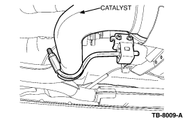
- Loosely install the hanger rod and U-clamp around the exhaust pipe near the “Y” of the catalyst (Figure 4).
- Slide the rubber isolator and bracket onto the rod with the bracket nuts facing the passenger side of the vehicle (Figure 4).
- Adjust the catalyst height and U-clamp so that the rubber isolator bracket will attach to the transmission extension housing (using the rearward holes – Figure 4).
Figure 4
- Install the two (2) bolts provided in the Kit and tighten to 18 lb-ft (25 N-m).
- Adjust the jack stand so the hanger rod is in the center of the isolator.
- Tighten the U-clamp fasteners to 29 lb-ft (40 N-m).
- Remove the jack stand.
- Tighten the catalyst to the exhaust manifold fasteners to 30 lb-ft (41 N-m).
- Attach the muffler inlet pipe and tighten to 26 lb-ft (35 N-m).
- Check the system for grounding.
- Lower the vehicle.
- Reconnect the battery.
- Start the engine and check for exhaust leaks.
PIPE MISALIGNED OR DAMAGED
NOTE: IF THE INLET PIPE IS NOT IN DIRECT ALIGNMENT OR WAS DAMAGED, INSTALL THE INLET PIPE PROVIDED IN THE KIT.
- Remove the catalyst assembly from the vehicle.
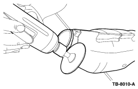
- The supplied inlet pipe will not fit into the catalyst shell until the small section of the old pipe is removed. To do this, start by placing a small shop rag into the pipe to keep dust and debris from entering into the catalyst.
- Cut around the exhaust tube (on the catalyst side of the weld) using a die grinder (Figure 5).
Figure 5
NOTE: CUT AS CLOSE TO THE WELD AS POSSIBLE. IT MAY BE NECESSARY TO TRIM NO MORE THAN A 1/4 INCH (6.5 MM) FROM THE END OF THE HEAT SHIELD FOR ADDITIONAL CLEARANCE.
- Grind the edge of the converter to remove the entire factory weld. This will allow the short section of the pipe to come out.
- Wire brush the end of the converter to prepare for the weld.
- Remove the rag and any contaminants from the converter.
- Reinstall the oxygen sensor into the tube to assist in alignment.
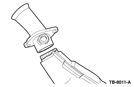
- Slide the revised inlet tube into the catalyst shell. Turn it so the oxygen sensor aligns with the crimp in the catalyst shell (Figure 6).
Figure 6
- Install the catalyst assembly onto the vehicle.
- Use a jack stand to support the rear of the assembly and loosely attach the bolts at the manifold (the correct height of the catalyst at the rear will be set by the new hanger support that is provided in the Kit).
- For vehicles equipped with manual transmissions, remove the damper on the tailshaft housing of the transmission.
- Loosely install the hanger rod and U-clamp around the catalyst pipe near the “Y” of the assembly (Figure 7).
Figure 7
- Slide the rubber isolator and bracket onto the rod with the nuts facing the passenger side of the vehicle.
- Adjust the catalyst height and U-clamp, so the isolator bracket will attach to the transmission extension housing (use rearward holes).
- Install the two (2) bolts that are included in the Kit and tighten to 18 lb-ft (25 N-m).
- Adjust the jack stand, so the hanger rod is in the center of the isolator.
- Tighten U-clamp to 29 lb-ft (40 N-m).
- Remove the jack stand.
- Tighten the catalyst to manifold attaching bolts by alternating each nut to 30 lb-ft (41 N-m).
NOTE: MAKE SURE THAT THE OXYGEN SENSOR ALIGNS WITH THE CRIMPED FLANGE ON TOP OF THE CATALYST BEFORE TACK WELDING (FIGURE 8).
Figure 8
- Tack weld the revised inlet pipe to the catalyst in three (3) places (Figure 9).
Figure 9
- Remove the catalyst assembly from the vehicle (refer to Section 309-00 of the Workshop Manual).
- Remove the oxygen sensor.
- Complete the weld using stainless wire to assure a lasting weld.
- Proceed to the INSTALLATION OF THE AIR CONDITIONER DRIP SHIELD.
INSTALLATION OF THE AIR CONDITIONER DRIP SHIELD
- Loosen the bottom of the right front fender splash shield by removing the three (3) lower pushpin fasteners.
- FOR CONVERTIBLES ONLY: Remove the front attachment for the right side X-brace.
- Locate the air conditioner condensate discharge tube and install the air conditioner drip shield over it, by installing the clip on the shield over the upper frame rail located just below the air conditioner drier bottle (Figure 10).
Figure 10
NOTE: THE SHIELD MUST LIE AS CLOSE TO THE FLOOR PAN AS POSSIBLE.
- Lower the vehicle.
- Push the shield clip down onto the rail.
- Raise the vehicle.
- Attach the lower leg of the shield in an existing bolt hole by installing the bolt provided in the Kit.
- FOR CONVERTIBLES ONLY: Trap the shield between the X-brace and the crossmember. Tighten to 25 lb-ft (34 N-m).
- Reinstall the pushpin fasteners in the fender splash shield.
- Proceed to INSTALLATION OF THE CATALYST SYSTEM.
INSTALLATION OF THE CATALYST SYSTEM
- Install the catalyst system into the vehicle, using the isolator bracket at the transmission.
- Tighten the catalyst to the exhaust manifold fasteners to 30 lb-ft (41 N-m).
- Attach the muffler inlet pipe and tighten to 26 lb-ft (35 N-m).
- Check the system for grounding.
- Lower the vehicle.
- Reconnect the battery.
- Start the engine and check for exhaust leaks.
| PART NUMBER | PART NAME |
| 3R3Z-5H264-MT | Exhaust Kit (Manual Transmission) |
| 3R3Z-5H264-AT | Exhaust Kit (Automatic Transmission) |
SEOCONTENT-START
TSB 04-21-06
SEOCONTENT-END
- Dual 2.5" O.D. Mandrel Bent Aluminized Tail Pipes
- No Welding Required
- Hardware Included
- Can be installed with basic hand tools
- Fit type: Universal Fit
- Dyno-tuned for Maximum Performance
- Full Stainless Steel Construction
- Aggressive Race Proven Outlaw Mufflers
- 【FITMENT】Compatible with 11-14 Ford
 Mustang
 5.0L 5.4L
 - 【Quality Construction】Made of High Quality T-304 Stainless Steel with Computerized Mandrel-Bends for Strength and Durability
- 【Enhance Performence】Dyno proven to instantly increases 15 - 25 horsepower / low end torque. Aggressive deep and smooth tone while ensures smooth exhaust gas flow, increase engine output and efficiency.
- 【Long Term Durability】TIG welded CNC machine flange for resistance against pressure and corrosion.
- 【Design】The larger pipes, low-restriction mufflers, and tuned resonators of a well-designed performance exhaust system can make stunned effect on your vehicle: lower auto exhaust back pressure and a much better sound.
- Vehicle Fitment - The Catback System exhaust kit compatible with 2011-2014 Mustang
 5.0/5.4L
 - Engineering Excellence - Trucks are all about dependability and capability, which is why MagnaFlow engineers every one of our durable, corrosion resistant stainless-steel exhausts to last the lifetime of your vehicle
- Reduce Noise - The larger pipes, low-restriction mufflers, and tuned resonators of a well-designed performance exhaust system can make stunned effect on your vehicle: lower auto exhaust back pressure and a much better sound
- Premium Materials - Made of high quality T-304 stainless steel with computerized mandrel-bends for strength and durability; TIG welded CNC machine flange for resistance against pressure and corrosion
- Easy to Install - Direct bolt-on. No drilling or modifications needed for installation. Gaskets and hardware are Included
- Classic MBRP Sound
- Black Powercoated
- High heat black finish warrantied for one year
- Boosts Horsepower and Torque
- Vehicle Compatibility - Cat-back exhaust compatible with 2005-2010 Ford
 Mustang
 . NOTE: Fits 4.6L 5.4L models.
 - Brilliant Performance - Come with [2] high performance racing design axle-back exhaust, can instantly increases 15-25 horsepower or low end torque, maximize to enhance the high exhaust air flow rate without sacrificing the attractive power sound in the smoothest conditions, increase engine output and efficiency.
- Extraordinary Quality - It is constructed of high quality T-304 stainless steel with computerized mandrel-bends for the strength and durability, and the TIG welded CNC machine can resistant against pressure and corrosion.
- Simple Installation - Direct bolt-on OE fitment and replacement for original part, fast and easy for installation without any drilling or modification. Please note: Gaskets and hardware are Included.
- Product Specification - Muffler Exhaust Tip: 4" OD | Major Piping: 2.5" OD | Inlet / Outlet: 2.5" OD | Muffler Tip Type: Round Diagonal Cut Rolled Lip
- Stainless axle back exhaust system from ROUSH
- Fits 2018-2022 Mustang
 GT 5.0's
 - Aggressive, race-inspired sound, looks & performance
- Improves exhaust flow and reduces back pressure
- Includes mufflers, polished tips, clamps and instructions
- Vehicle Compatibility - Cat-back exhaust compatible with 2018-2020 Ford
 Mustang
 . NOTE: Fits 5.0L models.
 - Brilliant Performance - Come with [2] high performance racing design axle-back exhaust and [4] stainless steel muffler tips, can instantly increases 15-25 horsepower or low end torque, maximize to enhance the high exhaust air flow rate without sacrificing the attractive power sound in the smoothest conditions, increase engine output and efficiency.
- Extraordinary Quality - It is constructed of high quality T-304 stainless steel with computerized mandrel-bends for the strength and durability, and the TIG welded CNC machine can resistant against pressure and corrosion.
- Simple Installation - Direct bolt-on OE fitment and replacement for original part, fast and easy for installation without any drilling or modification. Please note: Gaskets and hardware are Included.
- Product Specification - Muffler Exhaust Tip: 4" OD | Inlet: 2.5" OD | Major Piping: 2.5" OD | Muffler Tip Type: Double Walled Round Diagonal Cut Tip
- BBK is your Number One Aftermarket Performance Exhaust Brand in the USA - American Designed and Built
- BBK Exhaust is Built with CNC Mandrel Bent Tubing for 35% Increased Flow Over Stock to Add 10-15 Horespower and Improve Torque and Performance
- Aircraft Quality Construction, Heavy Gauge 1-5/8" Tubing, 3/8" Laser Cut Flanges, Large Bore Patented Designed Collectors and Custom Precision Hand and Robotic Welds for Long Lasting Quality
- Direct "Perfect" Fit Replacement Exhaust includes All New Gaskets and Hardware and Offers Improved Performance and Sound Over Restrictive Stock Systems
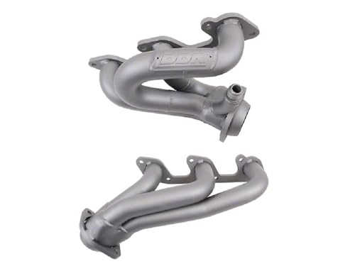
- Bolt on 8-14 HP with these BBK Shorty Tuned Length Exhaust Headers Fit all 2005-2010 Ford
 Mustang
 4.0L V6 Applications - Custom Nickel
Last update on 2025-05-10 / Affiliate links / Images from Amazon Product Advertising API
This product presentation was made with AAWP plugin.


![Exhaust Leak - Cracked or Separated Right Side Exhaust Pipe - 1999-2004 Ford Mustang 13 DNA MOTORING CBE-MU-FM11-50L Stainless Steel Cat Back Exhaust System [Compatible with 11-14 Ford Mustang 5.0L 5.4L ]](https://m.media-amazon.com/images/I/412TI7ecegL.jpg)


When I heard about exhaust leaks in non-modified ford models I thought of the solution I used to fix my leaks. My leaks were at the connector flanges. Heat and vibration is the enemy of an exhaust system. I had reoccurring leaks and inspection failures. Nothing in the aftermarket retail worked to stop reoccurring leaks. I used a C Flange Bracket. No cutting, no welding. Simply install with longer bolts over existing flange or replace damaged flange with this C Flange Bracket and no leak. I passed my inspection. See for yourself on my video links.
https://m.youtube.com/watch?v=zBdFKlVRh48
https://m.youtube.com/watch?v=c1JYhsl0Pq4
https://m.youtube.com/watch?v=t0eHvcnLqAo