May 29, 2014 NHTSA CAMPAIGN NUMBER: 14V284000
Loss of Electric Power Steering Assist
If power steering assist is lost, greater driver effort would be required to steer the vehicle at low speeds, increasing the risk of a crash.
NHTSA Campaign Number: 14V284
Manufacturer Ford![]() Motor Company
Motor Company
Components STEERING
Potential Number of Units Affected 740,878
Summary
Ford![]() Motor Company (Ford
Motor Company (Ford![]() ) is recalling certain model year 2008-2011 Ford
) is recalling certain model year 2008-2011 Ford![]() Escape and Mercury
Escape and Mercury![]() Mariner vehicles manufactured August 18, 2006, through September 11, 2010. The affected vehicles have a steering torque sensor that may not be able to properly detect driver steering input. As a result, the system could remove the Electric Power Steering (EPS) assist.
Mariner vehicles manufactured August 18, 2006, through September 11, 2010. The affected vehicles have a steering torque sensor that may not be able to properly detect driver steering input. As a result, the system could remove the Electric Power Steering (EPS) assist.
Remedy
Ford![]() will notify owners, and dealers will update the software for the power steering control module (PSCM) and the instrument cluster module, free of charge. If a vehicle shows a history of a loss of the torque sensor signal or fault codes relating to the PSCM when the vehicle is brought in for the recall remedy, the affected components will be replaced, free of charge. The recall began on July 18, 2014. Owners may contact Ford
will notify owners, and dealers will update the software for the power steering control module (PSCM) and the instrument cluster module, free of charge. If a vehicle shows a history of a loss of the torque sensor signal or fault codes relating to the PSCM when the vehicle is brought in for the recall remedy, the affected components will be replaced, free of charge. The recall began on July 18, 2014. Owners may contact Ford![]() customer service at 1-800-392-3673. Ford
customer service at 1-800-392-3673. Ford![]() ’s number for this recall is 14S05.
’s number for this recall is 14S05.
Notes
Owners may also contact the National Highway Traffic Safety Administration Vehicle Safety Hotline at 1-888-327-4236 (TTY 1-800-424-9153), or go to www.safercar.gov.
Check if your Vehicle has a Recall
AFFECTED VEHICLES
Certain 2008-2011 model year Escape and Mariner vehicles built at the Kansas City Assembly Plant from Job #1 2008 through September 11, 2010. Affected vehicles are identified in OASIS. In addition, for a list of vehicles assigned to your dealership, visit https://web.fsavinlists.dealerconnection.com. This information was available on May 29, 2014.
REASON FOR THIS SAFETY RECALL
In some of the affected vehicles, the power steering system may revert to manual steering mode due to an Electric Power Steering system fault related to the torque sensor. In manual steering mode there is still a mechanical linkage between the steering wheel and the road wheel, allowing steering control to be maintained. If this condition should occur, the steering effort may be greater at low speeds, which may increase the risk of accident.
SERVICE ACTION
Dealers are to check the Power Steering Control Module (PSCM) for Diagnostic Trouble Codes (DTCs).
- If DTC B1342, B2277, or B2278 are NOT present, reprogram the PSCM and the Instrument Cluster (IC) module.
- If only DTC B2278 is present, replace the torque sensor.
- If DTC B1342 or B2277 is present, replace the steering column assembly.
NOTE: The software to perform the repair is currently not available to support Safety Recall 14S05, but will be released on July 9, 2014. Until IDS release 91.02 is available, customer vehicles should be repaired only if the vehicle arrives at your dealership with a customer complaint of loss of steering assist accompanied by one of the DTCs noted above.
One of the above services must be performed on all affected vehicles at no charge to the vehicle owner.
Dealership service management must provide a copy of the Customer Information Sheet (posted with this bulletin) to the owners of all vehicles that had modules reprogrammed (did not receive a replacement torque sensor or steering column). This Customer Information Sheet provides information on the warnings that may now display on the instrument cluster message center.
OWNER NOTIFICATION MAILING SCHEDULE
Owner Letters are expected to be mailed the week of July 14, 2014. Dealers should repair any affected vehicles that arrive at their dealerships, whether or not the customer has received a letter.
STOCK VEHICLES
Use OASIS to identify any affected vehicles in your used vehicle inventory.
SOLD VEHICLES
- Owners of affected vehicles will be directed to dealers for repairs.
- Immediately contact any of your affected customers whose vehicles are not on your VIN list but are identified in Give the customer a copy of the Owner Notification Letter (when available) and schedule a service date.
- Correct other affected vehicles identified in OASIS which are brought to your dealership.
TITLE BRANDED / SALVAGED VEHICLES
Affected title branded and salvaged vehicles are eligible for this recall.
RELATED DAMAGE
If a related damage condition exists that you believe to be caused by the covered condition, call the Special Service Support Center to request approval prior to the repair of any related damage.
Requests for approval after completion of the repair will not be granted. Ford![]() Motor Company reserves the right to deny coverage for related damage in cases where the vehicle owner has not had this recall performed on a timely basis. Additional related damage parts are subject to random selection for return to the Ford
Motor Company reserves the right to deny coverage for related damage in cases where the vehicle owner has not had this recall performed on a timely basis. Additional related damage parts are subject to random selection for return to the Ford![]() Warranty Parts Analysis Center (WPAC).
Warranty Parts Analysis Center (WPAC).
OWNER REFUNDS
- This safety recall must still be performed, even if the owner has paid for a previous Claiming a refund will not close the recall on the vehicle.
- Ford
 Motor Company is offering a refund for owner-paid repairs covered by this recall if the repair was performed prior to the date indicated in the reimbursement plan, which is posted with this Owners are directed to seek reimbursement through authorized dealers or, at their option, directly through Ford Motor Company at P.O. Box 6251, Dearborn, MI 48121- 6251.
 - Dealers are also authorized to refund owner-paid emergency repairs that were performed away from an authorized servicing dealer after the end date specified in the reimbursement Non-covered repairs, or those judged by Ford to be excessive, will not be reimbursed.
- Refunds will only be provided for the cost associated with steering column or torque sensor replacement for loss of steering assist.
RENTAL VEHICLES
If a customer’s vehicle requires the replacement of the steering column or torque sensor and it is necessary to order parts, Ford![]() Motor Company will pay for one day of vehicle rental. Follow Extended Service Plan (ESP) guidelines for dollar amounts. The daily rate can include applicable taxes but is not allowed to exceed the stated daily rate. Rentals will only be reimbursed for the day the vehicle is at the dealership for part replacement. Prior approval for more than one rental day is required from the Special Service Support Center (1-800-325-5621). The parts order must be an emergency order (unit down) to guarantee the shortest delivery time.
Motor Company will pay for one day of vehicle rental. Follow Extended Service Plan (ESP) guidelines for dollar amounts. The daily rate can include applicable taxes but is not allowed to exceed the stated daily rate. Rentals will only be reimbursed for the day the vehicle is at the dealership for part replacement. Prior approval for more than one rental day is required from the Special Service Support Center (1-800-325-5621). The parts order must be an emergency order (unit down) to guarantee the shortest delivery time.
PARTS REQUIREMENTS
Torque Sensor
| Part Number | Description | Quantity |
|---|---|---|
| CL8Z-3F818-A No products found. | Torque Sensor | 1 |
| W712250–S437 | Upper Column Bolt | 2 |
Steering Column Assembly
| Part Number | Description | Quantity |
|---|---|---|
| CL8Z-3C529-C | Steering Column Assembly | 1 |
| W713065-S439 | Steering Column Coupling-to-Steering Gear Bolt | 1 |
| W712250–S437 | Upper Column Bolt | 2 |

Safety Recall 14S05
Certain 2008-2011 Model Year Escape and Mariner Vehicles
Electric Power Steering
DEALER Q & A
Q1. What is the problem?
Ford![]() is voluntarily recalling certain 2008-2011 model year Escape and Mariner vehicles to address concerns relating to power steering operation. In some of the affected vehicles, the power steering system may revert to manual steering mode due to an Electric Power Steering system fault related to the torque sensor. In manual steering mode there is still a mechanical linkage between the steering wheel and the road wheel, allowing steering control to be maintained. If this condition should occur, the steering effort may be greater at low speeds, which may increase the risk of accident.
is voluntarily recalling certain 2008-2011 model year Escape and Mariner vehicles to address concerns relating to power steering operation. In some of the affected vehicles, the power steering system may revert to manual steering mode due to an Electric Power Steering system fault related to the torque sensor. In manual steering mode there is still a mechanical linkage between the steering wheel and the road wheel, allowing steering control to be maintained. If this condition should occur, the steering effort may be greater at low speeds, which may increase the risk of accident.
Q2. Why are some vehicles repaired through part replacement and others repaired through module reprograming?
Each of these repairs mitigates the safety risk associated with this recall. The replacement torque sensor and steering column have improved durability to prevent the condition that results in loss of steering assist. Reprograming the modules will prevent the sudden loss of steering assist while driving, will display a warning light or message, and a chime will sound to inform the driver.
Q3. What does the software updates do?
The software updates may extend the time steering assist is maintained. In addition, the update provides increased driver awareness by sounding a chime and displaying the wrench light or warning in the message center when a fault is detected.
Q4. What if a customer experiences loss of steering assist after the modules have been reprogrammed?
The modules were reprogrammed to prevent sudden loss of steering assist while driving. Additionally, the instrument cluster software update will provide audible and visual indications to the driver in the unlikely event of a torque sensor fault. Any subsequent loss of assist repairs experienced after completion of module reprogramming are not covered by this recall.
Q5. What should I tell a customer who experiences loss of steering assist after the recall has been performed?
The modules were reprogrammed to prevent sudden loss of steering assist while driving in the event of a torque sensor fault. Customers should be advised that the replacement of the steering column or torque sensor is at their expense.
CERTAIN 2008-2011 MODEL YEAR ESCAPE AND MARINER VEHICLES — ELECTRIC POWER STEERING
OVERVIEW
In some of the affected vehicles, the power steering system may revert to manual steering mode due to an Electric Power Steering (EPS) system fault related to the torque sensor. In manual steering mode there is still a mechanical linkage between the steering wheel and the road wheel, allowing steering control to be maintained. If this condition should occur, the steering effort may be greater at low speeds, which may increase the risk of accident.
SERVICE PROCEDURE
- Connect IDS and check for Diagnostic Trouble Codes (DTCs) in the Power Steering Control Module (PSCM).
- If DTC B1342, B2277, or B2278 are NOT present, reprogram the PSCM and the Instrument Cluster (IC) Proceed to “Module Reprogramming” on Page 2.
- If only DTC B2278 is present, replace the torque Proceed to “Torque Sensor Replacement” on Page 4.
- If DTC codes B1342 or B2277 are present, replace the steering column. For additional information, refer to Workshop Manual (WSM) Section 211-04.
NOTE: None of the modules need to be reprogrammed if the torque sensor or the steering column is replaced.
Important Information for Module Programming
NOTE: When programming or reprogramming a module, use the following basic checks to ensure programming completes without errors.
- Make sure the 12V battery is fully charged before carrying out the programming steps and connect IDS/scan tool to a power source.
- Inspect Vehicle Communication Module (VCM) and cables for any Make sure scan tool connections are not interrupted during programming.
- A hardwired internet connection is strongly recommended.
- Turn off all unnecessary accessories (radio, heated/cooled seats, head lamps, interior lamps, HVAC system, etc.) and close doors.
- Disconnect/depower any aftermarket accessories (remote start, alarm, power inverter, CB radio, ).
- Follow all scan tool on-screen instructions carefully.
- Disable IDS/scan tool sleep mode, screensaver, hibernation modes.
- Create all sessions Key On Engine Off (KOEO). Starting the vehicle before creating a session will cause errors within the programming inhale process.
Module Reprogramming
NOTE: Reprogram appropriate vehicle modules before performing diagnostics and clear all Diagnostic Trouble Codes (DTCs) after programming. For DTCs generated after reprogramming, follow normal diagnostic service procedures.
- Reprogram the PSCM and IC module using IDS release 91.02 or higher.
NOTE: All PSCMs require an update, but only some IC modules require an update.
NOTE: Calibration files may also be obtained at www.motorcraft.com.
NOTE: Follow the IDS on-screen instructions to complete the reprogramming procedure.
Recovering a module when programming has resulted in a blank module:
NEVER DELETE THE ORIGINAL SESSION!
- a. Obtain the original IDS that was used when the programming error occurred during Module Reprogramming (MR) or Programmable Module Installation (PMI).
- b. Disconnect the VCM from the data link connector (DLC) and the IDS.
- c. Reconnect the VCM to IDS and then connect to the Once reconnected, the VCM icon should appear in the corner of the IDS screen. If it does not, troubleshoot the IDS to VCM connection.
- d. Locate the ORIGINAL vehicle session when programming This should be the last session used in most cases. If not, use the session created on the date that the programming failed.
NOTE: If the original session is not listed in the previous session list, click the ”Recycle Bin” icon at the lower right of the previous session screen. This loads any deleted sessions and allows you to look through them. Double-click the session to restore it.
- e. Once the session is loaded, the failed process should resume automatically.
- f. If programming does not resume automatically, proceed to the Module Programming menu and select the previously attempted process, PMI or MR.
- g. Follow all on-screen prompts/instructions.
- h. Near the end of programming, the IDS prompts you to select certain It is important to make a selection for ALL parameters listed. If the correct selection is already highlighted, you must still choose that selection before clicking the “Tick” mark to complete the configuration.
- i. The last screen on the IDS may list additional steps required to complete the programming process. Make sure all applicable steps listed on the screen are followed in order.
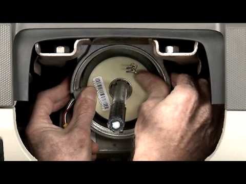
Torque Sensor Replacement
NOTE: This procedure must take place in a clean environment to ensure no contamination enters the worm gear.
NOTE: For clarity, some illustrations show an orientation different from the actual work perspective.
- With the vehicle in NEUTRAL, position it on a hoist. For additional information, refer to WSM Section 100-02.
- For ease of assembly, turn the steering wheel to the 11:00 o’clock position.
- Hybrid vehicles: Depower the high-voltage traction For additional information, refer to WSM Section 414-03.
- Disconnect the 12V For additional information, refer to WSM Section 414-01.
- Remove the steering column opening trim. See Figure 1.

Figure 1
- If present, use a suitable cutting tool to carefully cut through the two cutoff lines and discard the instrument panel cutout. See Figure 2.
NOTE: Steering column removed for clarity.

Figure 2
NOTE: Steering column removed for clarity.

Figure 3
- Pull up and remove the upper column shroud. See Figure 4.

Figure 4
Remove the three machine screws and the lower column shroud. See Figure 5.

Figure 5
- Disconnect the three connectors on the left side of the column. Remove the two harness pin-type See Figure 6.

Figure 6
- If equipped, disconnect the Passive Anti-Theft System (PATS) transceiver electrical Remove the harness pin-type retainer and position the harness aside. See Figure 7.

Figure 7
- Remove and discard the two upper column See Figure 8.

Figure 8
- Tape the wheel to the Multifunction Switch (MFS) to prevent rotation of the wheel. Pull out and remove the steering wheel and upper column assembly as a single unit. See Figure 9.

Figure 9
- Remove the snap ring using Rotor Clip RP-900 ratchet and grip ring pliers or Remove the lower jacket. See Figure 10.

Figure 10

Figure 11
- Disconnect the torque sensor electrical connector and remove the harness pin-type See Figure 12.

Figure 12
- Raise the front of the vehicle high enough to remove the load off the front For additional information, refer to WSM Section 100-02.
To see a short video of the torque sensor installation, click “Here“.
IMPORTANT: Do not use pliers or locking pliers to turn the steering shaft or damage will occur. Two people are required to properly align the torque sensor.
- Before removing the old torque sensor assembly, verify the steering shaft keyway is aligned with the sensor alignment mark. This will ensure that the steering input shaft is in the correct position for installation of the sensor alignment tool. (If necessary, have an assistant bump the front tires left or right until the sensor is perfectly aligned.) See Figure 13.

Figure 13
- Prying gently from the back, remove the torque sensor assembly. Remove the sensor by gently pulling up on the sensor wires while using a hooked pick tool to lift the opposite side of the sensor. See Figure 14.

Figure 14
- Inspect the underside of the sensor for In case of breakage or damage, replace the steering column. For additional information, refer to WSM Section 211-04.
- Vacuum the surface of the gear face to remove any Thoroughly vacuum the worm gear. See Figure 15.

Figure 15
IMPORTANT: Up and down movement of the steering gear assembly in the vehicle will cause the steering shaft to rotate slightly. When you begin the next step, you MUST keep the steering gear assembly “locked” in the same position. Up and down movement of the steering gear during alignment and installation process will result in a misaligned torque sensor.
IMPORTANT: The following steps (22 through 28) are CRITICAL for the proper installation of the torque sensor assembly.
NOTICE: The new torque sensor will come with a locking pin that ensures the steering angle sensor and the steering torque sensor are “locked” in the proper position. DO NOT remove this pin until the sensor assembly is completely installed.
NOTE: Do not force tool into place, the tool must feel loose when in proper position.
- Install the alignment tool. During installation of the tool, the tool key on the alignment tool should slide easily into the steering shaft key way. If there is any binding, have an assistant bump the tires slightly to the right or left again until the alignment tool falls into place. See Figure 16.

Figure 16
- While the alignment tool is in place, attempt to rotate the tool in the clockwise and counter-clockwise direction.
- If the alignment tool can freely rotate slightly in the clockwise and counter-clockwise direction, the tool is properly aligned. Proceed to Step 24. See Figure 17.
- If the alignment tool cannot freely rotate, the steering shaft is not Have an assistant bump the tires slightly until the alignment tool can be rotated slightly.
NOTE: The alignment tool should not feel stiff while rotating. If it does, the steering shaft is not aligned.

Figure 17
- After the steering shaft is perfectly aligned with the spline on the alignment tool, remove the alignment tool and carefully install the torque sensor assembly with the locking pin still in When seating the torque sensor assembly, apply gentle but even force on both sides of the sensor (DO NOT REMOVE THE LOCKING PIN YET). See Figure 18.

Figure 18
- Ensure the locking pin is not shifted to one side of the sensor viewing The optimal position for the locking pin is centered in the viewing window. See Figure 19.

Figure 19
- Fully Seating the Torque Sensor Assembly:
NOTICE: DO NOT push the torque sensor assembly past flush with the gear housing rim or damage to the sensor will occur.
Use the alignment tool to verify the torque sensor assembly is seated properly. The top of the alignment tool should be flush with gear housing rim. See Figure 20.

Figure 20
NOTICE: Do not drop the locking pin into the steering gear housing or damage may occur.
- While the alignment tool is still in place, remove the locking pin, then remove the alignment tool. See Figure 21.

Figure 21
TIP: When the locking pin is removed, the locking pin hole should still be visible inside the sensor viewing window. If the sensor was not properly aligned during installation, the locking pin hole will move out of view when the locking pin is removed.
- Check locking pin hole location.
- If the locking pin hole is completely visible (Figure 22a), the sensor is installed Proceed to Step 29.
- If the locking pin is not completely visible (Figure 22b), remove and discard the torque Obtain a new torque sensor and repeat Steps 22 through 28. See Figure 22a and 22b.

Figure 22a Figure 22b
- Connect the torque sensor electrical connector and install the harness pin-type See Figure 12.
- Reinstall the sensor seal onto the steering assist See Figure 11.
- Install the lower jacket and the original snap ring bevel side See Figure 23.

Figure 23
- Ensure snap ring gap is positioned 90 degrees from sensor seal. Measure the gap between snap ring Gap must be 18 – 20mm (3/4 in) to ensure snap ring is seated correctly. See Figure 24.

Figure 24
NOTE: The steering wheel and upper steering column assembly should slide on easily. Significant resistance means the upper column assembly is not properly aligned. If necessary, rotate the upper column assembly for proper alignment. All rotating parts must be properly aligned during assembly. Position tolerance ± 5 degrees.
- Install the steering wheel and upper column assembly and remove the Rotate the upper column assembly as necessary to align with block tooth on shaft.
- Install two (2) new upper column See Figure 8.
- Tighten bolts to 28 Nm (21 lb-ft).
- If equipped, connect the PATS transceiver electrical Reposition the harness and install the pin-type retainer. See Figure 7.
- Connect the three connectors on the left side of the column. Install the two harness pin-type See Figure 6.
- Install the lower column shroud and tighten the three machine See Figure 5.
- Install the upper column shroud. See Figure 4.
- Install the four bolts and the steering column opening panel. See Figure 3.
- Tighten to 8 Nm (71 lb-in).
- Install the steering column opening trim. See Figure 1.
- Connect the 12V For additional information, refer to WSM Section 414-01.
- Hybrid vehicles: Repower the high-voltage traction For additional information, refer to WSM Section 414-03.
- Lower the vehicle and start the With the engine running and a properly installed sensor, the steering wheel should stay centered. If the torque sensor is NOT installed properly (i.e. not centered during installation), the steering wheel will move all the way to the right or left. The torque sensor only needs to be off center a small amount to cause this type of problem. During normal operation, the torque sensor only moves a maximum -5 degree to +5 degrees.
- Perform Steering Wheel Position Sensor For additional information, refer to WSM Section 211-00.
SEOCONTENT-START**************************************************************************************************************Ford![]() Motor Company Ford
Motor Company Ford![]() Customer Service Division P.O. Box 1904 Dearborn, Michigan 48121 August 2015 2010 Mariner Vehicle ID#: * * * IMPORT ANT SAFETY RECALL REMINDER * * * (RECORDATOR/0 IMPORTANTE PROGRAMA DE SEGUR/DAD) According to our records, your 2010 Mariner has not had necessary safety recall repairs made. We urge you to have the free repair performed at your local dealership as soon as possible. KEY INFORMATION • Your vehicle is involved in an important safety recall • Your safety is important to us. Schedule an appointment to have service procedure completed • This procedure will be performed free of charge • Si necesita ayuda o tiene alguna pregunta, por favor flame al Centro de Relaci6n con Clientes al 1-866-436-7332 y presione 2 para Espanol Recall Number 14S05 – Electric Power Steering and Description: What is the Issue? What Are We Asking You To Do? Service Assistance: On your vehicle, the power steering system may revert to manual steering mode due to an Electric Power Steering system fault related to the torque sensor. An unexpected loss of steering assist while driving would require higher steering effort at lower vehicle speeds, which may increase the risk of accident. Please contact your dealer to schedule an appointment to have this important service procedure completed. If you do not already have a servicing dealer, you can access www.Fordowner.com for dealer addresses, maps and driving instructions. The vehicle owner is responsible for having this service action performed. Ford
Customer Service Division P.O. Box 1904 Dearborn, Michigan 48121 August 2015 2010 Mariner Vehicle ID#: * * * IMPORT ANT SAFETY RECALL REMINDER * * * (RECORDATOR/0 IMPORTANTE PROGRAMA DE SEGUR/DAD) According to our records, your 2010 Mariner has not had necessary safety recall repairs made. We urge you to have the free repair performed at your local dealership as soon as possible. KEY INFORMATION • Your vehicle is involved in an important safety recall • Your safety is important to us. Schedule an appointment to have service procedure completed • This procedure will be performed free of charge • Si necesita ayuda o tiene alguna pregunta, por favor flame al Centro de Relaci6n con Clientes al 1-866-436-7332 y presione 2 para Espanol Recall Number 14S05 – Electric Power Steering and Description: What is the Issue? What Are We Asking You To Do? Service Assistance: On your vehicle, the power steering system may revert to manual steering mode due to an Electric Power Steering system fault related to the torque sensor. An unexpected loss of steering assist while driving would require higher steering effort at lower vehicle speeds, which may increase the risk of accident. Please contact your dealer to schedule an appointment to have this important service procedure completed. If you do not already have a servicing dealer, you can access www.Fordowner.com for dealer addresses, maps and driving instructions. The vehicle owner is responsible for having this service action performed. Ford![]() Motor Company reserves the right to deny coverage for any vehicle damage that may result from failure to have this recall performed on a timely basis. Therefore, please have this recall performed as soon as possible. If you have additional questions, please contact the Ford
Motor Company reserves the right to deny coverage for any vehicle damage that may result from failure to have this recall performed on a timely basis. Therefore, please have this recall performed as soon as possible. If you have additional questions, please contact the Ford![]() Motor Company Customer Relationship Center at 1-866-436-7332 and one of our representatives will be happy to assist you. For the hearing impaired call 1-800-232-5952 (TDD). Office Hours are Monday through Friday: 8:00AM – 5:00PM (Your Local Time). If you wish to contact us through the Internet, our address is: www.Fordowner.com. If your authorized dealer has recently completed this recall repair, please disregard this reminder. We apologize for any inconvenience this may cause and want to assure you that, with your assistance, we will correct this condition. Our commitment, together with your dealer, is to provide you with the highest level of service and support. Thank you for your attention to this important matter. Ford
Motor Company Customer Relationship Center at 1-866-436-7332 and one of our representatives will be happy to assist you. For the hearing impaired call 1-800-232-5952 (TDD). Office Hours are Monday through Friday: 8:00AM – 5:00PM (Your Local Time). If you wish to contact us through the Internet, our address is: www.Fordowner.com. If your authorized dealer has recently completed this recall repair, please disregard this reminder. We apologize for any inconvenience this may cause and want to assure you that, with your assistance, we will correct this condition. Our commitment, together with your dealer, is to provide you with the highest level of service and support. Thank you for your attention to this important matter. Ford![]() Customer Service Division **************************************************************************************************************
Customer Service Division **************************************************************************************************************
Ford![]() Motor Company Ford
Motor Company Ford![]() Customer Service Division P.O. Box 1904 Dearborn, Michigan 48121-1904 August 2017 * * * IMPORTANT SAFETY RECALL REMINDER** * (RECORDATOR/0 IMPORTANTE PROGRAMA DE SEGUR/DAD) According to our records, your 2011 Escape has not had necessary safety recall repairs made. We urge you to have the free repair performed at your local dealership as soon as possible. KEY INFORMATION • Your vehicle is involved in an important safety recall • Your safety is important to us. Schedule an appointment to have service procedure completed • This procedure will be performed free of charge • Si necesita ayuda o tiene alguna pregunta, por favor /lame al Centro de Relaci6n con Clientes al 1-866-436-7332 y presione 2 para Espanol Recall Number 14S05 – Electric Power Steering and Description: What is the Issue? What Are We Asking You To Do? Service Assistance: On your vehicle, the power steering system may revert to manual steering mode due to an Electric Power Steering system fault related to the torque sensor An unexpected loss of steering assist while driving would require higher steering effort at lower vehicle speeds, which may increase the risk of accident. Please contact your dealer to schedule an appointment to have this important service procedure completed. If you do not already have a servicing dealer, you can access www.Fordowner.com for dealer addresses, maps and driving instructions. The vehicle owner is responsible for having this service action performed. Ford Motor Company reserves the right to deny coverage for any vehicle damage that may result from failure to have this recall performed on a timely basis. Therefore, please have this recall performed as soon as possible. If you have additional questions, please contact the Ford Motor Company Customer Relationship Center at 1-866-436-7332 and one of our representatives will be happy to assist you. For the hearing impaired call 1-800-232-5952 (TDD). Office Hours are Monday through Friday: 8:00AM – 5:00PM (Your Local Time). If you wish to contact us through the Internet, our address is: www.Fordowner.com. ff your authorized dealer has recently completed this recall repair, please disregard this reminder. We apologize for any inconvenience this may cause and want to assure you that, with your assistance, we will correct this condition. Our commitment, together with your dealer, is to provi,de you with th’e highest level of service and support. Thank you for your attention to this important matter. Ford Customer Service Division **************************************************************************************************************
Customer Service Division P.O. Box 1904 Dearborn, Michigan 48121-1904 August 2017 * * * IMPORTANT SAFETY RECALL REMINDER** * (RECORDATOR/0 IMPORTANTE PROGRAMA DE SEGUR/DAD) According to our records, your 2011 Escape has not had necessary safety recall repairs made. We urge you to have the free repair performed at your local dealership as soon as possible. KEY INFORMATION • Your vehicle is involved in an important safety recall • Your safety is important to us. Schedule an appointment to have service procedure completed • This procedure will be performed free of charge • Si necesita ayuda o tiene alguna pregunta, por favor /lame al Centro de Relaci6n con Clientes al 1-866-436-7332 y presione 2 para Espanol Recall Number 14S05 – Electric Power Steering and Description: What is the Issue? What Are We Asking You To Do? Service Assistance: On your vehicle, the power steering system may revert to manual steering mode due to an Electric Power Steering system fault related to the torque sensor An unexpected loss of steering assist while driving would require higher steering effort at lower vehicle speeds, which may increase the risk of accident. Please contact your dealer to schedule an appointment to have this important service procedure completed. If you do not already have a servicing dealer, you can access www.Fordowner.com for dealer addresses, maps and driving instructions. The vehicle owner is responsible for having this service action performed. Ford Motor Company reserves the right to deny coverage for any vehicle damage that may result from failure to have this recall performed on a timely basis. Therefore, please have this recall performed as soon as possible. If you have additional questions, please contact the Ford Motor Company Customer Relationship Center at 1-866-436-7332 and one of our representatives will be happy to assist you. For the hearing impaired call 1-800-232-5952 (TDD). Office Hours are Monday through Friday: 8:00AM – 5:00PM (Your Local Time). If you wish to contact us through the Internet, our address is: www.Fordowner.com. ff your authorized dealer has recently completed this recall repair, please disregard this reminder. We apologize for any inconvenience this may cause and want to assure you that, with your assistance, we will correct this condition. Our commitment, together with your dealer, is to provi,de you with th’e highest level of service and support. Thank you for your attention to this important matter. Ford Customer Service Division **************************************************************************************************************
Ford Motor Company Ford Customer Service Division p, 0, Box 1904 Dearborn, Michigan 48121 R. FILE 330 TOWN CENTER DR STE 500 DEARBORN, MI 48126-2796 July 2014 * * * IMPORTANT SAFETY RECALL * * * (PROGRAMA DE SEGUR/DAD /MPORTANTE) Safety Recall Notice 14505 J NHT5A RecaU14V-284 Aviso de Revision de 5eguridad 14505 This notice applies to your vehicle: 2011 Escape Your Vehicle Identification Number: This notice is sent to you in accordance with the requirements of the National Traffic and Motor Vehicle Safety Act. Ford Motor Company has decided that a defect which relates to motor vehicle safety exists in your vehicle, with the Vehicle Identification Number shown above, We apologize for this situation and want to assure you that, with your assistance, we will correct this condition. Our commitment, together with your dealer, is to provide you with the highest level of service and support. What is the issue? What will Ford and your dealer do? How long will it take? What should you do? On your vehicle, the power steering system may revert to manual steering mode dlJ’3 to an Electric Power Steering system fault re!ated to the torque sensor. An unexpected loss of steering assist while driving would require higher steering effort at lower vehicle speeds, which may increase the risk of accident. Ford Motor Company has authorized your dealer to update the appropriate modules to prevent loss of steering assist while driving due to a torque sensor fault. In addition, the update provides increased driver awareness by sounding a chime and displaying the wrench light or warning in the message center when a fault is detected, Alternatively, the dealer may need to replace the torque sensor or the steering column. This service will be performed free of charge (parts and labor). The time needed for this repair is less than one-half day, However, due to service scheduling requirements, your dealer may need your vehicle for a longer period of time. Please call your dealer without delay and request a service date for Recall 14S05. Provide the dealer with the Vehicle Identification Number (VIN) of your vehicle. The VIN is printed near your name at the beginning of this letter. If you do not already have a servicing dealer, you can access www.Fordowner.com for dealer addresses, maps, and driving instructions. What should you do? (Continued) Have you previously paid for this repair? What if you no longer own this vehicle? Ford Motor Company wants you to have this safety recall completed on your vehicle. The vehicle owner is responsible for making arrangements to have the work completed. Please note: Federal law requires that any vehicle lessor receiving this recall notice must forward a copy of this notice to the lessee within ten days. If you have previously paid for a repair that addresses the issue described in this letter, you still need to have this recall performed to ensure the correct parts and procedures were used. You may be eligible for a refund of previously paid repairs. Refunds will only be provided for service related to steering column or torque sensor replacement for loss of power steering assist. To verify eligibility and expedite reimbursement, give your paid original receipt to your dealer. Refund requests may also be sent directly to Ford Motor Company. To request your refund from Ford, send the refund request with all required documentation, including your original repair receipt (no photocopies), to Ford Motor Company at P.O. Box 6251, Dearborn, Michigail4812~-625~. Refund requests mailed tc th:s address may take up to 60 days to process. Your original receipt will be returned to you. Detailed information regarding eligibility for Ford’s reimbursement program and documentation requirements may be obtained by contacting the Ford Customer Relationship Center at 1-866-436-7332. If you no longer own this vehicle, and have an address for the current owner, please forward this letter to the new owner. You received this notice because government regulations require that notification be sent to the last known owner of record. Our records are based primarily on state registration and title data, which indicate that you are the current owner. If you have difficulties getting your vehicle repaired promptly and without charge, please contact your dealership’s Service Manager for assistance. RETAIL OWNERS: If you still have concerns, please contact the Ford Motor Company Customer Relationship Center at 1-866-436-7332 and one of our representatives will be happy to assist you. For the hearing impaired call 1-800-232-5952 (TOO). Representatives are available Monday through Friday: 8:00AM – 8:00PM (Eastern Time). If you wish to contact us through the Internet, our address is: www.Fordowner.com. Para esistencie en Espano/:’ Si necesita ayuda 0 tiene a/guna pregunta, por favor /lame a/ Centro de Re/aci6n con C/ientes a/1-866-436-7332 y presione 2 para Espano/. FLEET OWNERS: If you still have concerns, please contact the Fleet Customer Information Center at 1-800-34-FLEET, Option #3 and one of our representatives will be happy to assist you. Representatives are available Monday through Friday: 8:00AM – 8:00PM (Eastern Time). Or you may contact us through the Internet at www.fleetJord.com. If you are still having difficulty getting your vehicle repaired in a reasonable time or without charge, you may write the Administrator, National Highway Traffic Safety Administration, 1200 New Jersey Ave. S.E., Washington, D.C. 20590 or call the toll free Vehicle Safety Hotline at 1-888-327-4236 (TTY: 1-800-424-9153) or go to www.safercar.gov. Reference NHTSA Safety Recall 14V-284. Thank you for your attention to this important matter. Can we assist you further? 2012 24774/123623/0586 Ford Customer Service Division **************************************************************************************************************
Michael A. Berardi Director Service Engineering Operations Ford Customer Service Division Ford Motor Company P. O. Box 1904 Dearborn, Michigan 48121 May 29,2014 TO: All U.S. Ford and Lincoln![]() Dealers SUBJECT: Advance Notice – Safety Recall 14S05 Certain 2008-2011 Model Year Escape and Mariner Vehicles Electric Power Steering AFFECTED VEHICLES Certain 2008-2011 model year Escape and Mariner vehicles built at the Kansas City Assembly Plant from Job #1 2008 through September 11, 2010. Affected vehicles are identified in OASIS. In addition, for a list of vehicles assigned to your dealership, visit https://web.fsavinlists.dealerconnection.com. This information will be available on May 29, 2014. REASON FOR THIS SAFETY RECALL In some of the affected vehicles, the power steering system may revert to manual steering mode due to an Electric Power Steering system fault related to the torque sensor. In manual steering mode there is still a mechanical linkage between the steering wheel and the road wheel, allowing steering control to be maintained. If this condition should occur, the steering effort may be greater, especially at low speeds, which may increase the risk of accident. SERVICE ACTION It is anticipated that a complete Dealer Bulletin will be provided to dealers by the week of June 16, 2014, once the software to perform the repair is available. NOTE: The software to perform the repair is currently not available to support Safety Recall 14S05, but is expected to be released in mid-June. In the interim period, if an affected vehicle arrives at your dealership with a customer complaint of loss of steering assist, please contact the Special Service Support Center for direction. CUSTOMER NOTIFICATION Owners of record will be notified via first-class mail after repair instructions and parts ordering information have been provided to dealers. QUESTIONS? Special Service Support Center (Dealer Assistance Only) 1-800-325-5621 Sincerely, Michael A Berardi **************************************************************************************************************
Dealers SUBJECT: Advance Notice – Safety Recall 14S05 Certain 2008-2011 Model Year Escape and Mariner Vehicles Electric Power Steering AFFECTED VEHICLES Certain 2008-2011 model year Escape and Mariner vehicles built at the Kansas City Assembly Plant from Job #1 2008 through September 11, 2010. Affected vehicles are identified in OASIS. In addition, for a list of vehicles assigned to your dealership, visit https://web.fsavinlists.dealerconnection.com. This information will be available on May 29, 2014. REASON FOR THIS SAFETY RECALL In some of the affected vehicles, the power steering system may revert to manual steering mode due to an Electric Power Steering system fault related to the torque sensor. In manual steering mode there is still a mechanical linkage between the steering wheel and the road wheel, allowing steering control to be maintained. If this condition should occur, the steering effort may be greater, especially at low speeds, which may increase the risk of accident. SERVICE ACTION It is anticipated that a complete Dealer Bulletin will be provided to dealers by the week of June 16, 2014, once the software to perform the repair is available. NOTE: The software to perform the repair is currently not available to support Safety Recall 14S05, but is expected to be released in mid-June. In the interim period, if an affected vehicle arrives at your dealership with a customer complaint of loss of steering assist, please contact the Special Service Support Center for direction. CUSTOMER NOTIFICATION Owners of record will be notified via first-class mail after repair instructions and parts ordering information have been provided to dealers. QUESTIONS? Special Service Support Center (Dealer Assistance Only) 1-800-325-5621 Sincerely, Michael A Berardi **************************************************************************************************************
Michael A. Berardi Ford Motor Company Director P. O. Box 1904 Service Engineering Operations Dearborn, Michigan 48121 Ford Customer Service Division July 1, 2014 TO: All U.S. Ford and Lincoln![]() Dealers SUBJECT: Safety Recall 14S05 Certain 2008-2011 Model Year Escape and Mariner Vehicles Electric Power Steering AFFECTED VEHICLES Certain 2008-2011 model year Escape and Mariner vehicles built at the Kansas City Assembly Plant from Job #1 2008 through September 11, 2010. Affected vehicles are identified in OASIS. In addition, for a list of vehicles assigned to your dealership, visit https://web.fsavinlists.dealerconnection.com. This information was available on May 29, 2014. REASON FOR THIS SAFETY RECALL In some of the affected vehicles, the power steering system may revert to manual steering mode due to an Electric Power Steering system fault related to the torque sensor. In manual steering mode there is still a mechanical linkage between the steering wheel and the road wheel, allowing steering control to be maintained. If this condition should occur, the steering effort may be greater at low speeds, which may increase the risk of accident. SERVICE ACTION Dealers are to check the Power Steering Control Module (PSCM) for Diagnostic Trouble Codes (DTCs). • If DTC B1342, B2277, or B2278 are NOT present, reprogram the PSCM and the Instrument Cluster (IC) module. • If only DTC B2278 is present, replace the torque sensor. • If DTC B1342 or B2277 is present, replace the steering column assembly. NOTE: The software to perform the repair is currently not available to support Safety Recall 14S05, but will be released on July 9, 2014. Until IDS release 91.02 is available, customer vehicles should be repaired only if the vehicle arrives at your dealership with a customer complaint of loss of steering assist accompanied by one of the DTCs noted above. One of the above services must be performed on all affected vehicles at no charge to the vehicle owner. Dealership service management must provide a copy of the Customer Information Sheet (posted with this bulletin) to the owners of all vehicles that had modules reprogrammed (did not receive a replacement torque sensor or steering column). This Customer Information Sheet provides information on the warnings that may now display on the instrument cluster message center. Copyright 2014 Ford Motor Company OWNER NOTIFICATION MAILING SCHEDULE Owner Letters are expected to be mailed the week of July 14, 2014. Dealers should repair any affected vehicles that arrive at their dealerships, whether or not the customer has received a letter. ATTACHMENTS Attachment I: Administrative Information Attachment II: Labor Allowances and Parts Ordering Information Attachment III: Technical Information Attachment IV: Q & A Customer Information Sheet Owner Notification Letter Recall Reimbursement Plan QUESTIONS & ASSISTANCE Special Service Support Center (Dealer Assistance Only) 1-800-325-5621 Sincerely, Michael A. Berardi Copyright 2014 Ford Motor Company ATTACHMENT I Page 1 of 2 Safety Recall 14S05 Certain 2008-2011 Model Year Escape and Mariner Vehicles Electric Power Steering OASIS ACTIVATED? Yes, OASIS was activated on May 29, 2014. FSA VIN LIST ACTIVATED? Yes, FSA VIN list became available through https://web.fsavinlists.dealerconnection.com on May 29, 2014. Owner names and addresses will be available by July 25, 2014. NOTE: Your FSA VIN list may contain owner names and addresses obtained from motor vehicle registration records. The use of such motor vehicle registration data for any purpose other than in connection with this recall is a violation of law in several states, provinces, and countries. Accordingly, you must limit the use of this listing to the follow-up necessary to complete this recall. STOCK VEHICLES Use OASIS to identify any affected vehicles in your used vehicle inventory. SOLD VEHICLES • Owners of affected vehicles will be directed to dealers for repairs. • Immediately contact any of your affected customers whose vehicles are not on your VIN list but are identified in OASIS. Give the customer a copy of the Owner Notification Letter (when available) and schedule a service date. • Correct other affected vehicles identified in OASIS which are brought to your dealership. TITLE BRANDED / SALVAGED VEHICLES Affected title branded and salvaged vehicles are eligible for this recall. RELATED DAMAGE If a related damage condition exists that you believe to be caused by the covered condition, call the Special Service Support Center to request approval prior to the repair of any related damage. Requests for approval after completion of the repair will not be granted. Ford Motor Company reserves the right to deny coverage for related damage in cases where the vehicle owner has not had this recall performed on a timely basis. Additional related damage parts are subject to random selection for return to the Ford Warranty Parts Analysis Center (WPAC). ADDITIONAL LABOR TIME • If a condition exists that requires additional labor to complete the repair, call the Special Service Support Center to request approval prior to performing any additional labor. Requests for approval after completion of the repair will not be granted. • If you encounter aftermarket equipment or modifications to the vehicle which might prevent the repair of the covered condition, call the Special Service Support Center. Copyright 2014 Ford Motor Company ATTACHMENT I Page 2 of 2 Safety Recall 14S05 Certain 2008-2011 Model Year Escape and Mariner Vehicles Electric Power Steering OWNER REFUNDS • This safety recall must still be performed, even if the owner has paid for a previous repair. Claiming a refund will not close the recall on the vehicle. • Ford Motor Company is offering a refund for owner-paid repairs covered by this recall if the repair was performed prior to the date indicated in the reimbursement plan, which is posted with this bulletin. Owners are directed to seek reimbursement through authorized dealers or, at their option, directly through Ford Motor Company at P.O. Box 6251, Dearborn, MI 48121- 6251. • Dealers are also authorized to refund owner-paid emergency repairs that were performed away from an authorized servicing dealer after the end date specified in the reimbursement plan. Non-covered repairs, or those judged by Ford to be excessive, will not be reimbursed. • Refunds will only be provided for the cost associated with steering column or torque sensor replacement for loss of steering assist. RENTAL VEHICLES If a customer’s vehicle requires the replacement of the steering column or torque sensor and it is necessary to order parts, Ford Motor Company will pay for one day of vehicle rental. Follow Extended Service Plan (ESP) guidelines for dollar amounts. The daily rate can include applicable taxes but is not allowed to exceed the stated daily rate. Rentals will only be reimbursed for the day the vehicle is at the dealership for part replacement. Prior approval for more than one rental day is required from the Special Service Support Center (1-800-325-5621). The parts order must be an emergency order (unit down) to guarantee the shortest delivery time. CLAIMS PREPARATION AND SUBMISSION • Enter claims using Direct Warranty Entry (DWE). • Refer to ACESII manual for claims preparation and submission information. • Related damage must be claimed on a repair line that is separate from the repair line on which the FSA is claimed. Related damage requires prior approval from the Special Service Support Center. • “MT” labor should be submitted on a separate repair line with the related damage flag checked. “MT” labor requires prior approval from the Special Service Support Center. • Submit refunds on a separate repair line. – Program Code: 14S05 – Misc. Expense: ADMIN – Misc. Expense: REFUND – Misc. Expense: 0.2 Hrs. • Multiple refunds should be submitted on one repair line and the invoice details for each repair should be detailed in the comments section of the claim. • For rental vehicle claiming, follow Extended Service Plan (ESP) guidelines for dollar amounts. Enter the total amount of the rental expense under Miscellaneous Expense code “Rental”. Copyright 2014 Ford Motor Company ATTACHMENT II Page 1 of 1 Safety Recall 14S05 Certain 2008-2011 Model Year Escape and Mariner Vehicles Electric Power Steering LABOR ALLOWANCES Description Labor Operation Labor Time Check for DTCs and reprogram the PSCM and the IC module 14S05C 0.3 Hours Check for DTCs and replace Torque Sensor 14S05D 1.6 Hours Check for DTCs and replace Steering Column Assembly 14S05E 1.9 Hours PARTS REQUIREMENTS / ORDERING INFORMATION (If applicable DTCs are present.) Torque Sensor Part Number Description Quantity CL8Z-3F818-A Torque Sensor 1 W712250–S437 Upper Column Bolt 2 Steering Column Assembly Part Number Description Quantity CL8Z-3C529-C Steering Column Assembly 1 W713065-S439 Steering Column Coupling-to-Steering Gear Bolt 1 W712250–S437 Upper Column Bolt 2 The DOR/COR number for this recall is 50539. Order your parts requirements through normal order processing channels. Questions regarding parts should be directed to the Special Service Support Center (1-800-325-5621) or E-mailed to: [email protected]. DEALER PRICE For latest prices, refer to DOES II. PARTS RETENTION AND RETURN Follow the provisions of the Warranty and Policy Manual, Section 1 “WARRANTY PARTS RETENTION AND RETURN POLICIES.” EXCESS STOCK RETURN Excess stock returned for credit must have been purchased from Ford Customer Service Division in accordance with Policy Procedure Bulletin 4000. Copyright 2014 Ford Motor Company ATTACHMENT IV Page 1 of 1 Safety Recall 14S05 Certain 2008-2011 Model Year Escape and Mariner Vehicles Electric Power Steering DEALER Q & A Q1. What is the problem? A. Ford is voluntarily recalling certain 2008-2011 model year Escape and Mariner vehicles to address concerns relating to power steering operation. In some of the affected vehicles, the power steering system may revert to manual steering mode due to an Electric Power Steering system fault related to the torque sensor. In manual steering mode there is still a mechanical linkage between the steering wheel and the road wheel, allowing steering control to be maintained. If this condition should occur, the steering effort may be greater at low speeds, which may increase the risk of accident. Q2. Why are some vehicles repaired through part replacement and others repaired through module reprograming? A. Each of these repairs mitigates the safety risk associated with this recall. The replacement torque sensor and steering column have improved durability to prevent the condition that results in loss of steering assist. Reprograming the modules will prevent the sudden loss of steering assist while driving, will display a warning light or message, and a chime will sound to inform the driver. Q3. What does the software updates do? A. The software updates may extend the time steering assist is maintained. In addition, the update provides increased driver awareness by sounding a chime and displaying the wrench light or warning in the message center when a fault is detected. Q4. What if a customer experiences loss of steering assist after the modules have been reprogrammed? A. The modules were reprogrammed to prevent sudden loss of steering assist while driving. Additionally, the instrument cluster software update will provide audible and visual indications to the driver in the unlikely event of a torque sensor fault. Any subsequent loss of assist repairs experienced after completion of module reprogramming are not covered by this recall. Q5. What should I tell a customer who experiences loss of steering assist after the recall has been performed? A. The modules were reprogrammed to prevent sudden loss of steering assist while driving in the event of a torque sensor fault. Customers should be advised that the replacement of the steering column or torque sensor is at their expense. Copyright 2014 Ford Motor Company Customer Information Sheet Your vehicle received revised / updated Instrument Cluster Message Center Information The instrument cluster module has been reprogramed to provide one of the following warnings: THROTTLE CONTROL/POWERTRAIN Illuminates when a powertrain or steering system fault has been detected. Contact your authorized dealer as soon as possible. POWER STEERING ASSIST FAULT (If vehicle is equipped with Message Center) Displayed when the power steering system has disabled the power assist due to a system error. Contact your authorized dealer as soon as possible. Please keep this letter in your glove box with your Owner Manual for future reference Version 02-27-09 Ford Motor Company Recall Reimbursement Plan for 14S05 Ford and Lincoln
Dealers SUBJECT: Safety Recall 14S05 Certain 2008-2011 Model Year Escape and Mariner Vehicles Electric Power Steering AFFECTED VEHICLES Certain 2008-2011 model year Escape and Mariner vehicles built at the Kansas City Assembly Plant from Job #1 2008 through September 11, 2010. Affected vehicles are identified in OASIS. In addition, for a list of vehicles assigned to your dealership, visit https://web.fsavinlists.dealerconnection.com. This information was available on May 29, 2014. REASON FOR THIS SAFETY RECALL In some of the affected vehicles, the power steering system may revert to manual steering mode due to an Electric Power Steering system fault related to the torque sensor. In manual steering mode there is still a mechanical linkage between the steering wheel and the road wheel, allowing steering control to be maintained. If this condition should occur, the steering effort may be greater at low speeds, which may increase the risk of accident. SERVICE ACTION Dealers are to check the Power Steering Control Module (PSCM) for Diagnostic Trouble Codes (DTCs). • If DTC B1342, B2277, or B2278 are NOT present, reprogram the PSCM and the Instrument Cluster (IC) module. • If only DTC B2278 is present, replace the torque sensor. • If DTC B1342 or B2277 is present, replace the steering column assembly. NOTE: The software to perform the repair is currently not available to support Safety Recall 14S05, but will be released on July 9, 2014. Until IDS release 91.02 is available, customer vehicles should be repaired only if the vehicle arrives at your dealership with a customer complaint of loss of steering assist accompanied by one of the DTCs noted above. One of the above services must be performed on all affected vehicles at no charge to the vehicle owner. Dealership service management must provide a copy of the Customer Information Sheet (posted with this bulletin) to the owners of all vehicles that had modules reprogrammed (did not receive a replacement torque sensor or steering column). This Customer Information Sheet provides information on the warnings that may now display on the instrument cluster message center. Copyright 2014 Ford Motor Company OWNER NOTIFICATION MAILING SCHEDULE Owner Letters are expected to be mailed the week of July 14, 2014. Dealers should repair any affected vehicles that arrive at their dealerships, whether or not the customer has received a letter. ATTACHMENTS Attachment I: Administrative Information Attachment II: Labor Allowances and Parts Ordering Information Attachment III: Technical Information Attachment IV: Q & A Customer Information Sheet Owner Notification Letter Recall Reimbursement Plan QUESTIONS & ASSISTANCE Special Service Support Center (Dealer Assistance Only) 1-800-325-5621 Sincerely, Michael A. Berardi Copyright 2014 Ford Motor Company ATTACHMENT I Page 1 of 2 Safety Recall 14S05 Certain 2008-2011 Model Year Escape and Mariner Vehicles Electric Power Steering OASIS ACTIVATED? Yes, OASIS was activated on May 29, 2014. FSA VIN LIST ACTIVATED? Yes, FSA VIN list became available through https://web.fsavinlists.dealerconnection.com on May 29, 2014. Owner names and addresses will be available by July 25, 2014. NOTE: Your FSA VIN list may contain owner names and addresses obtained from motor vehicle registration records. The use of such motor vehicle registration data for any purpose other than in connection with this recall is a violation of law in several states, provinces, and countries. Accordingly, you must limit the use of this listing to the follow-up necessary to complete this recall. STOCK VEHICLES Use OASIS to identify any affected vehicles in your used vehicle inventory. SOLD VEHICLES • Owners of affected vehicles will be directed to dealers for repairs. • Immediately contact any of your affected customers whose vehicles are not on your VIN list but are identified in OASIS. Give the customer a copy of the Owner Notification Letter (when available) and schedule a service date. • Correct other affected vehicles identified in OASIS which are brought to your dealership. TITLE BRANDED / SALVAGED VEHICLES Affected title branded and salvaged vehicles are eligible for this recall. RELATED DAMAGE If a related damage condition exists that you believe to be caused by the covered condition, call the Special Service Support Center to request approval prior to the repair of any related damage. Requests for approval after completion of the repair will not be granted. Ford Motor Company reserves the right to deny coverage for related damage in cases where the vehicle owner has not had this recall performed on a timely basis. Additional related damage parts are subject to random selection for return to the Ford Warranty Parts Analysis Center (WPAC). ADDITIONAL LABOR TIME • If a condition exists that requires additional labor to complete the repair, call the Special Service Support Center to request approval prior to performing any additional labor. Requests for approval after completion of the repair will not be granted. • If you encounter aftermarket equipment or modifications to the vehicle which might prevent the repair of the covered condition, call the Special Service Support Center. Copyright 2014 Ford Motor Company ATTACHMENT I Page 2 of 2 Safety Recall 14S05 Certain 2008-2011 Model Year Escape and Mariner Vehicles Electric Power Steering OWNER REFUNDS • This safety recall must still be performed, even if the owner has paid for a previous repair. Claiming a refund will not close the recall on the vehicle. • Ford Motor Company is offering a refund for owner-paid repairs covered by this recall if the repair was performed prior to the date indicated in the reimbursement plan, which is posted with this bulletin. Owners are directed to seek reimbursement through authorized dealers or, at their option, directly through Ford Motor Company at P.O. Box 6251, Dearborn, MI 48121- 6251. • Dealers are also authorized to refund owner-paid emergency repairs that were performed away from an authorized servicing dealer after the end date specified in the reimbursement plan. Non-covered repairs, or those judged by Ford to be excessive, will not be reimbursed. • Refunds will only be provided for the cost associated with steering column or torque sensor replacement for loss of steering assist. RENTAL VEHICLES If a customer’s vehicle requires the replacement of the steering column or torque sensor and it is necessary to order parts, Ford Motor Company will pay for one day of vehicle rental. Follow Extended Service Plan (ESP) guidelines for dollar amounts. The daily rate can include applicable taxes but is not allowed to exceed the stated daily rate. Rentals will only be reimbursed for the day the vehicle is at the dealership for part replacement. Prior approval for more than one rental day is required from the Special Service Support Center (1-800-325-5621). The parts order must be an emergency order (unit down) to guarantee the shortest delivery time. CLAIMS PREPARATION AND SUBMISSION • Enter claims using Direct Warranty Entry (DWE). • Refer to ACESII manual for claims preparation and submission information. • Related damage must be claimed on a repair line that is separate from the repair line on which the FSA is claimed. Related damage requires prior approval from the Special Service Support Center. • “MT” labor should be submitted on a separate repair line with the related damage flag checked. “MT” labor requires prior approval from the Special Service Support Center. • Submit refunds on a separate repair line. – Program Code: 14S05 – Misc. Expense: ADMIN – Misc. Expense: REFUND – Misc. Expense: 0.2 Hrs. • Multiple refunds should be submitted on one repair line and the invoice details for each repair should be detailed in the comments section of the claim. • For rental vehicle claiming, follow Extended Service Plan (ESP) guidelines for dollar amounts. Enter the total amount of the rental expense under Miscellaneous Expense code “Rental”. Copyright 2014 Ford Motor Company ATTACHMENT II Page 1 of 1 Safety Recall 14S05 Certain 2008-2011 Model Year Escape and Mariner Vehicles Electric Power Steering LABOR ALLOWANCES Description Labor Operation Labor Time Check for DTCs and reprogram the PSCM and the IC module 14S05C 0.3 Hours Check for DTCs and replace Torque Sensor 14S05D 1.6 Hours Check for DTCs and replace Steering Column Assembly 14S05E 1.9 Hours PARTS REQUIREMENTS / ORDERING INFORMATION (If applicable DTCs are present.) Torque Sensor Part Number Description Quantity CL8Z-3F818-A Torque Sensor 1 W712250–S437 Upper Column Bolt 2 Steering Column Assembly Part Number Description Quantity CL8Z-3C529-C Steering Column Assembly 1 W713065-S439 Steering Column Coupling-to-Steering Gear Bolt 1 W712250–S437 Upper Column Bolt 2 The DOR/COR number for this recall is 50539. Order your parts requirements through normal order processing channels. Questions regarding parts should be directed to the Special Service Support Center (1-800-325-5621) or E-mailed to: [email protected]. DEALER PRICE For latest prices, refer to DOES II. PARTS RETENTION AND RETURN Follow the provisions of the Warranty and Policy Manual, Section 1 “WARRANTY PARTS RETENTION AND RETURN POLICIES.” EXCESS STOCK RETURN Excess stock returned for credit must have been purchased from Ford Customer Service Division in accordance with Policy Procedure Bulletin 4000. Copyright 2014 Ford Motor Company ATTACHMENT IV Page 1 of 1 Safety Recall 14S05 Certain 2008-2011 Model Year Escape and Mariner Vehicles Electric Power Steering DEALER Q & A Q1. What is the problem? A. Ford is voluntarily recalling certain 2008-2011 model year Escape and Mariner vehicles to address concerns relating to power steering operation. In some of the affected vehicles, the power steering system may revert to manual steering mode due to an Electric Power Steering system fault related to the torque sensor. In manual steering mode there is still a mechanical linkage between the steering wheel and the road wheel, allowing steering control to be maintained. If this condition should occur, the steering effort may be greater at low speeds, which may increase the risk of accident. Q2. Why are some vehicles repaired through part replacement and others repaired through module reprograming? A. Each of these repairs mitigates the safety risk associated with this recall. The replacement torque sensor and steering column have improved durability to prevent the condition that results in loss of steering assist. Reprograming the modules will prevent the sudden loss of steering assist while driving, will display a warning light or message, and a chime will sound to inform the driver. Q3. What does the software updates do? A. The software updates may extend the time steering assist is maintained. In addition, the update provides increased driver awareness by sounding a chime and displaying the wrench light or warning in the message center when a fault is detected. Q4. What if a customer experiences loss of steering assist after the modules have been reprogrammed? A. The modules were reprogrammed to prevent sudden loss of steering assist while driving. Additionally, the instrument cluster software update will provide audible and visual indications to the driver in the unlikely event of a torque sensor fault. Any subsequent loss of assist repairs experienced after completion of module reprogramming are not covered by this recall. Q5. What should I tell a customer who experiences loss of steering assist after the recall has been performed? A. The modules were reprogrammed to prevent sudden loss of steering assist while driving in the event of a torque sensor fault. Customers should be advised that the replacement of the steering column or torque sensor is at their expense. Copyright 2014 Ford Motor Company Customer Information Sheet Your vehicle received revised / updated Instrument Cluster Message Center Information The instrument cluster module has been reprogramed to provide one of the following warnings: THROTTLE CONTROL/POWERTRAIN Illuminates when a powertrain or steering system fault has been detected. Contact your authorized dealer as soon as possible. POWER STEERING ASSIST FAULT (If vehicle is equipped with Message Center) Displayed when the power steering system has disabled the power assist due to a system error. Contact your authorized dealer as soon as possible. Please keep this letter in your glove box with your Owner Manual for future reference Version 02-27-09 Ford Motor Company Recall Reimbursement Plan for 14S05 Ford and Lincoln![]() Mercury dealers are in the best position to quickly and efficiently process reimbursement requests. However, federal legislation requires all motor vehicle manufacturers to establish processes through which customers may seek recall reimbursement directly from the manufacturer or from the dealers. Regarding the specific reimbursement plan for Recall # 14S05, owners who have paid for service to remedy the defect or noncompliance must have had that service performed prior to July 25, 2014. After this date, if repairs related to this recall are performed by a non-Ford repair facility in an emergency situation, customers must submit any refund requests through their dealership. As required by this federal regulation, Ford Motor Company submitted the details of its latest General Recall Reimbursement Plan in a letter to the National Highway Traffic Safety Administration (NHTSA) in February 2009. The following is the text of that letter and the Plan: General Recall Reimbursement Plan (As submitted to the NHTSA) Pursuant to the requirements set forth in 49 CFR Part 573 and Part 577 of the Code of Federal Regulations, Ford Motor Company (Ford) is submitting required information pertaining to our general reimbursement plan for the cost of remedies paid for by vehicle owners before they are notified of a related safety recall. Set forth below is Ford’s general plan to reimburse owners and purchasers for costs incurred for remedies in advance of notification of potential safely-related defects or noncompliances pursuant to Part 573.6 (c)(8)(i). This plan has not changed since our February 28, 2007 submission. Reimbursement Notification Ford’s notice to a vehicle owner in accordance with 49 CFR Part 577 will indicate that Ford is offering a refund if the owner paid to have service to remedy the defect or noncompliance prior to a specified ending date. In accordance with Part 573.13 (c)(2), this ending date will be defined as a minimum of ten calendar days after the date on which Ford mailed the last of its Part 577 notifications to owners, and will be indicated in the specific reimbursement plan available to owners for an individual recall. This notice will direct owners to seek eligible reimbursement through authorized dealers or, at their option, directly through Ford at the following address: Ford Motor Company P.O. Box 6251 Dearborn, MI 48121-6251 Ford notes that this rule allows for the identification of a beginning date for reimbursement eligibility. Under the rule, an owner who paid to remedy the defect or noncompliance prior to the identified beginning date would not be eligible for reimbursement. Ford generally has not established such a beginning date for reimbursement eligibility and does not presently anticipate changing this general policy. However, in any case where Ford determines a beginning date is appropriate, Ford will indicate that date in the owner notice. As permitted by 577.11(e), Ford may not include a reimbursement notification when all vehicles are well within the warranty period, subject to approval by the agency. Version 02-27-09 Costs to be Reimbursed For vehicles, reimbursement will not be less than the lesser of: • The amount paid by the owner for the remedy that specifically addressed and was reasonably necessary to correct the defect or noncompliance that is the subject of the recall, or • The cost of parts for the remedy (to be no more than the manufacturer’s list retail price for authorized part(s), plus associated labor at local labor rates, miscellaneous fees (such as disposal of waste) and taxes. For replacement equipment, reimbursement will be the amount paid by the owner for the replacement item (limited by the amount of the retail list price of the defective or noncompliant item that was replaced, plus taxes, where the brand or model purchased by the owner was different than the brand or model that was the subject of the recall). If the item of motor vehicle equipment was repaired, the reimbursement provisions identified above for vehicles will apply. Ford notes that costs incurred by the owner within the period during which Ford’s original or extended warranty would have provided for a free repair of the problem will not be eligible for reimbursement, as provided by Part 573.13 (d)(1). Entities Authorized to Provide Reimbursement Ford will continue to use authorized dealers to reimburse owners under the specific reimbursement plans for a particular recall, and will encourage owners to pursue requests for reimbursement directly through dealers to expedite reimbursement. Ford will also provide a mailing address to which customers can, at their option, send requests for reimbursement directly to Ford, as previously noted. Requests for reimbursement sent directly to Ford may take up to 60 days to process. Whether the owner chooses to pursue reimbursement requests through a dealer or directly through Ford, the owner will be directed to submit the required documentation, upon which reimbursement eligibility will be determined. Required Documentation The reimbursement determination will depend upon the information provided by the customer. Consistent with Part 573.13 (d)(4) the following information must be submitted: • Claimant name and address • Vehicle make, model, and model year • Vehicle identification number (VIN) and, for replacement equipment, a description of such equipment or, for tires, the model, size and TIN (DOT code) • Identification of the recall number (either the Ford recall number or the NHTSA recall number) • Identification of the owner of the recalled vehicle at the time that the pre-notification remedy was obtained • An original receipt for the pre-notification remedy that includes a breakdown of the amount for parts, labor, other costs and taxes, including costs for the replacement item. Where the receipt covers work other than to address the recall or noncompliance, Ford may require the claimant to separately identify costs that are eligible for reimbursement. • If the remedy was obtained during the warranty period, documentation indicating that the warranty was not honored or the warranty repair did not correct the problem related to the recall. Failure to submit all of the above information may result in denial of the reimbursement request. Version 02-27-09 Additional Information The Part 577 required owner notice will provide a toll-free telephone number through which specific information about the reimbursement plan can be requested from Ford. This general reimbursement plan will be incorporated into notifications pursuant to Part 573.6 by reference. Information specific to an individual recall also may be incorporated into the Part 573.6 notification. CPR © 2014 FORD MOTOR COMPANY DEARBORN, MICHIGAN 48121 6/2014 ATTACHMENT III PAGE 1 OF 17 SAFETY RECALL 14S05 CERTAIN 2008-2011 MODEL YEAR ESCAPE AND MARINER VEHICLES — ELECTRIC POWER STEERING OVERVIEW In some of the affected vehicles, the power steering system may revert to manual steering mode due to an Electric Power Steering (EPS) system fault related to the torque sensor. In manual steering mode there is still a mechanical linkage between the steering wheel and the road wheel, allowing steering control to be maintained. If this condition should occur, the steering effort may be greater at low speeds, which may increase the risk of accident. SERVICE PROCEDURE 1. Connect IDS and check for Diagnostic Trouble Codes (DTCs) in the Power Steering Control Module (PSCM). – If DTC B1342, B2277, or B2278 are NOT present, reprogram the PSCM and the Instrument Cluster (IC) module. Proceed to “Module Reprogramming” on Page 2. – If only DTC B2278 is present, replace the torque sensor. Proceed to “Torque Sensor Replacement” on Page 4. – If DTC codes B1342 or B2277 are present, replace the steering column. For additional information, refer to Workshop Manual (WSM) Section 211-04. NOTE: None of the modules need to be reprogrammed if the torque sensor or the steering column is replaced. CPR © 2014 FORD MOTOR COMPANY DEARBORN, MICHIGAN 48121 6/2014 ATTACHMENT III PAGE 2 OF 17 SAFETY RECALL 14S05 Important Information for Module Programming NOTE: When programming or reprogramming a module, use the following basic checks to ensure programming completes without errors. • Make sure the 12V battery is fully charged before carrying out the programming steps and connect IDS/scan tool to a power source. • Inspect Vehicle Communication Module (VCM) and cables for any damage. Make sure scan tool connections are not interrupted during programming. • A hardwired internet connection is strongly recommended. • Turn off all unnecessary accessories (radio, heated/cooled seats, head lamps, interior lamps, HVAC system, etc.) and close doors. • Disconnect/depower any aftermarket accessories (remote start, alarm, power inverter, CB radio, etc.). • Follow all scan tool on-screen instructions carefully. • Disable IDS/scan tool sleep mode, screensaver, hibernation modes. • Create all sessions Key On Engine Off (KOEO). Starting the vehicle before creating a session will cause errors within the programming inhale process. Module Reprogramming NOTE: Reprogram appropriate vehicle modules before performing diagnostics and clear all Diagnostic Trouble Codes (DTCs) after programming. For DTCs generated after reprogramming, follow normal diagnostic service procedures. 1. Reprogram the PSCM and IC module using IDS release 91.02 or higher. NOTE: All PSCMs require an update, but only some IC modules require an update. NOTE: Calibration files may also be obtained at www.motorcraft.com. NOTE: Follow the IDS on-screen instructions to complete the reprogramming procedure. CPR © 2014 FORD MOTOR COMPANY DEARBORN, MICHIGAN 48121 6/2014 ATTACHMENT III PAGE 3 OF 17 SAFETY RECALL 14S05 Recovering a module when programming has resulted in a blank module: NEVER DELETE THE ORIGINAL SESSION! a. Obtain the original IDS that was used when the programming error occurred during Module Reprogramming (MR) or Programmable Module Installation (PMI). b. Disconnect the VCM from the data link connector (DLC) and the IDS. c. Reconnect the VCM to IDS and then connect to the DLC. Once reconnected, the VCM icon should appear in the corner of the IDS screen. If it does not, troubleshoot the IDS to VCM connection. d. Locate the ORIGINAL vehicle session when programming failed. This should be the last session used in most cases. If not, use the session created on the date that the programming failed. NOTE: If the original session is not listed in the previous session list, click the ”Recycle Bin” icon at the lower right of the previous session screen. This loads any deleted sessions and allows you to look through them. Double-click the session to restore it. e. Once the session is loaded, the failed process should resume automatically. f. If programming does not resume automatically, proceed to the Module Programming menu and select the previously attempted process, PMI or MR. g. Follow all on-screen prompts/instructions. h. Near the end of programming, the IDS prompts you to select certain parameters. It is important to make a selection for ALL parameters listed. If the correct selection is already highlighted, you must still choose that selection before clicking the “Tick” mark to complete the configuration. i. The last screen on the IDS may list additional steps required to complete the programming process. Make sure all applicable steps listed on the screen are followed in order. CPR © 2014 FORD MOTOR COMPANY DEARBORN, MICHIGAN 48121 6/2014 ATTACHMENT III PAGE 4 OF 17 SAFETY RECALL 14S05 Torque Sensor Replacement NOTE: This procedure must take place in a clean environment to ensure no contamination enters the worm gear. NOTE: For clarity, some illustrations show an orientation different from the actual work perspective. 1. With the vehicle in NEUTRAL, position it on a hoist. For additional information, refer to WSM Section 100-02. 2. For ease of assembly, turn the steering wheel to the 11:00 o’clock position. 3. Hybrid vehicles: Depower the high-voltage traction battery. For additional information, refer to WSM Section 414-03. 4. Disconnect the 12V battery. For additional information, refer to WSM Section 414-01. 5. Remove the steering column opening trim. See Figure 1. FIGURE 1 1223C STUD FOR MISSING NUT STUD FOR STUD FOR MISSING NUT STEERING COLUMN OPENING TRIM CPR © 2014 FORD MOTOR COMPANY DEARBORN, MICHIGAN 48121 6/2014 ATTACHMENT III PAGE 5 OF 17 SAFETY RECALL 14S05 6. If present, use a suitable cutting tool to carefully cut through the two cutoff lines and discard the instrument panel cutout. See Figure 2. NOTE: Steering column removed for clarity. FIGURE 2 1223A INSTRUMENT PANEL CUTOUT 7. Remove the four bolts and the steering column opening panel. See Figure 3. NOTE: Steering column removed for clarity. FIGURE 3 1223D STEERING COLUMN OPENING PANEL CPR © 2014 FORD MOTOR COMPANY DEARBORN, MICHIGAN 48121 6/2014 ATTACHMENT III PAGE 6 OF 17 SAFETY RECALL 14S05 8. Pull up and remove the upper column shroud. See Figure 4. FIGURE 4 1223AA UPPER COLUMN SHROUD 9. Remove the three machine screws and the lower column shroud. See Figure 5. FIGURE 5 1223AB SCREWS LOWER COLUMN SHROUD CPR © 2014 FORD MOTOR COMPANY DEARBORN, MICHIGAN 48121 6/2014 ATTACHMENT III PAGE 7 OF 17 SAFETY RECALL 14S05 10. Disconnect the three connectors on the left side of the column. Remove the two harness pin-type retainers. See Figure 6. FIGURE 6 1223AC DISCONNECT 11. If equipped, disconnect the Passive Anti-Theft System (PATS) transceiver electrical connector. Remove the harness pin-type retainer and position the harness aside. See Figure 7. FIGURE 7 1223AD PATS CONNECTOR CPR © 2014 FORD MOTOR COMPANY DEARBORN, MICHIGAN 48121 6/2014 ATTACHMENT III PAGE 8 OF 17 SAFETY RECALL 14S05 12. Remove and discard the two upper column bolts. See Figure 8. FIGURE 8 1223AE UPPER COLUMN BOLTS 13. Tape the wheel to the Multifunction Switch (MFS) to prevent rotation of the wheel. Pull out and remove the steering wheel and upper column assembly as a single unit. See Figure 9. FIGURE 9 1223AK TAPE MULTIFUNCTION SWITCH STEERING WHEEL AND UPPER COLUMN ASSEMBLY CPR © 2014 FORD MOTOR COMPANY DEARBORN, MICHIGAN 48121 6/2014 ATTACHMENT III PAGE 9 OF 17 SAFETY RECALL 14S05 14. Remove the snap ring using Rotor Clip® RP-900 ratchet and grip ring pliers or equivalent. Remove the lower jacket. See Figure 10. FIGURE 10 1223L STEERING ASSIST ASSEMBLY LOWER JACKET SNAP RING 15. Remove the sensor seal from the steering assist assembly. See Figure 11. FIGURE 11 1223G 1223G SENSOR SEAL CPR © 2014 FORD MOTOR COMPANY DEARBORN, MICHIGAN 48121 6/2014 ATTACHMENT III PAGE 10 OF 17 SAFETY RECALL 14S05 16. Disconnect the torque sensor electrical connector and remove the harness pin-type retainer. See Figure 12. FIGURE 12 1223P TORQUE SENSOR ELECTRICAL CONNECTOR HARNESS PIN-TYPE RETAINER 17. Raise the front of the vehicle high enough to remove the load off the front tires. For additional information, refer to WSM Section 100-02. To see a short video of the torque sensor installation, click “Here”. IMPORTANT: Do not use pliers or locking pliers to turn the steering shaft or damage will occur. Two people are required to properly align the torque sensor. 18. Before removing the old torque sensor assembly, verify the steering shaft keyway is aligned with the sensor alignment mark. This will ensure that the steering input shaft is in the correct position for installation of the sensor alignment tool. (If necessary, have an assistant bump the front tires left or right until the sensor is perfectly aligned.) See Figure 13. FIGURE 13 1223Q TORQUE SENSOR ASSEMBLY SENSOR ALIGNMENT MARK (OUTLINED IN BLACK FOR CLARITY) STEERING SHAFT KEYWAY CPR © 2014 FORD MOTOR COMPANY DEARBORN, MICHIGAN 48121 6/2014 ATTACHMENT III PAGE 11 OF 17 SAFETY RECALL 14S05 19. Prying gently from the back, remove the torque sensor assembly. Remove the sensor by gently pulling up on the sensor wires while using a hooked pick tool to lift the opposite side of the sensor. See Figure 14. FIGURE 14 1223N PLACE COPY HERE PLACE COPY HERE PLACE COPY HERE STUD FOR MISSING NUT STUD FOR MISSING NUT STUD FOR MISSING NUT TORQUE SENSOR ASSEMBLY HOOKED PICK TOOL 20. Inspect the underside of the sensor for damage. In case of breakage or damage, replace the steering column. For additional information, refer to WSM Section 211-04. 21. Vacuum the surface of the gear face to remove any contamination. Thoroughly vacuum the worm gear. See Figure 15. FIGURE 15 1223AG WORM GEAR VACUUM CPR © 2014 FORD MOTOR COMPANY DEARBORN, MICHIGAN 48121 6/2014 ATTACHMENT III PAGE 12 OF 17 SAFETY RECALL 14S05 IMPORTANT: Up and down movement of the steering gear assembly in the vehicle will cause the steering shaft to rotate slightly. When you begin the next step, you MUST keep the steering gear assembly “locked” in the same position. Up and down movement of the steering gear during alignment and installation process will result in a misaligned torque sensor. IMPORTANT: The following steps (22 through 28) are CRITICAL for the proper installation of the torque sensor assembly. NOTICE: The new torque sensor will come with a locking pin that ensures the steering angle sensor and the steering torque sensor are “locked” in the proper position. DO NOT remove this pin until the sensor assembly is completely installed. NOTE: Do not force tool into place, the tool must feel loose when in proper position. 22. Install the alignment tool. During installation of the tool, the tool key on the alignment tool should slide easily into the steering shaft key way. If there is any binding, have an assistant bump the tires slightly to the right or left again until the alignment tool falls into place. See Figure 16. FIGURE 16 1223S STUD FOR MISSING NUT STUD FOR MISSING NUT TOOL KEY STEERING SHAFT KEYWAY CPR © 2014 FORD MOTOR COMPANY DEARBORN, MICHIGAN 48121 6/2014 ATTACHMENT III PAGE 13 OF 17 SAFETY RECALL 14S05 23. While the alignment tool is in place, attempt to rotate the tool in the clockwise and counter-clockwise direction. – If the alignment tool can freely rotate slightly in the clockwise and counter-clockwise direction, the tool is properly aligned. Proceed to Step 24. See Figure 17. – If the alignment tool cannot freely rotate, the steering shaft is not aligned. Have an assistant bump the tires slightly until the alignment tool can be rotated slightly. NOTE: The alignment tool should not feel stiff while rotating. If it does, the steering shaft is not aligned. FIGURE 17 1223T PLACE COPY HERE PLACE COPY HERE PLACE COPY HERE STUD FOR MISSING NUT STUD FOR MISSING NUT STUD FOR MISSING NUT SHOULD BE ABLE TO ROTATE THE ALIGNMENT TOOL BACK AND FORTH A SMALL AMOUNT 24. After the steering shaft is perfectly aligned with the spline on the alignment tool, remove the alignment tool and carefully install the torque sensor assembly with the locking pin still in place. When seating the torque sensor assembly, apply gentle but even force on both sides of the sensor (DO NOT REMOVE THE LOCKING PIN YET). See Figure 18. FIGURE 18 1223U ALIGNMENT TOOL SHOULD HAVE SLIGHT ROTATIONAL MOVEMENT TORQUE SENSOR ASSEMBLY SENSOR LOCKING PIN CPR © 2014 FORD MOTOR COMPANY DEARBORN, MICHIGAN 48121 6/2014 ATTACHMENT III PAGE 14 OF 17 SAFETY RECALL 14S05 25. Ensure the locking pin is not shifted to one side of the sensor viewing window. The optimal position for the locking pin is centered in the viewing window. See Figure 19. FIGURE 19 PLACE COPY HERE PLACE COPY HERE PLACE COPY HERE STUD FOR MISSING NUT STUD FOR MISSING NUT STUD FOR MISSING NUT 1223Y LOCKING PIN CENTERED IN VIEWING WINDOW 26. Fully Seating the Torque Sensor Assembly: NOTICE: DO NOT push the torque sensor assembly past flush with the gear housing rim or damage to the sensor will occur. Use the alignment tool to verify the torque sensor assembly is seated properly. The top of the alignment tool should be flush with gear housing rim. See Figure 20. FIGURE 20 1223AH ALIGNMENT TOOL FLUSH WITH GEAR HOUSING RIM CPR © 2014 FORD MOTOR COMPANY DEARBORN, MICHIGAN 48121 6/2014 ATTACHMENT III PAGE 15 OF 17 SAFETY RECALL 14S05 NOTICE: Do not drop the locking pin into the steering gear housing or damage may occur. 27. While the alignment tool is still in place, remove the locking pin, then remove the alignment tool. See Figure 21. FIGURE 21 1223W PLACE COPY HERE PLACE COPY HERE PLACE COPY HERE STUD FOR MISSING NUT STUD FOR MISSING NUT STUD FOR MISSING NUT STEERING SENSOR ASSEMBLY ALIGNMENT TOOL SENSOR LOCKING TIP: LOCKING PIN PIN HOLE SHOULD STILL BE VISIBLE INSIDE VIEWING WINDOW TIP: When the locking pin is removed, the locking pin hole should still be visible inside the sensor viewing window. If the sensor was not properly aligned during installation, the locking pin hole will move out of view when the locking pin is removed. 28. Check locking pin hole location. – If the locking pin hole is completely visible (Figure 22a), the sensor is installed correctly. Proceed to Step 29. – If the locking pin is not completely visible (Figure 22b), remove and discard the torque sensor. Obtain a new torque sensor and repeat Steps 22 through 28. See Figure 22a and 22b. FIGURE 22a FIGURE 22b 1223X LOCKING PIN HOLE COMPLETELY VISIBLE IN VIEWING WINDOW LOCKING PIN HOLE NOT COMPLETELY VISIBLE IN VIEWING WINDOW GOOD BAD CPR © 2014 FORD MOTOR COMPANY DEARBORN, MICHIGAN 48121 6/2014 ATTACHMENT III PAGE 16 OF 17 SAFETY RECALL 14S05 29. Connect the torque sensor electrical connector and install the harness pin-type retainer. See Figure 12. 30. Reinstall the sensor seal onto the steering assist assembly. See Figure 11. 31. Install the lower jacket and the original snap ring bevel side up. See Figure 23. 1223AI BEVEL SIDE UP SNAP RING LOWER JACKET FIGURE 23 1223AJ SNAP RING GAP 18-20MM (3/4 IN) 90 DEGREES SENSOR SEAL FIGURE 24 32. Ensure snap ring gap is positioned 90 degrees from sensor seal. Measure the gap between snap ring ears. Gap must be 18 – 20mm (3/4 in) to ensure snap ring is seated correctly. See Figure 24. CPR © 2014 FORD MOTOR COMPANY DEARBORN, MICHIGAN 48121 6/2014 ATTACHMENT III PAGE 17 OF 17 SAFETY RECALL 14S05 NOTE: The steering wheel and upper steering column assembly should slide on easily. Significant resistance means the upper column assembly is not properly aligned. If necessary, rotate the upper column assembly for proper alignment. All rotating parts must be properly aligned during assembly. Position tolerance ± 5 degrees. 33. Install the steering wheel and upper column assembly and remove the tape. Rotate the upper column assembly as necessary to align with block tooth on shaft. 34. Install two (2) new upper column bolts. See Figure 8. • Tighten bolts to 28 Nm (21 lb-ft). 35. If equipped, connect the PATS transceiver electrical connector. Reposition the harness and install the pin-type retainer. See Figure 7. 36. Connect the three connectors on the left side of the column. Install the two harness pin-type retainers. See Figure 6. 37. Install the lower column shroud and tighten the three machine screws. See Figure 5. 38. Install the upper column shroud. See Figure 4. 39. Install the four bolts and the steering column opening panel. See Figure 3. • Tighten to 8 Nm (71 lb-in). 40. Install the steering column opening trim. See Figure 1. 41. Connect the 12V battery. For additional information, refer to WSM Section 414-01. 42. Hybrid vehicles: Repower the high-voltage traction battery. For additional information, refer to WSM Section 414-03. 43. Lower the vehicle and start the engine. With the engine running and a properly installed sensor, the steering wheel should stay centered. If the torque sensor is NOT installed properly (i.e. not centered during installation), the steering wheel will move all the way to the right or left. The torque sensor only needs to be off center a small amount to cause this type of problem. During normal operation, the torque sensor only moves a maximum -5 degree to +5 degrees. 44. Perform Steering Wheel Position Sensor Calibration. For additional information, refer to WSM Section 211-00.**************************************************************************************************************
Mercury dealers are in the best position to quickly and efficiently process reimbursement requests. However, federal legislation requires all motor vehicle manufacturers to establish processes through which customers may seek recall reimbursement directly from the manufacturer or from the dealers. Regarding the specific reimbursement plan for Recall # 14S05, owners who have paid for service to remedy the defect or noncompliance must have had that service performed prior to July 25, 2014. After this date, if repairs related to this recall are performed by a non-Ford repair facility in an emergency situation, customers must submit any refund requests through their dealership. As required by this federal regulation, Ford Motor Company submitted the details of its latest General Recall Reimbursement Plan in a letter to the National Highway Traffic Safety Administration (NHTSA) in February 2009. The following is the text of that letter and the Plan: General Recall Reimbursement Plan (As submitted to the NHTSA) Pursuant to the requirements set forth in 49 CFR Part 573 and Part 577 of the Code of Federal Regulations, Ford Motor Company (Ford) is submitting required information pertaining to our general reimbursement plan for the cost of remedies paid for by vehicle owners before they are notified of a related safety recall. Set forth below is Ford’s general plan to reimburse owners and purchasers for costs incurred for remedies in advance of notification of potential safely-related defects or noncompliances pursuant to Part 573.6 (c)(8)(i). This plan has not changed since our February 28, 2007 submission. Reimbursement Notification Ford’s notice to a vehicle owner in accordance with 49 CFR Part 577 will indicate that Ford is offering a refund if the owner paid to have service to remedy the defect or noncompliance prior to a specified ending date. In accordance with Part 573.13 (c)(2), this ending date will be defined as a minimum of ten calendar days after the date on which Ford mailed the last of its Part 577 notifications to owners, and will be indicated in the specific reimbursement plan available to owners for an individual recall. This notice will direct owners to seek eligible reimbursement through authorized dealers or, at their option, directly through Ford at the following address: Ford Motor Company P.O. Box 6251 Dearborn, MI 48121-6251 Ford notes that this rule allows for the identification of a beginning date for reimbursement eligibility. Under the rule, an owner who paid to remedy the defect or noncompliance prior to the identified beginning date would not be eligible for reimbursement. Ford generally has not established such a beginning date for reimbursement eligibility and does not presently anticipate changing this general policy. However, in any case where Ford determines a beginning date is appropriate, Ford will indicate that date in the owner notice. As permitted by 577.11(e), Ford may not include a reimbursement notification when all vehicles are well within the warranty period, subject to approval by the agency. Version 02-27-09 Costs to be Reimbursed For vehicles, reimbursement will not be less than the lesser of: • The amount paid by the owner for the remedy that specifically addressed and was reasonably necessary to correct the defect or noncompliance that is the subject of the recall, or • The cost of parts for the remedy (to be no more than the manufacturer’s list retail price for authorized part(s), plus associated labor at local labor rates, miscellaneous fees (such as disposal of waste) and taxes. For replacement equipment, reimbursement will be the amount paid by the owner for the replacement item (limited by the amount of the retail list price of the defective or noncompliant item that was replaced, plus taxes, where the brand or model purchased by the owner was different than the brand or model that was the subject of the recall). If the item of motor vehicle equipment was repaired, the reimbursement provisions identified above for vehicles will apply. Ford notes that costs incurred by the owner within the period during which Ford’s original or extended warranty would have provided for a free repair of the problem will not be eligible for reimbursement, as provided by Part 573.13 (d)(1). Entities Authorized to Provide Reimbursement Ford will continue to use authorized dealers to reimburse owners under the specific reimbursement plans for a particular recall, and will encourage owners to pursue requests for reimbursement directly through dealers to expedite reimbursement. Ford will also provide a mailing address to which customers can, at their option, send requests for reimbursement directly to Ford, as previously noted. Requests for reimbursement sent directly to Ford may take up to 60 days to process. Whether the owner chooses to pursue reimbursement requests through a dealer or directly through Ford, the owner will be directed to submit the required documentation, upon which reimbursement eligibility will be determined. Required Documentation The reimbursement determination will depend upon the information provided by the customer. Consistent with Part 573.13 (d)(4) the following information must be submitted: • Claimant name and address • Vehicle make, model, and model year • Vehicle identification number (VIN) and, for replacement equipment, a description of such equipment or, for tires, the model, size and TIN (DOT code) • Identification of the recall number (either the Ford recall number or the NHTSA recall number) • Identification of the owner of the recalled vehicle at the time that the pre-notification remedy was obtained • An original receipt for the pre-notification remedy that includes a breakdown of the amount for parts, labor, other costs and taxes, including costs for the replacement item. Where the receipt covers work other than to address the recall or noncompliance, Ford may require the claimant to separately identify costs that are eligible for reimbursement. • If the remedy was obtained during the warranty period, documentation indicating that the warranty was not honored or the warranty repair did not correct the problem related to the recall. Failure to submit all of the above information may result in denial of the reimbursement request. Version 02-27-09 Additional Information The Part 577 required owner notice will provide a toll-free telephone number through which specific information about the reimbursement plan can be requested from Ford. This general reimbursement plan will be incorporated into notifications pursuant to Part 573.6 by reference. Information specific to an individual recall also may be incorporated into the Part 573.6 notification. CPR © 2014 FORD MOTOR COMPANY DEARBORN, MICHIGAN 48121 6/2014 ATTACHMENT III PAGE 1 OF 17 SAFETY RECALL 14S05 CERTAIN 2008-2011 MODEL YEAR ESCAPE AND MARINER VEHICLES — ELECTRIC POWER STEERING OVERVIEW In some of the affected vehicles, the power steering system may revert to manual steering mode due to an Electric Power Steering (EPS) system fault related to the torque sensor. In manual steering mode there is still a mechanical linkage between the steering wheel and the road wheel, allowing steering control to be maintained. If this condition should occur, the steering effort may be greater at low speeds, which may increase the risk of accident. SERVICE PROCEDURE 1. Connect IDS and check for Diagnostic Trouble Codes (DTCs) in the Power Steering Control Module (PSCM). – If DTC B1342, B2277, or B2278 are NOT present, reprogram the PSCM and the Instrument Cluster (IC) module. Proceed to “Module Reprogramming” on Page 2. – If only DTC B2278 is present, replace the torque sensor. Proceed to “Torque Sensor Replacement” on Page 4. – If DTC codes B1342 or B2277 are present, replace the steering column. For additional information, refer to Workshop Manual (WSM) Section 211-04. NOTE: None of the modules need to be reprogrammed if the torque sensor or the steering column is replaced. CPR © 2014 FORD MOTOR COMPANY DEARBORN, MICHIGAN 48121 6/2014 ATTACHMENT III PAGE 2 OF 17 SAFETY RECALL 14S05 Important Information for Module Programming NOTE: When programming or reprogramming a module, use the following basic checks to ensure programming completes without errors. • Make sure the 12V battery is fully charged before carrying out the programming steps and connect IDS/scan tool to a power source. • Inspect Vehicle Communication Module (VCM) and cables for any damage. Make sure scan tool connections are not interrupted during programming. • A hardwired internet connection is strongly recommended. • Turn off all unnecessary accessories (radio, heated/cooled seats, head lamps, interior lamps, HVAC system, etc.) and close doors. • Disconnect/depower any aftermarket accessories (remote start, alarm, power inverter, CB radio, etc.). • Follow all scan tool on-screen instructions carefully. • Disable IDS/scan tool sleep mode, screensaver, hibernation modes. • Create all sessions Key On Engine Off (KOEO). Starting the vehicle before creating a session will cause errors within the programming inhale process. Module Reprogramming NOTE: Reprogram appropriate vehicle modules before performing diagnostics and clear all Diagnostic Trouble Codes (DTCs) after programming. For DTCs generated after reprogramming, follow normal diagnostic service procedures. 1. Reprogram the PSCM and IC module using IDS release 91.02 or higher. NOTE: All PSCMs require an update, but only some IC modules require an update. NOTE: Calibration files may also be obtained at www.motorcraft.com. NOTE: Follow the IDS on-screen instructions to complete the reprogramming procedure. CPR © 2014 FORD MOTOR COMPANY DEARBORN, MICHIGAN 48121 6/2014 ATTACHMENT III PAGE 3 OF 17 SAFETY RECALL 14S05 Recovering a module when programming has resulted in a blank module: NEVER DELETE THE ORIGINAL SESSION! a. Obtain the original IDS that was used when the programming error occurred during Module Reprogramming (MR) or Programmable Module Installation (PMI). b. Disconnect the VCM from the data link connector (DLC) and the IDS. c. Reconnect the VCM to IDS and then connect to the DLC. Once reconnected, the VCM icon should appear in the corner of the IDS screen. If it does not, troubleshoot the IDS to VCM connection. d. Locate the ORIGINAL vehicle session when programming failed. This should be the last session used in most cases. If not, use the session created on the date that the programming failed. NOTE: If the original session is not listed in the previous session list, click the ”Recycle Bin” icon at the lower right of the previous session screen. This loads any deleted sessions and allows you to look through them. Double-click the session to restore it. e. Once the session is loaded, the failed process should resume automatically. f. If programming does not resume automatically, proceed to the Module Programming menu and select the previously attempted process, PMI or MR. g. Follow all on-screen prompts/instructions. h. Near the end of programming, the IDS prompts you to select certain parameters. It is important to make a selection for ALL parameters listed. If the correct selection is already highlighted, you must still choose that selection before clicking the “Tick” mark to complete the configuration. i. The last screen on the IDS may list additional steps required to complete the programming process. Make sure all applicable steps listed on the screen are followed in order. CPR © 2014 FORD MOTOR COMPANY DEARBORN, MICHIGAN 48121 6/2014 ATTACHMENT III PAGE 4 OF 17 SAFETY RECALL 14S05 Torque Sensor Replacement NOTE: This procedure must take place in a clean environment to ensure no contamination enters the worm gear. NOTE: For clarity, some illustrations show an orientation different from the actual work perspective. 1. With the vehicle in NEUTRAL, position it on a hoist. For additional information, refer to WSM Section 100-02. 2. For ease of assembly, turn the steering wheel to the 11:00 o’clock position. 3. Hybrid vehicles: Depower the high-voltage traction battery. For additional information, refer to WSM Section 414-03. 4. Disconnect the 12V battery. For additional information, refer to WSM Section 414-01. 5. Remove the steering column opening trim. See Figure 1. FIGURE 1 1223C STUD FOR MISSING NUT STUD FOR STUD FOR MISSING NUT STEERING COLUMN OPENING TRIM CPR © 2014 FORD MOTOR COMPANY DEARBORN, MICHIGAN 48121 6/2014 ATTACHMENT III PAGE 5 OF 17 SAFETY RECALL 14S05 6. If present, use a suitable cutting tool to carefully cut through the two cutoff lines and discard the instrument panel cutout. See Figure 2. NOTE: Steering column removed for clarity. FIGURE 2 1223A INSTRUMENT PANEL CUTOUT 7. Remove the four bolts and the steering column opening panel. See Figure 3. NOTE: Steering column removed for clarity. FIGURE 3 1223D STEERING COLUMN OPENING PANEL CPR © 2014 FORD MOTOR COMPANY DEARBORN, MICHIGAN 48121 6/2014 ATTACHMENT III PAGE 6 OF 17 SAFETY RECALL 14S05 8. Pull up and remove the upper column shroud. See Figure 4. FIGURE 4 1223AA UPPER COLUMN SHROUD 9. Remove the three machine screws and the lower column shroud. See Figure 5. FIGURE 5 1223AB SCREWS LOWER COLUMN SHROUD CPR © 2014 FORD MOTOR COMPANY DEARBORN, MICHIGAN 48121 6/2014 ATTACHMENT III PAGE 7 OF 17 SAFETY RECALL 14S05 10. Disconnect the three connectors on the left side of the column. Remove the two harness pin-type retainers. See Figure 6. FIGURE 6 1223AC DISCONNECT 11. If equipped, disconnect the Passive Anti-Theft System (PATS) transceiver electrical connector. Remove the harness pin-type retainer and position the harness aside. See Figure 7. FIGURE 7 1223AD PATS CONNECTOR CPR © 2014 FORD MOTOR COMPANY DEARBORN, MICHIGAN 48121 6/2014 ATTACHMENT III PAGE 8 OF 17 SAFETY RECALL 14S05 12. Remove and discard the two upper column bolts. See Figure 8. FIGURE 8 1223AE UPPER COLUMN BOLTS 13. Tape the wheel to the Multifunction Switch (MFS) to prevent rotation of the wheel. Pull out and remove the steering wheel and upper column assembly as a single unit. See Figure 9. FIGURE 9 1223AK TAPE MULTIFUNCTION SWITCH STEERING WHEEL AND UPPER COLUMN ASSEMBLY CPR © 2014 FORD MOTOR COMPANY DEARBORN, MICHIGAN 48121 6/2014 ATTACHMENT III PAGE 9 OF 17 SAFETY RECALL 14S05 14. Remove the snap ring using Rotor Clip® RP-900 ratchet and grip ring pliers or equivalent. Remove the lower jacket. See Figure 10. FIGURE 10 1223L STEERING ASSIST ASSEMBLY LOWER JACKET SNAP RING 15. Remove the sensor seal from the steering assist assembly. See Figure 11. FIGURE 11 1223G 1223G SENSOR SEAL CPR © 2014 FORD MOTOR COMPANY DEARBORN, MICHIGAN 48121 6/2014 ATTACHMENT III PAGE 10 OF 17 SAFETY RECALL 14S05 16. Disconnect the torque sensor electrical connector and remove the harness pin-type retainer. See Figure 12. FIGURE 12 1223P TORQUE SENSOR ELECTRICAL CONNECTOR HARNESS PIN-TYPE RETAINER 17. Raise the front of the vehicle high enough to remove the load off the front tires. For additional information, refer to WSM Section 100-02. To see a short video of the torque sensor installation, click “Here”. IMPORTANT: Do not use pliers or locking pliers to turn the steering shaft or damage will occur. Two people are required to properly align the torque sensor. 18. Before removing the old torque sensor assembly, verify the steering shaft keyway is aligned with the sensor alignment mark. This will ensure that the steering input shaft is in the correct position for installation of the sensor alignment tool. (If necessary, have an assistant bump the front tires left or right until the sensor is perfectly aligned.) See Figure 13. FIGURE 13 1223Q TORQUE SENSOR ASSEMBLY SENSOR ALIGNMENT MARK (OUTLINED IN BLACK FOR CLARITY) STEERING SHAFT KEYWAY CPR © 2014 FORD MOTOR COMPANY DEARBORN, MICHIGAN 48121 6/2014 ATTACHMENT III PAGE 11 OF 17 SAFETY RECALL 14S05 19. Prying gently from the back, remove the torque sensor assembly. Remove the sensor by gently pulling up on the sensor wires while using a hooked pick tool to lift the opposite side of the sensor. See Figure 14. FIGURE 14 1223N PLACE COPY HERE PLACE COPY HERE PLACE COPY HERE STUD FOR MISSING NUT STUD FOR MISSING NUT STUD FOR MISSING NUT TORQUE SENSOR ASSEMBLY HOOKED PICK TOOL 20. Inspect the underside of the sensor for damage. In case of breakage or damage, replace the steering column. For additional information, refer to WSM Section 211-04. 21. Vacuum the surface of the gear face to remove any contamination. Thoroughly vacuum the worm gear. See Figure 15. FIGURE 15 1223AG WORM GEAR VACUUM CPR © 2014 FORD MOTOR COMPANY DEARBORN, MICHIGAN 48121 6/2014 ATTACHMENT III PAGE 12 OF 17 SAFETY RECALL 14S05 IMPORTANT: Up and down movement of the steering gear assembly in the vehicle will cause the steering shaft to rotate slightly. When you begin the next step, you MUST keep the steering gear assembly “locked” in the same position. Up and down movement of the steering gear during alignment and installation process will result in a misaligned torque sensor. IMPORTANT: The following steps (22 through 28) are CRITICAL for the proper installation of the torque sensor assembly. NOTICE: The new torque sensor will come with a locking pin that ensures the steering angle sensor and the steering torque sensor are “locked” in the proper position. DO NOT remove this pin until the sensor assembly is completely installed. NOTE: Do not force tool into place, the tool must feel loose when in proper position. 22. Install the alignment tool. During installation of the tool, the tool key on the alignment tool should slide easily into the steering shaft key way. If there is any binding, have an assistant bump the tires slightly to the right or left again until the alignment tool falls into place. See Figure 16. FIGURE 16 1223S STUD FOR MISSING NUT STUD FOR MISSING NUT TOOL KEY STEERING SHAFT KEYWAY CPR © 2014 FORD MOTOR COMPANY DEARBORN, MICHIGAN 48121 6/2014 ATTACHMENT III PAGE 13 OF 17 SAFETY RECALL 14S05 23. While the alignment tool is in place, attempt to rotate the tool in the clockwise and counter-clockwise direction. – If the alignment tool can freely rotate slightly in the clockwise and counter-clockwise direction, the tool is properly aligned. Proceed to Step 24. See Figure 17. – If the alignment tool cannot freely rotate, the steering shaft is not aligned. Have an assistant bump the tires slightly until the alignment tool can be rotated slightly. NOTE: The alignment tool should not feel stiff while rotating. If it does, the steering shaft is not aligned. FIGURE 17 1223T PLACE COPY HERE PLACE COPY HERE PLACE COPY HERE STUD FOR MISSING NUT STUD FOR MISSING NUT STUD FOR MISSING NUT SHOULD BE ABLE TO ROTATE THE ALIGNMENT TOOL BACK AND FORTH A SMALL AMOUNT 24. After the steering shaft is perfectly aligned with the spline on the alignment tool, remove the alignment tool and carefully install the torque sensor assembly with the locking pin still in place. When seating the torque sensor assembly, apply gentle but even force on both sides of the sensor (DO NOT REMOVE THE LOCKING PIN YET). See Figure 18. FIGURE 18 1223U ALIGNMENT TOOL SHOULD HAVE SLIGHT ROTATIONAL MOVEMENT TORQUE SENSOR ASSEMBLY SENSOR LOCKING PIN CPR © 2014 FORD MOTOR COMPANY DEARBORN, MICHIGAN 48121 6/2014 ATTACHMENT III PAGE 14 OF 17 SAFETY RECALL 14S05 25. Ensure the locking pin is not shifted to one side of the sensor viewing window. The optimal position for the locking pin is centered in the viewing window. See Figure 19. FIGURE 19 PLACE COPY HERE PLACE COPY HERE PLACE COPY HERE STUD FOR MISSING NUT STUD FOR MISSING NUT STUD FOR MISSING NUT 1223Y LOCKING PIN CENTERED IN VIEWING WINDOW 26. Fully Seating the Torque Sensor Assembly: NOTICE: DO NOT push the torque sensor assembly past flush with the gear housing rim or damage to the sensor will occur. Use the alignment tool to verify the torque sensor assembly is seated properly. The top of the alignment tool should be flush with gear housing rim. See Figure 20. FIGURE 20 1223AH ALIGNMENT TOOL FLUSH WITH GEAR HOUSING RIM CPR © 2014 FORD MOTOR COMPANY DEARBORN, MICHIGAN 48121 6/2014 ATTACHMENT III PAGE 15 OF 17 SAFETY RECALL 14S05 NOTICE: Do not drop the locking pin into the steering gear housing or damage may occur. 27. While the alignment tool is still in place, remove the locking pin, then remove the alignment tool. See Figure 21. FIGURE 21 1223W PLACE COPY HERE PLACE COPY HERE PLACE COPY HERE STUD FOR MISSING NUT STUD FOR MISSING NUT STUD FOR MISSING NUT STEERING SENSOR ASSEMBLY ALIGNMENT TOOL SENSOR LOCKING TIP: LOCKING PIN PIN HOLE SHOULD STILL BE VISIBLE INSIDE VIEWING WINDOW TIP: When the locking pin is removed, the locking pin hole should still be visible inside the sensor viewing window. If the sensor was not properly aligned during installation, the locking pin hole will move out of view when the locking pin is removed. 28. Check locking pin hole location. – If the locking pin hole is completely visible (Figure 22a), the sensor is installed correctly. Proceed to Step 29. – If the locking pin is not completely visible (Figure 22b), remove and discard the torque sensor. Obtain a new torque sensor and repeat Steps 22 through 28. See Figure 22a and 22b. FIGURE 22a FIGURE 22b 1223X LOCKING PIN HOLE COMPLETELY VISIBLE IN VIEWING WINDOW LOCKING PIN HOLE NOT COMPLETELY VISIBLE IN VIEWING WINDOW GOOD BAD CPR © 2014 FORD MOTOR COMPANY DEARBORN, MICHIGAN 48121 6/2014 ATTACHMENT III PAGE 16 OF 17 SAFETY RECALL 14S05 29. Connect the torque sensor electrical connector and install the harness pin-type retainer. See Figure 12. 30. Reinstall the sensor seal onto the steering assist assembly. See Figure 11. 31. Install the lower jacket and the original snap ring bevel side up. See Figure 23. 1223AI BEVEL SIDE UP SNAP RING LOWER JACKET FIGURE 23 1223AJ SNAP RING GAP 18-20MM (3/4 IN) 90 DEGREES SENSOR SEAL FIGURE 24 32. Ensure snap ring gap is positioned 90 degrees from sensor seal. Measure the gap between snap ring ears. Gap must be 18 – 20mm (3/4 in) to ensure snap ring is seated correctly. See Figure 24. CPR © 2014 FORD MOTOR COMPANY DEARBORN, MICHIGAN 48121 6/2014 ATTACHMENT III PAGE 17 OF 17 SAFETY RECALL 14S05 NOTE: The steering wheel and upper steering column assembly should slide on easily. Significant resistance means the upper column assembly is not properly aligned. If necessary, rotate the upper column assembly for proper alignment. All rotating parts must be properly aligned during assembly. Position tolerance ± 5 degrees. 33. Install the steering wheel and upper column assembly and remove the tape. Rotate the upper column assembly as necessary to align with block tooth on shaft. 34. Install two (2) new upper column bolts. See Figure 8. • Tighten bolts to 28 Nm (21 lb-ft). 35. If equipped, connect the PATS transceiver electrical connector. Reposition the harness and install the pin-type retainer. See Figure 7. 36. Connect the three connectors on the left side of the column. Install the two harness pin-type retainers. See Figure 6. 37. Install the lower column shroud and tighten the three machine screws. See Figure 5. 38. Install the upper column shroud. See Figure 4. 39. Install the four bolts and the steering column opening panel. See Figure 3. • Tighten to 8 Nm (71 lb-in). 40. Install the steering column opening trim. See Figure 1. 41. Connect the 12V battery. For additional information, refer to WSM Section 414-01. 42. Hybrid vehicles: Repower the high-voltage traction battery. For additional information, refer to WSM Section 414-03. 43. Lower the vehicle and start the engine. With the engine running and a properly installed sensor, the steering wheel should stay centered. If the torque sensor is NOT installed properly (i.e. not centered during installation), the steering wheel will move all the way to the right or left. The torque sensor only needs to be off center a small amount to cause this type of problem. During normal operation, the torque sensor only moves a maximum -5 degree to +5 degrees. 44. Perform Steering Wheel Position Sensor Calibration. For additional information, refer to WSM Section 211-00.**************************************************************************************************************
SEOCONTENT-END
8 Affected Products
Vehicles
| MAKE | MODEL | YEAR |
| FORD | ESCAPE | 2008-2011 |
| MERCURY | MARINER | 2008-2011 |
15 Associated Documents
Owner Notification Letter(Part 577)
RCONL-14V284-0123.pdf 953.706KB
Defect Notice(Part 573)
RCDNN-14V284-2755.pdf 805.457KB
Recall Acknowledgement
Manufacturer Notices(to Dealers,etc)
RCMN-14V284-2543.pdf 3571.163KB
Defect Notice(Part 573)-Amended
RCDNN-14V284-7510.pdf 857.744KB
Manufacturer Notices(to Dealers,etc)
RCMN-14V284-1679.pdf 387.181KB
Recall Quarterly Report
RCLQRT-14V284-6932.pdf 28.843KB
Recall Quarterly Report – 2015-Q2
RCLQRT-14V284-1957.PDF 29.164KB
Recall Quarterly Report – 2015-Q4
RCLQRT-14V284-4501.PDF 29.386KB
ISSUED Renotification Notice
RCRN-14V284-0266.pdf 242.695KB
Recall Quarterly Report – 2015-Q3
RCLQRT-14V284-6733.PDF 29.277KB
Recall Quarterly Report 2014-Q4
RCLQRT-14V284-6066.PDF 28.946KB
Renotification Notice
RCRN-14V284-9048.pdf 386.788KB
ISSUED Renotification Notice
RCRN-14V284-3130.pdf 229.227KB
Recall Acknowledgement – Amended
Latest Recalls Documents
Reprogramming
Service Information & Reprogramming
Module Reprogramming
| Diagnostic Software | Interface Device | Complete Vehicle Diagnostics | Module Programming | ||
| 1996-2017 Model Year |
2018-Present Model Year |
1996-2017 Model Year |
2018-Present Model Year |
||
| IDS/FDRS | VCM, VCM II |
X | X | X | X |
| FJDS/FDRS | Compatible J2534 Devices (Including VCM II |
X | X | X | |
Detailed system requirements, installation, and support information for each product is located under the diagnostics tool support tab for each product.
Integrated Diagnostic Software (IDS) / Ford Diagnosis & Repair System (FDRS)
For use with VCM I, VCM II![]() , VMM and VCMM hardware devices only. The complete factory Ford Motor Company vehicle diagnostic tool that provides complete dealership level vehicle diagnostic coverage for all 1996 to present Ford, Lincoln
, VMM and VCMM hardware devices only. The complete factory Ford Motor Company vehicle diagnostic tool that provides complete dealership level vehicle diagnostic coverage for all 1996 to present Ford, Lincoln![]() and Mercury vehicles. The IDS software includes time based access to the IDS software, software updates and calibration files.
and Mercury vehicles. The IDS software includes time based access to the IDS software, software updates and calibration files.
Ford J2534 Diagnostic Software (FJDS) / Ford Diagnosis & Repair System (FDRS)
For use with compatible J2534 hardware devices. FJDS software provides Ford Module Programming functionality that covers 1996 to present Ford, Lincoln![]() and Mercury module reprogramming functions, plus complete dealership level vehicle diagnostic software for all 2018 to present Ford and Lincoln
and Mercury module reprogramming functions, plus complete dealership level vehicle diagnostic software for all 2018 to present Ford and Lincoln![]() vehicles. The FJDS software license includes time based access to the FJDS software, software updates and calibration files.
vehicles. The FJDS software license includes time based access to the FJDS software, software updates and calibration files.
Latest Calibration Information
Module Build Data (As-Built)
Use VIN to obtain As-Built data
www.motorcraftservice.com

- J2534 Pass-Thru Programmer: TOPDON RLink J2534 is an advanced diagnostic and reprogramming tool that support all J2534 protocols, as well as D-PDU, CAN-FD and DoIP, ensuring compatibility with a wide range of modern vehicles. It offers extensive versatility with support for over 18 major automotive brands, including Chrysler, Ford, GM, Nissan, Toyota, Honda, Subaru, Land Rover/Jaguar, Volvo, Wuling, Volkswagen/Audi, Mercedes-Benz, and BMW. NOTE: Not compatible with Ford IDS diagnostic software
- All-in-One OEM Diagnostics: This J2534 ECU programming tool elevates your automotive repair capabilities to new heights by delivering complete OEM diagnosis. Boasting comprehensive full-system diagnostics, intuitive repair guides, advanced ECU programming and coding, common reset services, a vast library of repair information and more, this all-in-one solution empowers technicians to effortlessly tackle complex vehicle issues with ease. *Not compatible with 24V vehicles
- Proven Performance You Can Trust: Backed by over 10000 real vehicle tests and benefit from a wealth of practical experience, this OEM reprogramming tool guarantees stable and exceptional performance. Supported by TOPDON's dedicated technical experts with in-depth knowledge of both auto repair and J2534 Pass-Thru programming, the RLink J2534 provides prompt and professional assistance, ensuring a smooth setup and reliable compatibility
- Integrated Excellence, Always Up-to-Date: Featuring the exclusive RLink Platform to provide a streamlined experience with one-click driver installation and management, ensuring flawless integration with your OE software, maintaining the original performance quality. The built-in operation guide makes mastering OE software quick and easy, so you can get started right away. Plus, with lifetime free updates, your diagnostics will stay current with the latest drivers and innovations
- Efficiency Meets Versatility: Engineered to support three CAN channels simultaneously - CAN FD and CAN-CC included, giving you the edge in fast troubleshooting. To perfectly synchronized with the OE software, please diagnose with active subscriptions and make sure your computer system is running a compatible 64-bit Windows version (7, 8, 10 or later) to fully leverage the power of RLink J2534. *We don't provide extra OE software

- Advanced VCI Box, Industry-leading J2534 Pass-Thru Technology: This J2534 Pass-Thru Programmer is designed espically for technicians, independent shop owners, and DIY enthusiasts, enables fast, reliable computer-based programming. It supports all J2534 protocols—including the latest DoIP and CAN FD—ensuring full compatibility with both legacy and next-generation vehicles.
- High-Speed OEM-Level Diagnostics & Programming: Unlock true OEM functionality with comprehensive system diagnostics, guided troubleshooting, coding, adaptations, resets, and programming—all designed to slash repair time. This all-in-one tool eliminates the need for multiple OEM devices, boosting efficiency and cutting costs. Equipped with High-Speed USB, it delivers 10x more data per second than competing solutions
- Coverage for 17 Car Brands & Ultra Reliability: Works seamlessly for Chrysler, for Ford(Forscan), for GM, for Nissan, for Toyota, for Honda, for Subaru(SSM4), for Land Rover/Jaguar, for Volvo, for Wuling, for Volkswagen, for Mercedes-Benz, and for BMW. Backed by over 10000 real vehicle tests and benefit from a wealth of practical experience, this OEM reprogramming tool guarantees stable and exceptional performance
- User-Friendly RLink Platform & Expert Support: TOPDON’s proprietary driver management platform offers a clean interface and lifetime free updates. Access a rich library of real-world case studies to stay ahead of the curve. Backed by a support team with 10+ years of J2534 and automotive repair experience, we provide one-on-one assistance to resolve any technical issue.
- 6.6 ft USB-C Cable & Portable Storage Case: The RLink J2534 diagnostic tool features a 6.6ft USB 2.0 Cable and a 1.2 ft OBDII Extension Cable, allows to connection your computer easily outside the vehicle. The included handled carry case offers easy portability, storage, and hanging options—keeping your gear clean and ready to go, anywhere.

- Dual WiFi & 10.1" Touchscreen: Provides a stable, high-speed wireless link 3x faster than bluetooth, and a responsive, professional interface. Topdon ONE obd2 scanner diagnostic tool ensures smooth, non-lagging diagnostic scan, boosting mechanic efficiency
- J2534 Pass-Thru Support: The included ONE VCI supports the J2534 standard, allowing it to function as a pass-thru device when paired with OEM diagnostic software.Through TOPDON’s RLink platform, technicians can perform dealer-level coding, expanding in-house capabilities without investing in multiple factory automotive scan tools
- OE Topology Mapping: Visualize the vehicle’s ECU network exactly as it’s built.Zoom, pan, and highlight specific modules to pinpoint component issues with precision.Topology mapping displays real-time communication between modules
- 50 Plus Service Functions: Covers high-demand services like ADAS calibration, DPF regen, TPMS reset, ABS bleed, and throttle adaptation.Expands your service menu, allows you to charge premium rates, and turns away zero jobs due to lack of tooling. Vehicle-specific functionality may vary
- Advaned ECU Coding: 10 of the most serviced brands in North America, including full ECU coding and flash hidden support for BMW, VW, Au-di, Benz, Porsche, Toyota, Ni ssan and more. Enables module replacement, feature customization, and personal settings with automatic backup or restore.Lets your shop safely offer high-margin customization services, attracting more customers and boosting profit

- 💯【Conta.ct us for Support Directly】For any issues experienced after purchase, please reach out to: 📞autelsupply@ outlook. com🛣️. Our team will provide perfect solution for you. For tech support or [explore additional accessory], please cont.act our team: 📞autelsupply@ outlook. com🛣️.
- 🌎【Autel J2534 Pass-Thru Progra.mmer】As an OEM Pass-Thru Progra.mmer Vehicle interface for multiple makes, Autel MaxiFlash J2534 support all J2534 protocols, D-PDU, CAN-FD and DoIP protocols. 2026 newer Autel MaxiFlash J2534 VCI can works with P-C and download OEM vehicle software, seamlessly conduct OE-level diagnostic-progra.mming-c0ding. Also, Work with Elite II Pro/ Ultra Lite/ MS909/ MS909CV/ MS909EV to directly pro.gram on Merce.des-Be.nz & BM.W. Autel J2534 Progr.ammer is a multi-functional device and supports 10+ major brands, including for Hond.a, G.M, LandRo.ver, BM.W, Chrysl.er, For.d, Hyun.dai, Ki.a, Merc.edes B.enz, Toyot.a, Volksw.agen etc.
- 🌎【Enhanced Protocol: J2534/D-PDU/RP1210/CAN FD/DoIP】Autel MaxiFlash JVCI is a blueto.oth communicate device, it supports latest CAN FD DoIP CAN protocols, compliant with automotive D-PDU/ J2534/ RP1210 standards. It can perform standard PassThru J2534 functions: compatible with Toyota Techstream, Volvo VIDA, Honda HDS, Jaguar Land Rover IDS and BM.W 3G for OEM diagnostics. CAN FD protocol is mainly for GM 2019+, DoIP protocol is mainly for Volvo 2018+, for L-and Rover/for Jaguar 2017+, for BM.W F chassis and G chassis.
- 🌎【Compatible with P-C/ WIND.OWS 】The Autel J2534 VCI can be connected to a compu.ter via a data cable; once the corresponding OEM software is installed, it enables do advanced progr.amming and c0ding on your vehicles. Easy Steps: 1) Connect to P-C via a USB cable 2) download OEM vehicle software 3) Start Diagnose. Take For.d for example, you can download OEM software on mot.orcraft.erservi.ce website, such as: For.d Diagnostic Software downloads, As B.uilt Data, Updated Cali.bration information, then use different software do relevant features.
- 🌎【Work with Autel Elite II Pro/ Ultra Lite/ MS909/ MS909CV/ MS909EV】This 2026 latest Autel J2534 Pass-Thru VCI is 100% compatible with Autel Elite II Pro Ultra Lite MS909 MS909CV MS909EV to perform advanced functions from diagnose to progra.mming.

- [2026 X431 PRO3 V+ Elite] A great value for the X431 series that differs from similar diagnostic tools by adding: 1) J2534 protocol for over $800 in savings; 2) CANFD/DOIP support for enhanced communications; 3) Configuration of over $900 worth of HD(heavy truck) modules, needed purchase HD diagnostic software by HD vehicle model for use.; 4) A 10.1 inch Gorilla screen with 1280*800 resolution and 80% more touch screen sensitivity
- [J2534 Protocol Scan Tool] The J2534 Direct Access Device can be used as a factory scanning tool at no cost to you, saving you over $2,000. You can easily expand your ECU protocol capabilities for Toyota, Honda, VW, BMW, Ford, GM, Chrysler, Mercedes-Benz and more. The LAUNCH X431 PRO3 V+ ELITE Scan Tool is equipped with the newly upgraded smartlinkC V2.0. smartLinkC is a communication interface that supports the J2534 specification. It can also be used as a J2534 PassThru device to implement the J2534 protocol with a PC that has OEM diagnostic software installed.The J2534 protocol is the only way to solve problems ranging from drivability and power loss to poor fuel economy
- [Top Hardware Configuration, Upgraded Version of V+] LAUNCH Diagnostic Scanner adopts Android 10.0 OS; CPU is 4-core processor with 2.0 GHz, which greatly improves the speed of running multi-tasks. 2.4GHz/5GHz; 6300mAh/7.6V ultra-large capacity battery; 10.1 inch Gorilla screen, sunlight readable, 8MP camera; Auto VIN; 4GB+64GB storage; 20x transfer rate to save more vehicle files and customer data; New TYPE A interface to connect expansion tools such as oscilloscopes, sensors, etc.; Supports more than 25 software languages such as EN, DE, FR, SP and JP
- [60+ Reset 3000+ Active Test] Full Bi-Directional Scan Tool quickly detects problems and guides repairs based on the response of actuators such as air conditioning clutches, windows, doors, mirrors and more. With the touch of a finger, you can easily send command signals from the scanner to a variety of modular actuators, testing component integrity and functionality in minutes or even seconds to determine if a replacement or repair is needed. In addition, the machine enjoys 60+ special services such as oil reset, ABS brake bleed, EPB, SAS, BMS, suspension, injector reset and more, and undergoes rigorous field testing to ensure availability
- [Unrivaled Coverage, Over 200 Vehicle Brands] LAUNCH X431 PRO3 V+ Elite Automotive Scanner is suitable for over 200 vehicle brands, including commercial vehicles and new energy vehicles. This professional car scanner supports: 1) J2534/D-PDU protocol for HD trucks; DoIP/CANFD for Land Rover/Jaguar, BMW F/G chassis, GM, etc.; 2) FCA Autoauth, covering 2018+ Chrysler/Dodge/Fiat, etc. New/old models, all covered. Includes frequently updated vehicle software and car coverage for faster support of other new models

- [J2534 Pass-Thru Programmer] - TOPDON RLink J2534 is engineered for professional technicians, delivering OEM diagnostic and reprogramming capabilities. It supports all J2534 protocols, CAN-FD, DoIP, D-PDU. Compatible with 17 vehicle brands—such as Chrysler, Ford, GM, KIA, Hyundai, Nissan, Toyota, Honda, Subaru, Mitsubishi, MAZDA, Land Rover/Jaguar, Volvo, Volkswagen/Audi, Mercedes-Benz, and BMW. RLink J2534 can help reduce the cost of purchasing equipment from different brands.
- [All-in-One OEM Reprogramming and Diagnostics] - When seamlessly integrated with OEM diagnostic software, this dongle enables you to perform a wide range of functions, including ECU programming and coding, DTC reading and clearing, active tests, component matching, adaptations, rewriting, guided troubleshooting, and more. This all-in-one tool eliminates the need for multiple OEM devices, significantly boosting work efficiency.
- [Tested, Trusted, and Proven for Accuracy] - TOPDON RLink J2534 is renowned for its reliability, having successfully completed over 10,000 real-vehicle tests. The wealth of data and hands-on experience behind it ensures consistent performance and accurate results. You can trust this tool to deliver optimal performance.
- [One-Click Installation, Continuous Updates] - The exclusive TOPDON RLink platform streamlines installation with a one-click driver setup, allowing you to quickly access OEM software for diagnostic and reprogramming tasks. With lifetime free updates, your RLink J2534 stays current without any additional cost, ensuring reliable performance for the long term. *We don't provide extra OE software.
- [Works with Windows Compatibility and OEM Software Subscription] - The RLink J2534 supports three CAN channels - including CAN FD and CAN-CC, providing advantages in the process of rapid troubleshooting. Compatible with Windows 7, 8 and 10 (64-bit) and higher versions of the system. For full functionality, an active OEM software subscription is required for each supported vehicle brand. Please note that the dongle does not include OEM software, which must be purchased separately to access brand-specific diagnostic and reprogramming features.
This product presentation was made with AAWP plugin.
If the torque sensor is the problem, what is the part number of the updated/replacement torque sensor???
The part Number is listed.
Great article. Too bad unethical Ford won’t fix the issue. 8 Fords owned and I will never buy another.
https://www.facebook.com/fordwonthonorrecall14s05/
Dear Sir/Madam,
I hava a Ford Escape of year 2008 and according recall check it is subject of Safety Recall 14S05.
VIN: 1FMCU59H88KC65025
Now I am observing the issue with power steering, but unfortunately I am from Hungary (Europe) and this vechicle is not supported by local Ford Services.
Is there any way I could have your support to fix the issue?
Your help would be highly appreciated
Unfortunately this recall is for US and Canada. The dealers should be able to do the work, but you will have to pay.
BUEN DIA.
TENGO UNA MARINER MERCURY 2008
Y FUE COMPRADA EN MEXICO EN LA CONCECIONARIA LINCOLN
DE ZAPOPAN JALISCO.
Y AHORA EN ESTA FECHA ME SALIO EL FALLO DE LA DIRECCION ASISTIDA……TIENE AUN VIGENCIA LA REPARACION DE ESTE 14S05
SOLO QUIERO ESTAR SEGURO PARA QUE NO ME COBREN EN LA AGENCIA Y QUE NIEGUEN EL SERVICIO DEL LA NOTIFICACION
Your dealership won’t do the recall 14s05. I know it is an old car now but recall is a recall, it is a safety concern.