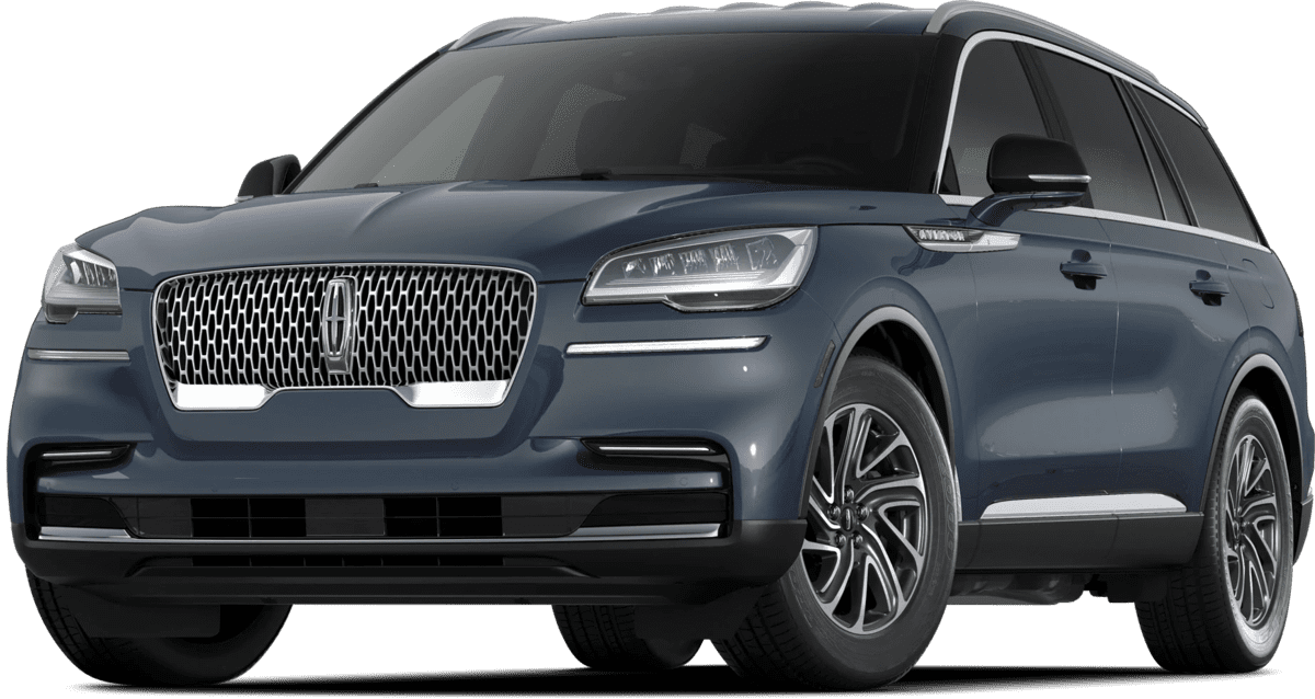
November 20, 2020 NHTSA CAMPAIGN NUMBER: 20V726000
The improperly manufactured knuckle may fracture, reducing steering control, increasing the risk of a crash.
NHTSA Campaign Number: 20V726
Manufacturer Ford Motor Company
Components STEERING
Potential Number of Units Affected 690
Summary
Ford Motor Company (Ford) is recalling certain 2021 Lincoln Aviator vehicles. The steering knuckles may have been manufactured improperly.
Remedy
Ford will notify owners, and dealers will inspect the front knuckle, and replace it if necessary, free of charge. The recall began December 16, 2020. Owners may contact Ford customer service at 1-866-436-7332. Ford’s number for this recall is 20S69.
Notes
Owners may also contact the National Highway Traffic Safety Administration Vehicle Safety Hotline at 1-888-327-4236 (TTY 1-800-424-9153), or go to www.safercar.gov.
Check if your Vehicle has a Recall
AFFECTED VEHICLES
| Vehicle | Model Year | Assembly Plant | Build Dates |
| Aviator | 2021 | Chicago | November 3, 2020 through November 13, 2020 |
REASON FOR THIS SAFETY RECALL
In some of the affected vehicles, an unacceptable void may have been created in the front wheel knuckle during the casting process. A knuckle with an unacceptable void may fracture while driving. Fracture of a front knuckle diminishes steering control, increasing the risk of a crash.
SERVICE ACTION
Before demonstrating or delivering any new in-stock vehicles involved in this recall, dealers are to inspect the manufacturing date code on both front wheel knuckles and replace the knuckle(s) that do not pass. This service must be performed on all affected vehicles at no charge to the vehicle owner.
OWNER NOTIFICATION AND MAILING SCHEDULE
Owner letters were mailed the week of December 7, 2020. Dealers should repair any affected vehicles that arrive at their dealerships, whether or not the customer has received a letter.
PARTS
| Part Number | Description | Order Quantity | Claim Quantity |
| -W720050-S440 | Tie Rod End Nut – 2 per side | As Required | |
| -W520216-S440 | Lower Arm to Knuckle Nut – 1 per side | As Required | |
| -W714660-S439 | Wheel Caliper to Knuckle Bolts – 2 per side | As Required | |
| -W719969-S900 | Front Wheel Bearing Bolts – 4 per side | As Required | |
| -W720123-S440 | Upper Ball Joint Nut – 1 per side | As Required | |
| LC5Z-3K186-A | Left Wheel Knuckle | As Required | |
| LC5Z-3K185-A | Right Wheel Knuckle | As Required | |
| LB5Z-3B477-A | Wheel Hub Nut AWD ONLY – 1 per side | As Required | |
SERVICE PROCEDURE
1. Turn the steering wheel to the full left position. Inspect and record the left hand wheel knuckle manufacturing date code. See Figure 1.
2. Turn the steering wheel to the full right position. Inspect and record the right hand wheel knuckle manufacturing date code.
3. Is the date code for the LH side knuckle 298?
Yes – Does not pass inspection, replace the wheel knuckle. Proceed to steps 4 and 5.
No – Passes inspection, replacement not required. Proceed to step 4.
4. Is the date code for the RH side knuckle 296 OR 297?
Yes – Does not pass inspection, replace the wheel knuckle. Proceed to step 5.
No – Passes inspection, replacement not required. This recall is complete.
5. Does the new replacement knuckle(s) have the suspect date code?
Yes – Does not pass inspection. Proceed to step 6.
No – Passes inspection, replace the wheel knuckle. Proceed to step 7.
6. Does the new replacement knuckle(s) have a white dot on it? See Figure 2.
Yes – Passes inspection, replace the wheel knuckle. Proceed to step 7.
No – Does not pass inspection. Contact SSSC for a new replacement knuckle.
7. Remove the front wheel bearing and wheel hub. Please follow the Workshop Manual (WSM) procedures in Section 204-01A for RWD vehicles and Section 204-01B for AWD vehicles.
8. Separate the outer tie-rod end from the wheel knuckle. See Figure 3.
1. Remove and discard the tie rod end nut.
Torque: 52 lb.ft (70 Nm)
2. Separate the tie rod end from the wheel knuckle.
Use the General Equipment: Tie Rod End Remover
NOTE: Do not use a hammer to separate the outer tie-rod end from the wheel knuckle or damage to the wheel knuckle may result.
NOTE: Use care when installing the tie rod separator or damage to the outer tie-rod end boot may occur.
9. Remove the brake hose bracket bolt and position aside the brake hose. See Figure 4.
Torque: 133 lb.in (15 Nm)
10. Remove and discard the front lower arm outboard nut. See Figure 5.
Torque: 76 lb.ft (103 Nm)
NOTE: Do not use power tools to remove or install the lower arm outboard nut. Damage to the ball joint or ball joint seal may occur.
NOTE: Use the TORX PLUS® holding feature to prevent the ball stud from turning while removing or installing the lower arm outboard nut. Torx® and TORX PLUS® is a reg. tm of Acument Intellectual Properties, LLC.
12. Remove and discard the rear lower arm outboard nut. See Figure 7.
Torque: 210 lb.ft (285 Nm)
NOTE: Do not use power tools to remove or install the lower arm outboard nut. Damage to the ball joint or ball joint seal may occur.
NOTE: Use the TORX PLUS® holding feature to prevent the ball stud from turning while removing or installing the lower arm outboard nut. Torx® and TORX PLUS® is a reg. tm of Acument Intellectual Properties, LLC.
11. Separate the front lower arm from the wheel Knuckle. See Figure 6.
Use Special Service Tool: 204-592 Separator, Lower Arm Ball Joint.
NOTE: Do not use a hammer, prying device, or separator fork to separate the ball joint from the wheel knuckle. Damage to the ball joint or ball joint seal may occur.
NOTE: Use care when releasing the lower arm and wheel knuckle into the resting position. Damage to the ball joint or ball joint seal may occur.
13. Separate the rear lower arm from the wheel Knuckle. See Figure 8.
Use Special Service Tool: 204-592 Separator, Lower Arm Ball Joint.
NOTE: Do not use a hammer, prying device, or separator fork to separate the lower arm from the ball joint. Damage to the ball joint or ball joint seal may occur.
NOTE: Use care when releasing the lower arm and wheel knuckle into the resting position. Damage to the ball joint or ball joint seal may occur.
14. Remove and discard the upper ball joint nut. See Figure 9.
Torque: 41 lb.ft (55 Nm)
NOTE: Do not use power tools to remove or install the lower arm outboard nut. Damage to the ball joint or
ball joint seal may occur.
NOTE: Use the TORX PLUS® holding feature to prevent the ball stud from turning while removing or installing the lower arm outboard nut. Torx® and TORX PLUS® is a reg. tm of Acument Intellectual Properties, LLC.
15. Separate the front upper arm from the wheel Knuckle. See Figure 10.
Use Special Service Tool: 204-592 Separator, Lower Arm Ball Joint.
NOTE: Do not use a hammer, prying device, or separator fork to separate the ball joint from the wheel knuckle. Damage to the ball joint or ball joint seal may occur.
NOTE: Use care when releasing the lower arm and wheel knuckle into the resting position. Damage to the ball joint or ball joint seal may occur.
16. Remove the wheel Knuckle. See Figure 11.
17. To install, reverse the removal procedure.
SEOCONTENT-START
December 2020
The Lincoln Motor Company
P. O. Box 1904
Dearborn, Michigan 48121 1904
* * * IMPORTANT SAFETY RECALL * * *
Safety Recall Notice 20S69 / NHTSA Recall 20V-726
2021 Aviator
Your Vehicle Identification Number (VIN):
This notice is sent to you in accordance with the National Traffic and Motor Vehicle Safety Act.
The Lincoln Motor Company has decided that a defect which relates to motor vehicle safety exists in
your vehicle, with the VIN shown above.
We apologize for this situation and want to assure you that, with your assistance, we will correct this
condition. Our commitment, together with your dealer, is to provide you with the highest level of service
and support.
What is the issue? On your vehicle, it may be possible that an unacceptable void may have
been created in the front wheel knuckle during the casting process.
What is the risk? A knuckle with an unacceptable void may fracture while driving. Fracture of
a front knuckle diminishes steering control, increasing the risk of a crash.
What will Lincoln and
your dealer do?
The Lincoln Motor Company has authorized your dealer to inspect the front
wheel knuckles and replace any knuckles that do not meet specifications
free of charge (parts and labor).
How long will it take? The time needed for this repair is less than one-half day. However, due to
service scheduling requirements, your dealer may need your vehicle for a
longer period of time. In addition, your vehicle will require an inspection to
determine if parts need to be ordered.
What should you do? Please call your dealer without delay to schedule a service appointment for
Recall 20S69. Provide the dealer with your VIN, which is printed near your
name at the beginning of this letter.
Lincoln has not issued instructions to stop driving your vehicle under this
safety recall. You should contact your dealer for an appointment to have
your vehicle remedied as soon as practicable. You can continue to safely
drive your vehicle.
Lincoln owners of 2017 Model Year or later vehicles affected by this recall
have the option of requesting complimentary Pickup & Delivery service with
a Lincoln vehicle for use during service. Please request Lincoln Pickup &
Delivery through your dealership if you would like to take advantage of this
option.
If you do not already have a servicing dealer, you can access
www.owner.Lincoln.com for dealer addresses, maps, and driving
instructions.
The Lincoln Motor Company wants you to have this safety recall completed
on your vehicle. The vehicle owner is responsible for making arrangements
to have the work completed.
Please note: Federal law requires that any vehicle lessor receiving this
recall notice must forward a copy of this notice to the lessee within ten
days.
JOHN A. SAMPLE
123 SAMPLE ST
SAMPLE CITY, MI 12345-6789
What should you do?
(continued)
NOTE: You can receive information about Recalls and Customer
Satisfaction Programs through The Lincoln Way App. The app can be
downloaded through the App Store or Google Play. In addition, there are
other features such as reserving and paying for parking in certain locations
and controlling certain functions on your vehicle (lock or unlock doors,
remote start) if it is equipped to allow control.
COVID-19
(CORONAVIRUS)
Lincoln dealerships have implemented enhanced protocols to ensure both
your safety and the safety of dealership employees. This includes specific
procedures for cleaning and disinfecting client vehicles and vehicles used
for Pickup & Delivery* both before and after each vehicle is serviced. In
most places, vehicle service has been deemed a critical service. Please
contact your local dealer to confirm current service hours. For more
information on how Lincoln and your local dealer are working hard to keep
you on the road during these challenging times, please visit
www.owner.Lincoln.com.
*Complimentary Lincoln Pickup & Delivery Service is available for all 2017
model year and newer Lincoln vehicles within the 4-year/50,000 mile New
Vehicle Limited Warranty. Contact your preferred dealer for important
details. Mileage limitations may apply.
Do you need a rental
vehicle?
If your dealer determines that knuckle replacement is required and needs
your vehicle overnight, your dealer is authorized to provide a rental vehicle
for your personal transportation at no charge (except for fuel and insurance)
while your vehicle is at the dealership for repairs. Please see your dealer for
guidelines and limitations.
What if you no longer
own this vehicle?
If you no longer own this vehicle, and have an address for the current
owner, please forward this letter to the new owner.
You received this notice because government regulations require that
notification be sent to the last known owner of record. Our records are
based primarily on state registration and title data, which indicate that you
are the current owner.
Can we assist you
further?
If you have difficulties getting your vehicle repaired promptly and without
charge, please contact your dealership’s Service Manager for assistance.
RETAIL OWNERS: If you have questions or concerns, please contact our
Customer Relationship Center at 1-866-436-7332 and one of our
representatives will be happy to assist you. If you wish to contact us through
the Internet, our address is: www.owner.Lincoln.com.
For the hearing impaired call 1-800-232-5952 (TDD). Representatives are
available Monday through Friday: 8:00AM – 8:00PM (Eastern Time).
FLEET OWNERS: If you have questions or concerns, please contact our
Fleet Customer Information Center at 1-800-34-FLEET, choose Option
#3, and one of our representatives will be happy to assist you. If you wish to
contact us through the Internet, our address is: www.fleet.Ford.com.
Representatives are available Monday through Friday: 8:00AM – 8:00PM
(Eastern Time).
If you are still having difficulty getting your vehicle repaired in a reasonable
time or without charge, you may write the Administrator, National Highway
Traffic Safety Administration, 1200 New Jersey Ave. S.E., Washington, D.C.
20590 or call the toll free Vehicle Safety Hotline at 1-888-327-4236
(TTY: 1-800-424-9153) or go to www.safercar.gov. Reference NHTSA
Safety Recall 20V-726.
Thank you for your attention to this important matter.
The Lincoln Motor Company
¿Qué debe hacer?
(continuación)
NOTA: puede recibir información sobre las campañas y los programas de
satisfacción del cliente a través de la aplicación Lincoln Way. La aplicación
se puede descargar a través de App Store o Google Play. Adicionalmente,
existen otras funciones como reserva y pago de estacionamientos en ciertos
lugares, además de control de ciertas funciones en el vehículo (bloqueo y
desbloqueo de puertas, arranque remoto) si así está equipado para permitir
el control.
COVID-19
(CORONAVIRUS)
Los distribuidores Lincoln han implementado protocolos mejorados con el fin
de asegurar tanto su seguridad como la de los empleados de los diferentes
distribuidores. Esto incluye procedimientos específicos de limpieza y
desinfección de los vehículos de los clientes y de los vehículos utilizados
para el servicio de retiro y entrega*, cada vez que se realiza algún servicio,
tanto antes como después de hacerlo. En la mayoría de los lugares, la
atención de vehículos se ha considerado un servicio esencial. Póngase en
contacto con su distribuidor local para confirmar las horas de servicio
actuales. Para obtener más información sobre cómo Lincoln y su distribuidor
local están trabajando arduamente para mantenerlo en las calles durante
estos tiempos difíciles, visite www.owner.Lincoln.com.
*El servicio complementario de retiro y entrega de Lincoln se encuentra
disponible para vehículos Lincoln año de modelo 2017 y posteriores, dentro
de la garantía limitada de vehículo nuevo de 4 años/50,000 millas. Para
obtener detalles importantes, póngase en contacto con el distribuidor de su
preferencia. Podrían aplicar límites de millaje.
¿Necesita un
vehículo de alquiler?
Si su distribuidor determina que es necesario efectuar el reemplazo del
mando y el vehículo debe permanecer en las instalaciones durante la noche,
el distribuidor está autorizado a ofrecerle un vehículo de alquiler para su
transporte personal sin costo (excepto el combustible y el seguro) mientras
su vehículo se encuentre en reparación. Comuníquese con su distribuidor
para conocer las pautas y limitaciones.
¿Qué pasa si usted
ya no es el
propietario del
vehículo?
Si usted ya no es el propietario del vehículo y tiene la dirección del
propietario actual, le solicitamos que le reenvíe esta carta.
Usted recibió este aviso porque las regulaciones del gobierno exigen el
envío de notificaciones al propietario conocido más reciente del registro.
Nuestros registros se basan principalmente en datos estatales y de
propiedad, que indican que usted es el propietario actual del vehículo.
¿Podemos hacer
algo más por usted?
Si tiene problemas para reparar de inmediato su vehículo y sin costo alguno,
comuníquese con el Gerente de Servicio de su distribuidor para solicitar
ayuda.
PROPIETARIOS MINORISTAS: si tiene dudas o preguntas, comuníquese
con nuestro Centro de Relación con Clientes al 1-866-436-7332 y uno de
nuestros representantes con gusto lo atenderá. Si desea comunicarse con
nosotros a través de Internet, nuestra dirección es: www.owner.Lincoln.com.
Las personas con problemas de audición pueden llamar al 1-800-232-5952
(TDD). Los representantes atienden de lunes a viernes, de 8:00 a.m. a
8:00 p.m. (hora del este).
PROPIETARIOS DE FLOTAS: si tiene dudas o preguntas, comuníquese con
nuestro Centro de Información a Clientes de flotas al 1-800-34-FLEET,
elija la opción n.° 3 y uno de nuestros representantes con gusto lo atenderá.
Si desea comunicarse con nosotros a través de Internet, nuestra dirección
es: www.fleet.Ford.com.
Los representantes atienden de lunes a viernes, de 8:00 a.m. a 8:00 p.m.
(hora del este).
Si continúa con dificultades para reparar su vehículo en un tiempo razonable
o sin cargo, le sugerimos que escriba al Administrador, National Highway
Traffic Safety Administration, 1200 New Jersey Ave. S.E., Washington, D.C.
20590 o bien que llame sin cargo a la línea directa de seguridad vehicular al
1-888-327-4236 (TTY: 1-800-424-9153) o visite www.safercar.gov.
Referencia: campaña de seguridad 20V-726 de la NHTSA.
Gracias por su atención en este asunto sumamente importante.
The Lincoln Motor Company
**************************************************************************************************************
Copyright 2020 Ford Motor Company
David J. Johnson Ford Motor Company
Director P. O. Box 1904
Service Engineering Operations Dearborn, Michigan 48121
Ford Customer Service Division
November 20, 2020
TO: All U.S. Ford and Lincoln Dealers
SUBJECT: NEW VEHICLE DEMONSTRATION / DELIVERY HOLD – Advance Notice –
Safety Recall 20S69
Certain 2021 Model Year Aviator Vehicles
Front Wheel Knuckle Inspection
AFFECTED VEHICLES
Vehicle Model Year Assembly Plant Build Dates
Aviator 2021 Chicago November 3, 2020 through November 13, 2020
Affected vehicles are identified in OASIS and FSA VIN Lists.
REASON FOR THIS SAFETY RECALL
In some of the affected vehicles, an unacceptable void may have been created in the front wheel
knuckle during the casting process. A knuckle with an unacceptable void may fracture while driving.
Fracture of a front knuckle diminishes steering control, increasing the risk of a crash.
SERVICE ACTION
DO NOT DEMONSTRATE OR DELIVER any new in-stock vehicles involved in this safety recall. A
complete Dealer Bulletin will be provided to dealers by the end of first quarter 2021 when it is
anticipated that parts ordering information and repair instructions will be available to support this
safety recall.
IMPORTANT: Dealers should open a Repair Order (RO) only when a full dealer bulletin is
published. Opening an RO against an Awareness or Advance Notice will result in warranty
rejections against a recall.
CUSTOMER NOTIFICATION
Owners of record will be notified via first-class mail that parts are not available to repair their vehicles.
RENTAL VEHICLES
To the extent a customer requests a rental vehicle until parts become available, Dealers are to
contact the Special Service Support Center (SSSC) for rental approval code.
PLEASE NOTE:
Federal law requires dealers to complete this recall service before a new vehicle is delivered to
the buyer or lessee. Violation of this requirement by a dealer could result in a civil penalty of
up to $21,000 per vehicle. Correct all vehicles in your new vehicle inventory prior to delivery.
Copyright 2020 Ford Motor Company
QUESTIONS & ASSISTANCE
For questions and assistance, contact the Special Service Support Center (SSSC) via the SSSC Web
Contact Site. The SSSC Web Contact Site can be accessed through the Professional Technician
Society (PTS) website using the SSSC link listed at the bottom of the OASIS VIN report screen or
listed under the SSSC tab.
Sincerely,
David J. Johnson
**************************************************************************************************************
Copyright 2021 Ford Motor Company
David J. Johnson Ford Motor Company
Director P. O. Box 1904
Service Engineering Operations Dearborn, Michigan 48121
Ford Customer Service Division
January 20, 2021
TO: All U.S. Ford and Lincoln Dealers
SUBJECT: NEW VEHICLE DEMONSTRATION / DELIVERY HOLD
Safety Recall 20S69 – Supplement #1
Certain 2021 Model Year Aviator Vehicles
Front Wheel Knuckle Inspection
REF: NEW VEHICLE DEMONSTRATION / DELIVERY HOLD
Safety Recall 20S69
Dated November 30, 2020
New! REASON FOR THIS SUPPLEMENT
Parts Requirements / Ordering Information: All parts are now available to order normally.
Parts Requirements / Ordering Information: Added the complete parts list.
Attachment III: Added two new steps to inspect the date code on the new wheel knuckle(s)
and verify that they have passed testing by the presence of a white dot.
PLEASE NOTE:
Federal law requires dealers to complete this recall service before a new vehicle is delivered to
the buyer or lessee. Violation of this requirement by a dealer could result in a civil penalty of
up to $21,000 per vehicle. Correct all vehicles in your new vehicle inventory before delivery.
Copyright 2021 Ford Motor Company
New! ATTACHMENTS
Attachment I: Administrative Information
Attachment II: Labor Allowances and Parts Ordering Information
Attachment III: Technical Information
Owner Notification Letters
QUESTIONS & ASSISTANCE
For questions and assistance, contact the Special Service Support Center (SSSC) via the SSSC Web
Contact Site. The SSSC Web Contact Site can be accessed through the Professional Technician
Society (PTS) website using the SSSC link listed at the bottom of the OASIS VIN report screen or
listed under the SSSC tab.
Sincerely,
David J. Johnson
Copyright 2021 Ford Motor Company
ATTACHMENT I
Page 1 of 2
NEW VEHICLE DEMONSTRATION / DELIVERY HOLD
Safety Recall 20S69 – Supplement #1
Certain 2021 Model Year Aviator Vehicles
Front Wheel Knuckle Inspection
OASIS ACTIVATION
OASIS was activated on November 20, 2020
FSA VIN LISTS ACTIVATION
FSA VIN Lists have been available through https://web.fsavinlists.dealerconnection.com since
November 20, 2020. Owner names and addresses have been available since January 4, 2021.
NOTE: Your FSA VIN Lists may contain owner names and addresses obtained from motor vehicle
registration records. The use of such motor vehicle registration data for any purpose other than in
connection with this recall is a violation of law in several states, provinces, and countries. Accordingly,
you must limit the use of this listing to the follow-up necessary to complete this recall.
SOLD VEHICLES
Ford has not issued instructions to stop selling/delivering or driving used vehicles under this
safety recall. Owners should contact their dealer for an appointment to have their vehicles
remedied as soon as practicable. Owners can continue to safely drive their vehicles.
Immediately contact any of your affected customers whose vehicles are not on your VIN list
but are identified in OASIS. Give the customer a copy of the Owner Notification Letter (when
available) and schedule a service date.
Correct other affected vehicles identified in OASIS which are brought to your dealership.
Dealers are to prioritize repairs of customer vehicles over repairs of new and used vehicle
inventory.
STOCK VEHICLES
Correct all affected units in your new vehicle inventory before delivery.
Use OASIS to identify any affected vehicles in your used vehicle inventory.
DEALER-OPERATED RENTAL VEHICLES
The Fixing America’s Surface Transportation (FAST) Act law effective June 2016 prohibits a rental
company from selling, renting or leasing vehicles subject to a safety or compliance recall. Please
consult your legal counsel for legal advice.
TITLE BRANDED / SALVAGED VEHICLES
Affected title branded and salvaged vehicles are eligible for this recall.
OWNER REFUNDS
Refunds are not approved for this program.
RENTAL VEHICLES
Dealers are pre-approved for up to 1 day for a comparable rental vehicle. Follow Extended Service
Plan (ESP) guidelines for dollar amounts. Rentals will only be reimbursed for the day(s) the vehicle is
at the dealership for part replacement. Prior approval for more than 1 rental day(s) is required from
the SSSC. Contact the SSSC via the SSSC Web Contact Site for consideration and approval if
appropriate.
Copyright 2021 Ford Motor Company
ATTACHMENT I
Page 2 of 2
NEW VEHICLE DEMONSTRATION / DELIVERY HOLD
Safety Recall 20S69 – Supplement #1
Certain 2021 Model Year Aviator Vehicles
Front Wheel Knuckle Inspection
LINCOLN PICKUP AND DELIVERY
Owners of 2017 MY and newer Lincoln vehicles have the option of requesting pickup and delivery
service with a Lincoln loaner (up to 2 days), from their dealership. For details, reference EFC08708,
2021 Lincoln Pickup & Delivery Updates. Claim the difference of pre-approved days, or any additional
rental days approved by the SSSC as instructed.
ADDITIONAL REPAIR (LABOR TIME AND/OR PARTS)
Additional repairs identified as necessary to complete the FSA should be managed as follows:
For related damage and access time requirements, refer to the Warranty and Policy Manual /
Section 6 – Ford & Lincoln Program Policies / General Information & Special Circumstances
for FSA’s / Related Damage.
For vehicles within new vehicle bumper-to-bumper warranty coverage, no SSSC approval is
required, although related damage must be on a separate repair line with the “Related
Damage” radio button checked.
o Lincoln vehicles – 4 years or 50,000 miles
For vehicles outside new vehicle bumper-to-bumper warranty coverage, submit an Approval
Request to the SSSC Web Contact Site prior to completing the repair.
CLAIMS PREPARATION AND SUBMISSION
Claim Entry: Enter claims using Dealer Management System (DMS) or One Warranty
Solution (OWS) online.
o When entering claims, select claim type 31: Field Service Action. The FSA number
20S69 is the sub code.
o For additional claims preparation and submission information, refer to the Recall and
Customer Satisfaction Program (CSP) Repairs in the OWS User Guide.
Related Damage/Additional labor and/or parts: Must be claimed as Related Damage on a
separate repair line from the FSA with same claim type and sub code as described in Claim
Entry above.
IMPORTANT: Click the Related Damage Indicator radio button.
Rentals: For rental vehicle claiming, follow Extended Service Plan (ESP) guidelines for dollar
amounts. Enter the total amount of the rental expense under Miscellaneous Expense code
RENTAL.
Copyright 2021 Ford Motor Company
ATTACHMENT II
Page 1 of 2
NEW VEHICLE DEMONSTRATION / DELIVERY HOLD
Safety Recall 20S69 – Supplement #1
Certain 2021 Model Year Aviator Vehicles
Front Wheel Knuckle Inspection
LABOR ALLOWANCES
Description Labor Operation Labor Time
Inspect both wheel knuckle date codes. – Both Pass 20S69A 0.3 Hours
Inspect both wheel knuckle date codes and replace one (1)
wheel knuckle – AWD 20S69B 1.5 Hours
Inspect both wheel knuckle date codes and replace two (2)
wheel knuckle – AWD 20S69C 2.6 Hours
Inspect both wheel knuckle date codes and replace one (1)
wheel knuckle – RWD 20S69D 1.2 Hours
Inspect both wheel knuckle date codes and replace two (2)
wheel knuckle – RWD 20S69E 2.1 Hours
New! PARTS REQUIREMENTS / ORDERING INFORMATION
Part Number Description Order
Quantity
Claim
Quantity
-W720050-S440 Tie Rod End Nut – 2 per side As Required
-W520216-S440 Lower Arm to Knuckle Nut – 1 per side As Required
-W714660-S439 Wheel Caliper to Knuckle Bolts – 2 per side As Required
-W719969-S900 Front Wheel Bearing Bolts – 4 per side As Required
-W720123-S440 Upper Ball Joint Nut – 1 per side As Required
LC5Z-3K186-A Left Wheel Knuckle As Required
LC5Z-3K185-A Right Wheel Knuckle As Required
LB5Z-3B477-A Wheel Hub Nut AWD ONLY – 1 per side As Required
Note: There are several wheel knuckles in the parts distribution system with a suspect date code.
Parts with the suspect date code AND a white paint dot near the date code are approved for
installation. See Part Inspection procedure in the Service Instructions.
Order your parts through normal order processing channels. To guarantee the shortest delivery time,
an emergency order for parts must be placed.
DEALER PRICE
For latest prices, refer to DOES II.
Copyright 2021 Ford Motor Company
ATTACHMENT II
Page 2 of 2
NEW VEHICLE DEMONSTRATION / DELIVERY HOLD
Safety Recall 20S69 – Supplement #1
Certain 2021 Model Year Aviator Vehicles
Front Wheel Knuckle Inspection
PARTS RETENTION, RETURN, & SCRAPPING
Follow the provisions of the Warranty and Policy Manual, Section 1 – WARRANTY PARTS
RETENTION AND RETURN POLICIES. If a replaced part receives a scrap disposition, the part must
be scrapped in accordance with all applicable local, state and federal environmental protection and
hazardous material regulations. Federal law prohibits selling motor vehicle parts or components that
are under safety, compliance, or emissions recall.
EXCESS STOCK RETURN
Excess stock returned for credit must have been purchased from Ford Customer Service Division in
accordance with Policy Procedure Bulletin 4000.
ATTACHMENT III
PAGE 1 OF 6
SAFETY RECALL 20S69-S1
CPR © 2021 FORD MOTOR COMPANY
DEARBORN, MICHIGAN 48121
1/2021
CERTAIN 2021 MODEL YEAR AVIATOR VEHICLES — FRONT KNUCKLE
INSPECTION
**************************************************************************************************************
**************************************************************************************************************
SEOCONTENT-END
1 Affected Product
Vehicle
| MAKE | MODEL | YEAR |
| LINCOLN | AVIATOR | 2021 |
10 Associated Documents
Owner Notification Letter(Part 577)
RCONL-20V726-9297.pdf 346.513KB
Manufacturer Notices(to Dealers,etc) – Dealer Notification re NEW VEHICLE DEMONSTRATION / DELIVERY HOLD Safety Recall 20S69 Certain 2021 Model Year Aviator Vehicles Front Wheel Knuckle Inspection
RCMN-20V726-8396.pdf 2476.409KB
Manufacturer Notices(to Dealers,etc) – Dealer Notification re NEW VEHICLE DEMONSTRATION / DELIVERY HOLD Safety Recall 20S69 – Supplement #1 Certain 2021 Model Year Aviator Vehicles Front Wheel Knuckle Inspection
Recall Quarterly Report #3, 2021-2
RCLQRT-20V726-2004.PDF 211.309KB
Defect Notice 573 Report
RCLRPT-20V726-2998.PDF 214.295KB
Manufacturer Notices(to Dealers,etc) – Dealer Notification re NEW VEHICLE DEMONSTRATION / DELIVERY HOLD – Advance Notice – Safety Recall 20S69 Certain 2021 Model Year Aviator Vehicles Front Wheel Knuckle Inspection
RCMN-20V726-5863.pdf 144.625KB
Recall Quarterly Report #2, 2021-1
RCLQRT-20V726-6985.PDF 211.218KB
Recall Quarterly Report #1, 2020-4
RCLQRT-20V726-2929.PDF 211.121KB
Recall Acknowledgement
RCAK-20V726-5938.pdf 244.147KB
Recall Quarterly Report #4, 2021-3
RCLQRT-20V726-2394.PDF 211.414KB
Latest Recalls Documents

- ESSENTIAL TOOL FOR BALL JOINT SERVICE - Use the ORION MOTOR TECH Ball Joint Press Set Ball Joint Tool / Bushing Removal Tool with 4WD Adapter to effortlessly remove press fit parts including ball joints, U-joints, brake anchor pins, and more on most 2-wheel drive (2WD) and 4-wheel drive (4WD) vehicles without removing the control arm from the vehicle.
- PROFESSIONAL GRADE QUALITY AND DURABILITY - Off road weekend warriors, novices, and professional mechanics trust the ORION kit because ORION MOTOR TECH sources the highest quality components from around the world. Constructed from heavy-duty forged steel with black-oxide finish on adapters for maximum strength and longevity that resists rust and corrosion.
- UNIVERSALLY COMPATIBLE WITH A WIDE RANGE OF VEHICLES - Fit most American domestic and imported 2-wheel drive (2WD) and 4-wheel drive (4WD) cars and light pickup trucks that have press-fit type ball joints, include 4-wheel drive (4WD) adapter that allows service for 1967 thru current 1/2 and 3/4 ton 4WD vehicles having the Dana 30 or 44 front axle (found on Ford, GM, Dodge, IHC and Jeep vehicles).
- CONVENIENTLY ORGANIZED IN CUSTOM MOLDED CASE - Ball joint press / bushing/ removal tool kit is enclosed inside a heavy-duty 11” x 3” x 15” inch (27.9cm x 7.6cm x 38.1cm) plastic blow-molded carrying case with handle for easy storage, safe storage, and quick organization. Package include: 3x Receiving Tube, 1x Removal Adapter, 1x Installation Adapter, 1x Screw, 1x Install Cup Adapter, 1x Forcing-screw Press, 1x Receiving Cup, 1x Installing Cup.
- ORION MOTOR TECH - We pursue outstanding quality and professional technical support. If you are not satisfied with this product or if you have any question, please feel free to let us know.
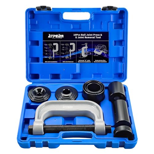
- Premium Quality: This ball joint tool kit is made of solid carbon steel with anti-rust finish, perfect for removal/installation of press-fit parts, such as ball joints, universal joint and truck brake anchor pins.
- Easy To Use: It will help you effortlessly remove press fit parts including ball joints, U-joints, brake anchor pins without removing the control arm from the vehicle. Besides, this tool kit can also remove rusted and corroded parts. Really save your energy and time in daily life.
- Package Included: 3x Receiving Tubes, 1x Removal Adapter, 1x Installation Adapter, 1x Screw, 1x Install Cup Adapter, 1x Forcing-screw Press, 1x Receiving Cup, 1x Installing Cup.
- Wide Application: The heavy duty 4-wheel drive ball joint tool is compatible with most American domestic and imported 2-wheel drive (2WD) and 4-wheel drive (4WD) cars. It allows service for 1/2 and 3/4 ton 4WD vehicles
- Blow Storage Case: The Ball Joint Press set is packed in a heavy-duty, storage case with precision-sized compartments for every piece - great for storage and transport while lengthening the life of the tool set.

- Complete Tool Set: Orion Motor Tech's master ball joint removal tool kit includes a 5 pc. front-end service tool kit and a 21 pc. ball joint tool set. It provides everything you need for removing and installing ball joints, tie rods, Pitman arms, & more
- Wide Compatibility: This ball joint servicing kit is compatible with most GM, Chevrolet, Ford, and Dodge vehicles with 2WD or 4WD setups, including Dana 28, 30, 35, 44, & 60 axles. It works on light trucks, vans, SUVs, & many domestic & imported vehicles
- Easy Operation: Our 21-piece ball joint press kit lets you service joints and anchor pins without removing control arms. The multiple adapter sizes speed up ball joint and U-joint removal on most vehicles
- Rugged Build: Built from high-strength forged steel, this suspension service kit handles the toughest jobs. With a protective black oxide coating, these ball joint tools withstand corrosion and are built for long-term garage or shop use
- Carry Case Included: The convenient ABS storage case is built to store each ball joint press tool in a custom-molded slot. Stay organized during every job and avoid delays from misplaced tools or missing parts

- EASY OPERATION: Use the ORION MOTOR TECH Ball Joint Press Tool Set with 4WD Adapter to effortlessly remove press-fit parts including ball joints, U-joints, brake anchor pins, and more on most 2-wheel drive (2WD) and 4-wheel drive (4WD) vehicles without removing the control arm.
- UNIVERSAL COMPATIBILITY: Fits most American domestic and imported cars and light pickup trucks with press-fit type ball joints. Includes a 4WD adapter for service on 1967 - current 1/2 and 3/4 ton 4WD vehicles with the Dana 30 or 44 front axle (found on Ford, GM, Dodge, IHC, and Jeep vehicles).
- PROFESSIONAL-GRADE DURABILITY: Constructed from heavy-duty forged steel with black-oxide finished adapters for maximum strength and longevity that resists rust and corrosion to endure years of heavy use.
- ALL-IN-ONE TOOL KIT: 3x Receiving Tubes, 1x Removal Adapter, 1x Installation Adapter, 1x Screw, 1x Install Cup Adapter, 1x Forcing-screw Press, 1x Receiving Cup, 1x Installing Cup.
- PROTECTIVE CARRYING CASE: Each component is contained in a heavy-duty plastic carrying case with a handle for safe storage and quick organization.

- Gearwrench's Ball Joint Separator is made for separating the ball joint from the spindle support arm on domestic and import front wheel drive vehicles
- Adjustable for different size ball joints
- Suitable for most cars and light trucks (not intended for use on 3/4 ton or 1 ton trucks)
- Works on ball joints from 1-1/8” to 2-1/8” and 30 to 56mm in size
- Slot is 7/8" wide by 1-1/4" Deep

This product presentation was made with AAWP plugin.