| “This site contains affiliate links for which OEMDTC may be compensated” |
| TSB 17-0006 | AUXILIARY JUNCTION BOX – INOPERATIVE AUXILIARY RELAY AND/OR INOPERATIVE UPFIT SWITCH 3 – BUILT ON OR BEFORE 17-OCT-2016 |
| Publication Date: January 18, 2017 | |
FORD : : | 2017 Transit |
ISSUE:
Some 2017 Transit vehicles equipped with an auxiliary junction box and built on or before 17-Oct-2016 may exhibit an inoperative auxiliary relay 8 and/or an inoperative upfit switch 3. This may be due to a missing relay ground circuit.
ACTION:
Follow the Service Procedure steps to correct the condition.
SERVICE PROCEDURE
- Disconnect the battery ground cable(s). Refer to Workshop Manual, Section 414-01.
- Release the clips and remove the right side mounted cupholder.
- Open the glove box and press the stop tabs downward and fully lower the glove compartment door.
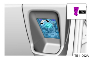
- Release the 2 clips and remove the right side access panel. This allows access to right side instrument panel finish panel screws. (Figure 1)

Figure 1 – 17-0006 - Remove the 5 screws, release the 5 clips and remove the right side instrument panel finish panel.
- Locate auxiliary fuse panel 2 through the glove box opening and remove it from the bracket by pressing the latch feature.
- Remove the top and bottom auxiliary fuse panel covers. Remove the fuses and relays.
- Remove the terminal locking wedge by gently pressing on the catch feature using a small flat head screwdriver.
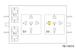
- Install the female terminal of the new jumper circuit into the location for auxiliary relay 8 pin 2. (Figure 2)

Figure 2 – 17-0006 - Reinstall the locking wedge, both relays, both fuses, top and bottom panel covers.
- Route the new jumper circuit along the harness to ground G306. Secure the jumper to the harness with cable tie straps.
- Locate and remove the ground screw for the single eyelet ground G306. Do not remove the screw for the ground with double interlocking eyelets.
- Attach both the new jumper circuit and original ground G306 eyelets with the ground screw at the original location.
- Tighten screw to 12 Nm (8.8 lb-ft)
- Secure the fuse box by sliding it onto its bracket.
- Install the right side instrument panel finish panel.
- Tighten screws to 2 Nm (18 lb-in)
- Install the right side access panel. (Figure 1)
- Press the glove box stop tabs and close the glove compartment.
- Install the right side mounted cupholder.
- Reconnect the battery ground cable(s). Refer to Workshop Manual, Section 414-01.
| HK4Z-14A411-CA | Jumper |
| OPERATION | DESCRIPTION | TIME |
| 170006A | 2017 Transit: Install Jumper Wire To Auxiliary Junction Box (Do Not Use With Any Other Labor Operations) | 0.7 Hr. |
WARRANTY STATUS
Eligible Under Provisions Of New Vehicle Limited Warranty Coverage.
Warranty/ESP coverage limits/policies/prior approvals are not altered by a TSB. Warranty/ESP coverage limits are determined by the identified causal part and verified using the OASIS part coverage tool.
DEALER CODING
| BASIC PART NO. | CONDITION CODE |
| 14401 | 28 |
 Loading...
Price Disclaimer


![Inoperative Auxiliary Relay 8 and/or an Inoperative Upfit Switch 3 - 2017 Ford Transit 10 True MODS 1 Pack 5-Pin 12V Bosch Style Waterproof Relay Kit [Harness Socket] [12 AWG Hot Wires] [SPDT] [30/40 Amp] 12 Volt Automotive Marine Relays for Boats Auto Fan Cars](https://m.media-amazon.com/images/I/41kuW9VnZxL._SL75_.jpg)
