| “This site contains affiliate links for which OEMDTC may be compensated” |
| 6.8L – STATIONARY SECONDARY ELEVATED IDLE CONTROL (SEIC) POWER TAKE OFF (PTO) INOPERATIVE – BUILT ON OR BEFORE 10/22/2015 |
FORD : : | 2016 F-650, F-750 |
ISSUE:
Some 2016 F-Super Duty 650/750 vehicles equipped with a 6.8L engine may exhibit an inoperative PTO due to wiring circuit CE326 being installed in the incorrect powertrain control module (PCM) connector cavity of C175B.
ACTION:
Follow the Service Procedure steps to correct the condition.
SERVICE PROCEDURE
- Check the vehicle build date. Was the vehicle built on or before 10/22/2015?
- Yes – proceed to Step 2.
- No – this article does not apply. Refer to Powertrain Control/Emissions Diagnosis (PC/ED) manual for PTO Controls Diagnostics or the Truck Body Builders Advisory Service website, the Body Builders Layout Book or the Special Vehicle Engineering Quality Bulletin Index for the latest information on Stationary SEIC operation.
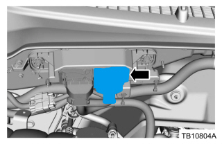
- Locate PCM connector C175B. Refer to Wiring Diagram, Electronic Engine Controls. Disconnect C175B from the PCM. Refer to WSM, Section 303-14. (Figure 1)
Figure 1
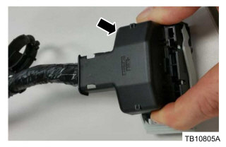
- Cut the tie strap securing the wire dress cover to the bundle and remove the wire dress cover. (Figure 2)
Figure 2
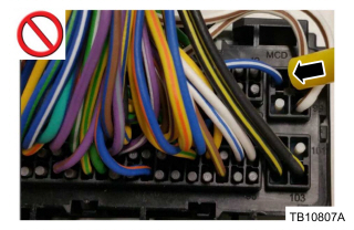
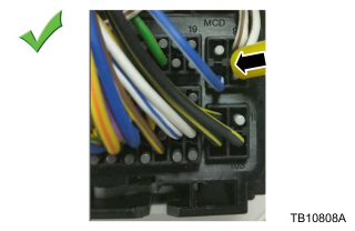
- Is circuit CE326 (BU-WH) located in connector C175B cavity 96? (Figure 3)
- Yes – proceed to Step 5.
- No – this article does not apply. Refer to PC/ED manual for normal diagnosis.
Figure 3
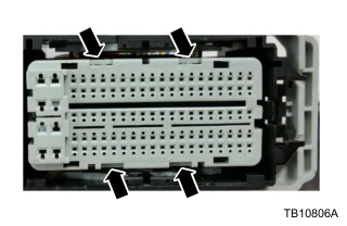
Figure 4
- Using wire terminal release tool NUD 900-001 or equivalent, remove the plug from cavity 98.
- Remove circuit CE326 (BU/WH) from cavity 96 and insert it in cavity 98 using the wire terminal release tool. (Figure 5)
- Install the plug removed from cavity 98 into cavity 96.
Figure 5
- Reinstall the grey terminal lock insert in the front of the connector until fully seated.
- Reinstall the wire dress cover and secure it to the bundle using a tie strap.
- Connect C175B to the PCM. Refer to WSM Section, 303-14.
| Obtain Locally | |
| Part Description | |
| Tie Strap |
Price Disclaimer
