| TSB 15-0119 | POOR AUDIO SYSTEM RECEPTION OR WHISTLING-TYPE NOISE ON AM OR AM-HD BANDS ONLY – BUILT ON OR BEFORE 11/30/2013 |
| FORD: | 2013-2014 Flex |
This article supersedes TSB 14-0051 to update the Service Procedure, Parts List and Service Labor Time Standards.
ISSUE:
Some 2013-2014 Flex vehicles built on or before 11/30/2013 may exhibit a concern of poor audio system reception or a whistling-type noise on AM or AM-HD bands only.
ACTION:
Follow the Service Procedure steps to correct the condition.
SERVICE PROCEDURE
- Does the audio system exhibit reception concerns or abnormal noises on FM band and/or satellite radio channels?
- Yes – this procedure does not apply. Refer to Workshop Manual (WSM), Section 415-00 for normal diagnosis.
- No – proceed to Step 2.
- Is the vehicle built on or after 3/02/2013?
- Yes – proceed to Step 5.
- No – remove the antenna base. Refer to WSM, Section 415-00.
- Inspect the antenna base part number located on the underside of the part.
- Is the part number either DA8T-19G461-AC or DA8T-19G461-AD? (Figure 1)
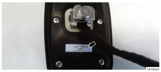
Figure 1 – 15-0119 - Replace both the front and rear antenna cables. Refer to WSM, Section 415-00.
- Cut circuit VME43 approximately 5 cm (2″) from the male side of connector C212.
- On the replacement rear antenna cable kit, cut the exposed pin off the blue power wire.
- Splice the rear antenna cable blue power wire, from the replacement antenna cable kit, to the 5 cm (2″) portion of circuit VME43, on connector C212. Use wire kit and recommended solder splicing method located in Wiring Diagram, Section 5.
| DA8Z-18936-B | Antenna Base |
| DA8Z-18812-A | Front Antenna Cable – AM/FM Only |
| DA8Z-18812-B | Rear Antenna Cable |
| DA8Z-18812-C | Front Antenna Cable – AM/FM/SAT |
| CU5Z-14A411-A | Wire Splice Kit |
| OPERATION | DESCRIPTION | TIME |
| 150119A | 2013-2014 Flex: Remove The Antenna Base, Replace If Necessary And Replace Both Antenna Cables Includes Time To Splice Wire (Do Not Use With Any Other Labor Operations) | 2.9 Hrs. |
WARRANTY STATUS
Eligible Under Provisions Of New Vehicle Limited Warranty Coverage.
Warranty/ESP coverage limits/policies/prior approvals are not altered by a TSB. Warranty/ESP coverage limits are determined by the identified causal part and verified using the OASIS part coverage tool.
DEALER CODING
| BASIC PART NO. | CONDITION CODE |
| 18936 | 01 |

BOSS Audio Systems R1100M 1100 Watt Monoblock Car Amplifier
- DIMENSIONS: 10.43" x 9.21" x 2.25", WEIGHT: 4.37 lbs
- SPECS: Monoblock, Class A/B, 2Ω Stable, MOSFET Power Supply, 1100 Max x 1 @ 2 Ohms, 550 Max x 1 @ 4 Ohms
- SPECS CONT'D: Low Pass Filter, Bass Boost, Input Sensitivity, Illuminated Logo, Thermal, Short and Overload Protection Circuits, Remote Subwoofer Control
- INPUTS/OUTPUTS: RCA & Speaker Level Inputs
- WARRANTY: BOSS Audio Systems provides a powerful 6-year platinum online dealer warranty so long as the purchase is made through Amazon.com. We strongly encourage professional installation of this product to ensure proper and safe functionality
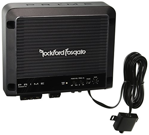
Rockford Fosgate R500X1D Prime 1-Channel Class D Amplifier
- 23% Increase of Thermal Mass Per Square Inch
- Small Chassis Design
- OEM Vehicle Integration
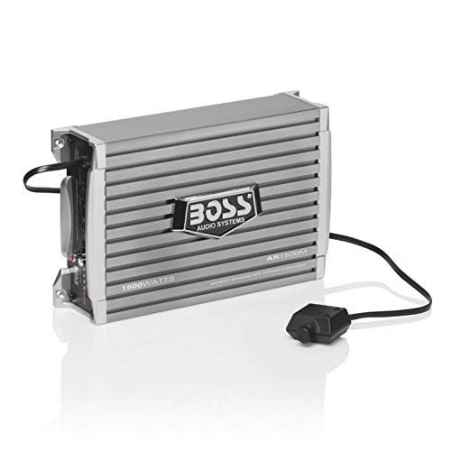
BOSS Audio Systems AR1500M Monoblock Car Amplifier - 1500 High Output, High/Low Level Inputs, Low Pass Crossover, Hook Up to Subwoofer for Bass
- POWER: Maximum Power Output of 1500 Watts at 2 Ohms into one channel. MAX Power Output of 750 Watts at 4 Ohms into one Channel. This amplifier is designed to run your subwoofer(s) giving them the power that they need to perform as they were meant to
- HIGH LEVEL INPUTS: Speaker level inputs are commonly referred to as high-level inputs. Speaker level inputs will be used to connect the AR1500M to your factory radio or an aftermarket radio that does not have low-level (RCA) inputs
- LOW LEVEL INPUTS: Line level inputs, also known as RCA inputs or low-level inputs, use RCA interconnect cables to link the AR1500M with the source unit. Most aftermarket radios have multiple pairs of RCA outputs that can connect to multiple amplifiers
- LOW-PASS CROSSOVER: A low-pass filter is an electronic circuit that removes all the notes below the filter's frequency setting. You will use the Low-pass filter to primarily keep high notes out of your subwoofer(s)
- SWITCHABLE BASS BOOST: Switchable Bass Boost allows you to boost the low bass +18db.
This product presentation was made with AAWP plugin.